I. Project Requirements:
There was a need to observe the color changes of RGB LEDs using an oscilloscope.
A quick online search revealed that the cheapest options were mostly I2C modules.
Thinking about it, since I already had an oscilloscope, why not read the data through waveforms?
Further searching for sensors revealed almost none with analog output.
In principle, it involves a photoresistor with different filters. I remembered that LEDs also generate electricity, and the voltage is proportional to the brightness. So, do different colored LEDs have different colored filters?
The principle seemed feasible, so I started testing.
II. LED Testing:
Using a WS2812 tuned to white light, the voltage of different colored LEDs under direct illumination was measured, and the results are shown in the table below.
Color Sensor |
Red LED |
Emerald Green LED
| Blue LED
| Yellow LED |
Red (FF0000) |
1150mV
| 3mV
|
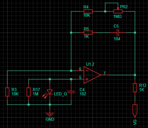
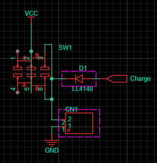
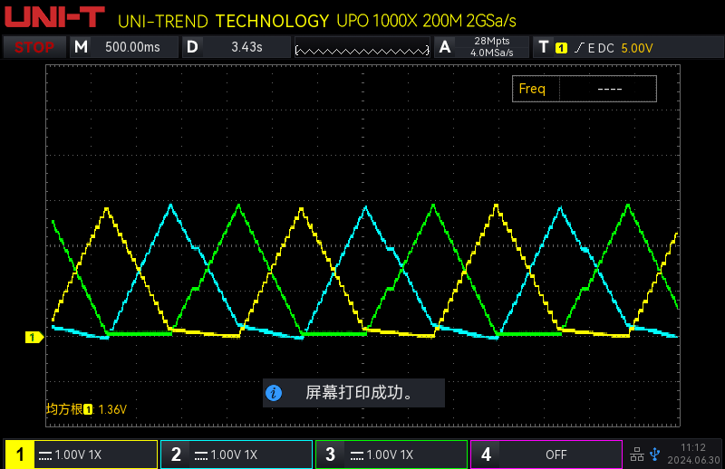
0mV | 7mV | Green ( 00FF00) | 103mV | 216mV | 0mV | 1364mV | Blue (0000FF) | 15mV | 980mV | 431mV | 172mV | Yellow (FFFF00) | 1130mV | 206mV | 0mV | 1376mV | Cyan (00FFFF) | 120mV | 1024mV | 431mV | 1397mV | Violet (FF00FF) | 1100mV | 824mV | 431mV | 183mV | White (FFFFFF) | 1100mV | 983mV The conclusions are as follows: 426mV 1402mV. The light filtering effect of some LEDs is unsatisfactory. For example, the green LED's filtering of the green wavelength of the WS2812 is not as good as that of the yellow LED . The peak voltage is inconsistent, requiring different gains for each channel . Sunlight wavelengths are more diverse, and the voltage is higher than shown in the table. Because the sun's wavelength is not constant, it is not listed separately. III. Circuit Principle : The circuit is relatively simple, consisting of an adjustable gain non-inverting amplifier circuit with different low-pass filters added to remove power frequency interference. The parameters were determined after testing. The power supply uses a lithium battery. Since I also have an adjustable power supply and a multimeter on my desk, the lithium battery charging circuit and voltage measurement circuit are omitted. This circuit is specifically designed for measuring RGB on the test bench. IV. Functional Demonstration: This is the waveform of my keyboard's RGB lighting effects. The linearity is good. The stepped effect is due to my algorithm. Channels 1-3 correspond to RGB. It can be seen that the red channel is slightly affected by green, and the green channel is affected by blue. The blue channel is the best. This matches the measurement results above. Don't be fooled by the oscilloscope's specifications. This oscilloscope is playing word games. It has two dual-channel ADCs, and the sampling rate refers to the sum of the sampling rates of the two ADCs, which I can accept. However, its bandwidth is also the sum of two 100M bandwidths.


 京公网安备 11010802033920号

 BUS-61569-540L


