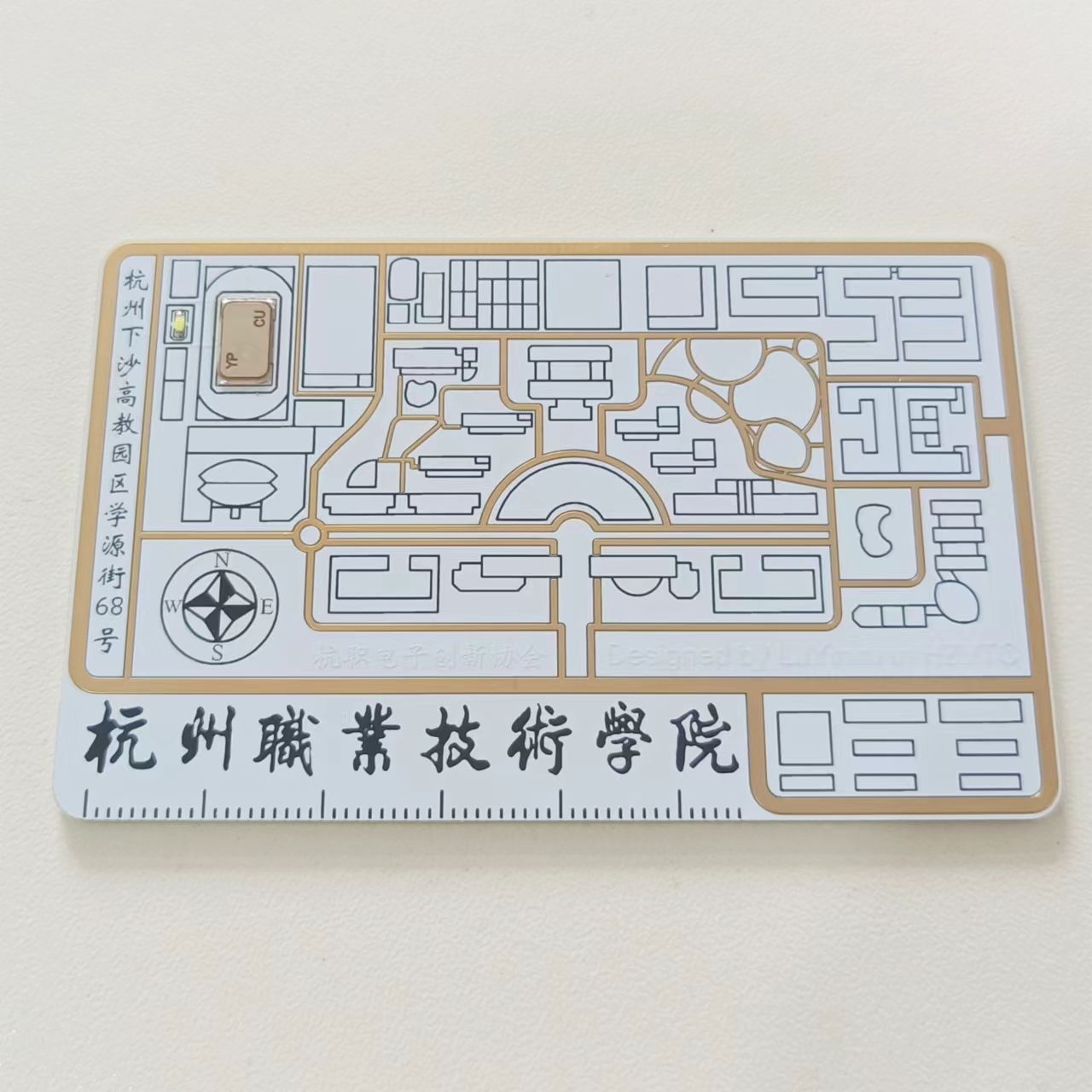
The Hangzhou Vocational and Technical College themed NFC card
features a white immersion gold finish, which looks very attractive in hand.
For aesthetic reasons, no QR code or custom code is included; this version is recommended without a custom code.
The NFC chip is only compatible with *58mm** COB packaged NFC chips.
Please choose the appropriate chip type (UID, CUID, UFID, etc.) according to your needs. I purchased a more universal CUID chip, which can be bought on Taobao.
Taobao sellers generally offer NFC chips with and without solder; both can be soldered, but the non-soldered version is recommended.
The LED is a 0603 specification (soldering direction and color are arbitrary).
Soldering Precautions:
Since the LED is close to the adjacent pads, please be careful to avoid getting solder on them.
Because the NFC chip solder joints face downwards, it is recommended to use a hot air gun or heating plate for soldering. Soldering with a soldering iron is also possible, but requires a certain level of skill and experience.
When using solder paste, apply a slightly larger amount to ensure full coverage of the solder joints when the hot air gun is used.
Front view:
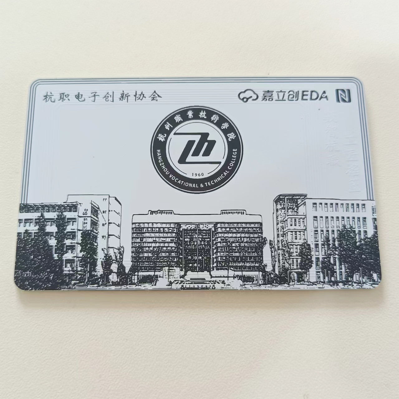
Back view:
LED lighting effect during use:

PDF_Hangzhou Vocational College Themed NFC Card.zip
Altium_Hangzhou Vocational College Themed NFC Card.zip
PADS_Hangzhou Vocational and Technical College Themed NFC Card.zip
BOM_Hangzhou Vocational and Technical College Themed NFC Card.xlsx
95080
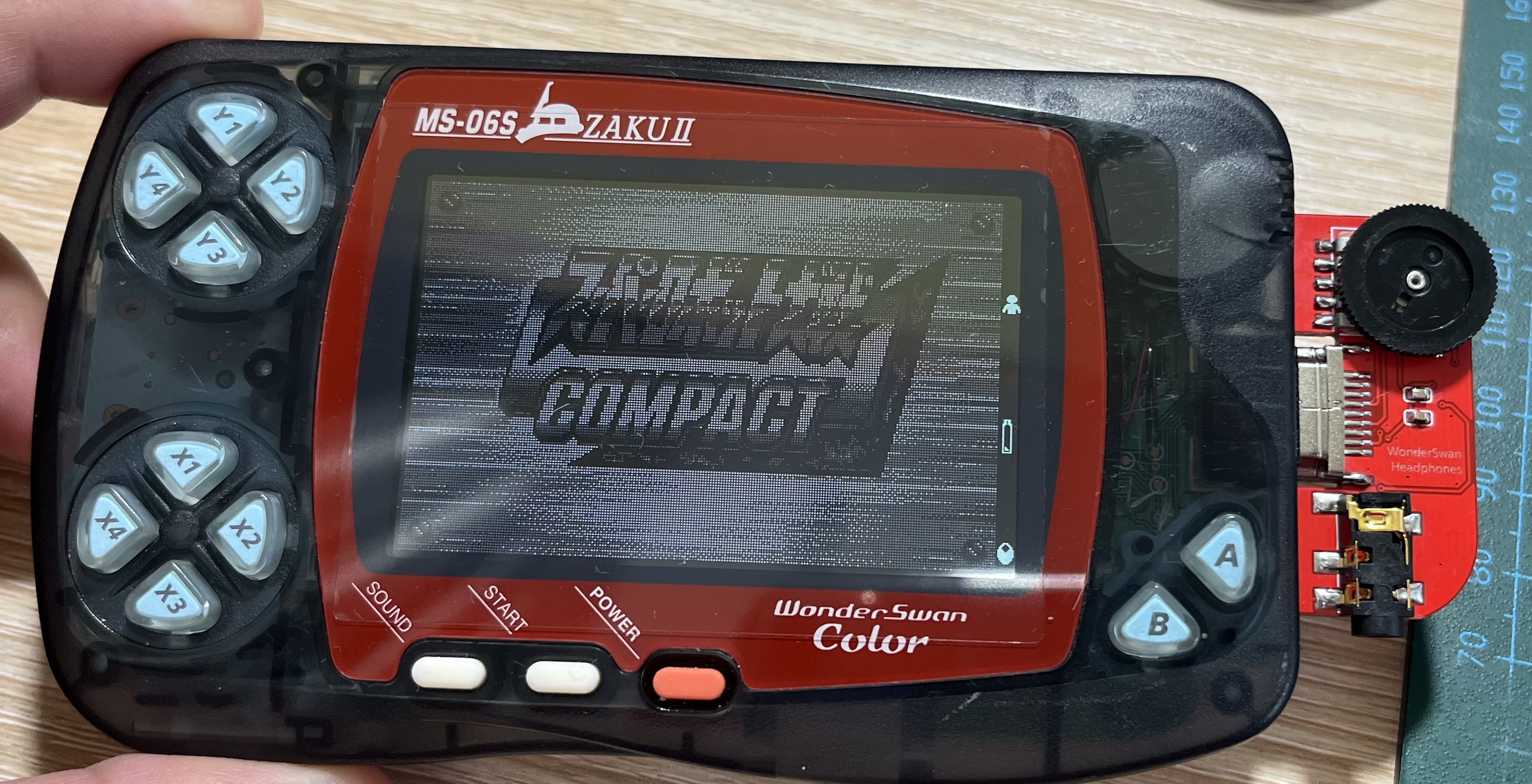
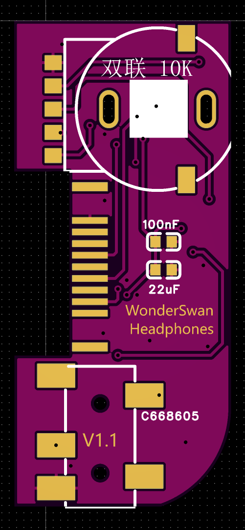
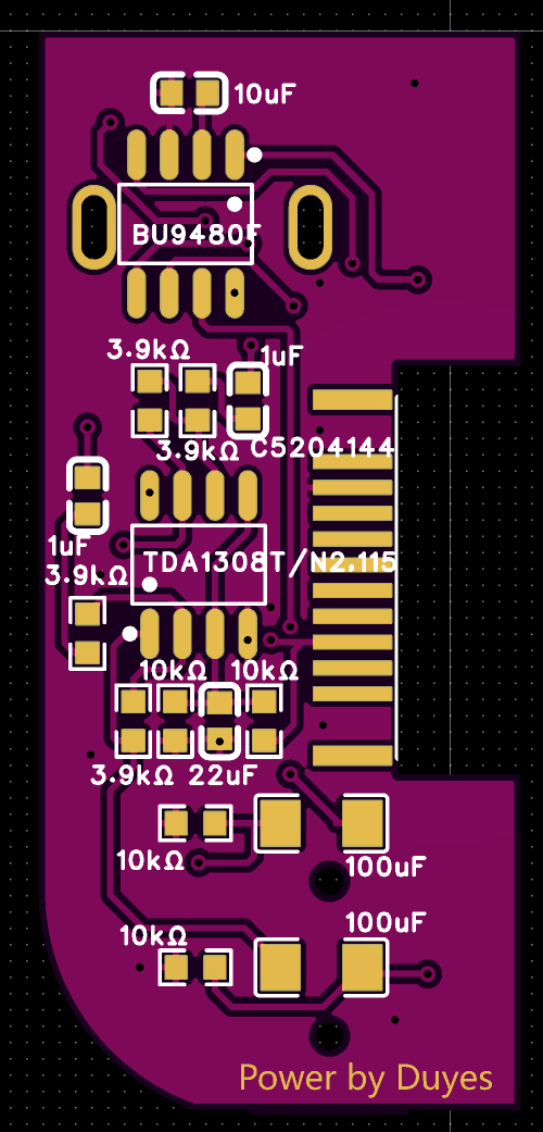
[Product tested] WonderSwan headphone adapter
Primarily, it provides headphone adapter functionality for the Bandai WonderSwan game console.
I haven't been playing with Game Boys much lately, switching to WonderSwans. Headphones can't be plugged in directly; you need an adapter.
I checked on Xianyu (a Chinese online marketplace), and there were quite a few. Original ones were too expensive, and DIY ones were okay, but I didn't like their looks.
After researching, I basically understand that a WonderSwan headphone adapter is just a digital-to-analog converter, converting the WonderSwan's digital signal into an analog signal.
So, I designed the board according to the datasheet. The first few boards I made had some issues, mainly with the HDMI plug selection. If it was too long, it would protrude too much from the device; if it was too short, it wouldn't make contact.
This is probably the third version, and it works perfectly now.
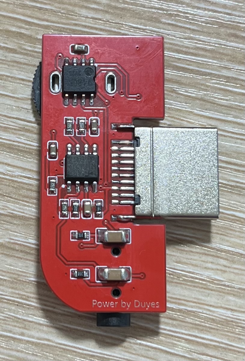
This open-source project doesn't plan to release the schematics or PCB layouts, only the Gerber manufacturing files from LCSC, because I saw boards on Xianyu being sold after various modifications.
Just use them directly. Choose a 5x5 QR code; otherwise, it will look bad for custom coders.
Try not to change the HDMI plug, as I've already specified the size; too long will look ugly.
The TDA1308 is not easy to find, but the domestically produced C2895052 can be used as a substitute.
I have removed all the silkscreen printing; just solder according to the picture.
Gerber_PCB1_2024-04-25.zip
PDF_【Physical Product Tested】WonderSwan Headphone Adapter.zip
Altium_ [Physical Product Tested] WonderSwan Headphone Adapter.zip
PADS WonderSwan Headphone Adapter (Physical Product Tested)
95082
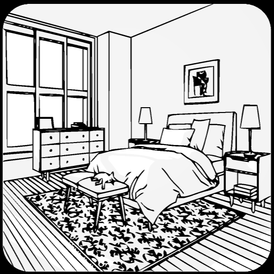
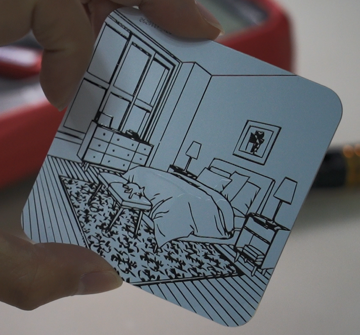
PCB light painting night light: a perfect combination of art and technology to illuminate the darkest path in life.
PCB light painting night light: a perfect combination of art and technology to illuminate the darkest path in life.
Foreword:
As an elderly person groping in the dark, I often stumble and fall. So, I made a small nightlight to illuminate my path.
You can watch the production video here:
https://www.bilibili.com/video/BV1PT42117uL/?vd_source=f19dbe714cbd76bd68c9603904fb336f
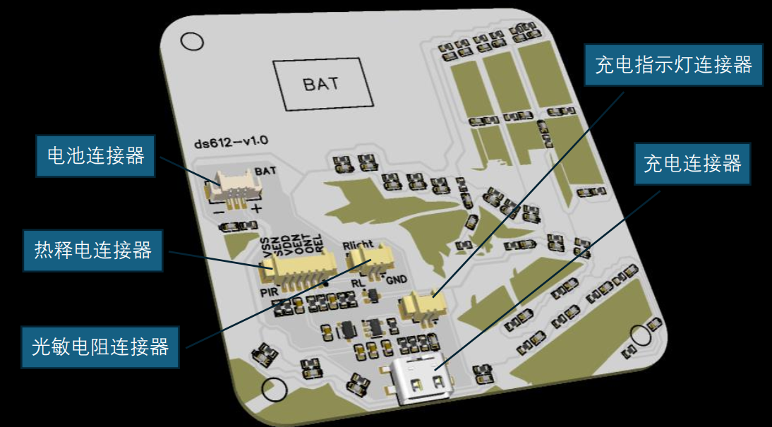
Schematic Diagram: The
schematic diagram mainly consists of three parts: power supply, sensors, and LEDs. The sensors include pyroelectric infrared sensors and photoresistors. All modules are connected using connectors. This project does not require software; all control logic is implemented in hardware.

PCB
: This is the third part of the PCB diagram. I spent a long time working on the window openings; my hands were trembling.
Actual Product:
This is the soldered circuit board. The yellow parts are the windows used for light transmission. Since the components are connected via connectors, you need to solder the wires yourself.

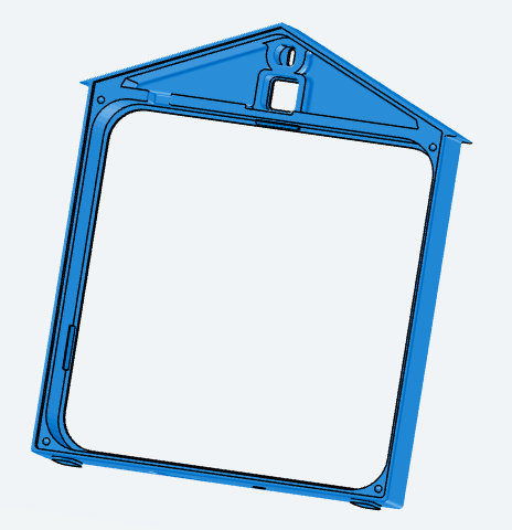
Casing:
I used 3D printing from FLCSC. It's best to choose an opaque material for the casing. After the casing is printed, a reflective film must be attached to the back panel during assembly; otherwise, the light will be uneven. The reflective film is simply a piece of white paper.
PCB Lighting Night Light DIY Guide.pdf
ds612_outer_v1.1.STL
ds612_cover.STL
PDF_PCB Light Painting Night Light: A perfect blend of art and technology to illuminate the darkest path of life.zip
Altium_PCB Light Painting Night Light: A perfect blend of art and technology to illuminate the darkest path of life. (zip file)
PADS_PCB Light Painting Night Light: A perfect blend of art and technology to illuminate the darkest path of life. (zip file)
BOM_PCB Light Painting Night Light: A Perfect Blend of Art and Technology to Illuminate the Darkest Path of Life.xlsx
95083
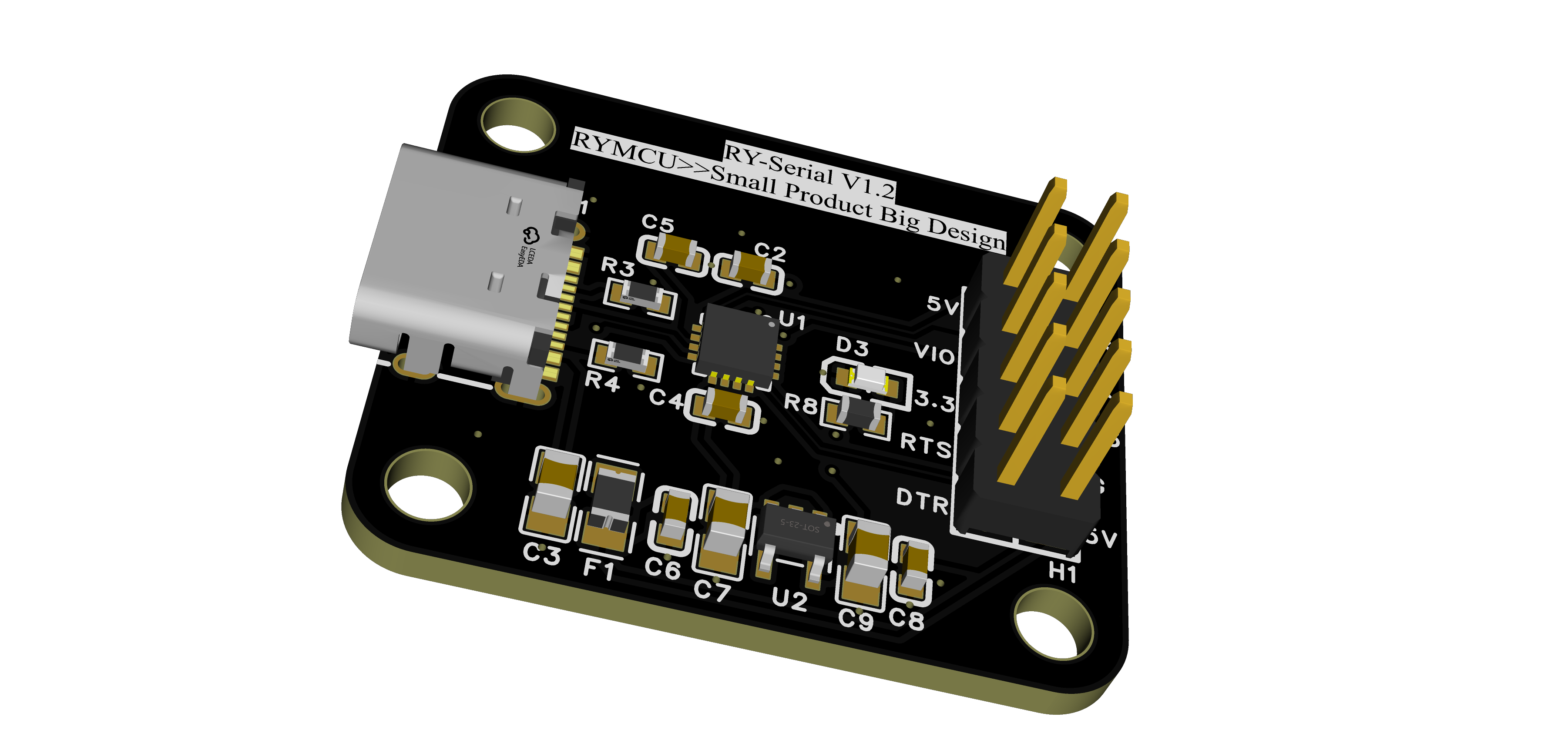
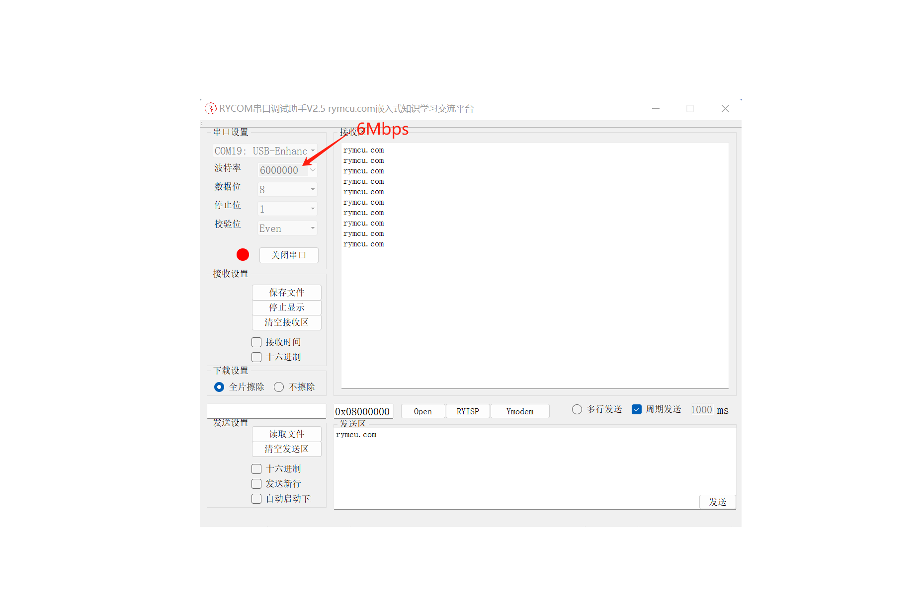
CH343P 6M High-Speed Serial-to-USB Module
RY-Serial is an open-source USB-to-serial module developed by the RYMCU community, with speeds up to 6Mbps.
RY-Serial is an open-source USB-to-serial module developed by the RYMCU community, with speeds up to 6Mbps.
Open-source project and documentation are available on:
GitHub
and Gitee.
The RYMCU
serial-to-USB module RY-Serial features
: 1) Uses the high-speed CH343P chip, with a maximum serial baud rate of 6Mbps;
2) Uses a USB Type-C interface for good versatility;
3) Windows compatible, no driver installation required;
4) Supports 5V and 3.3V level switching for the serial port;
5) Onboard self-resetting fuse for short-circuit protection;
6) Suitable for microcontroller serial port program downloading and debugging;
7) Supports CTS and RTS hardware automatic flow control;
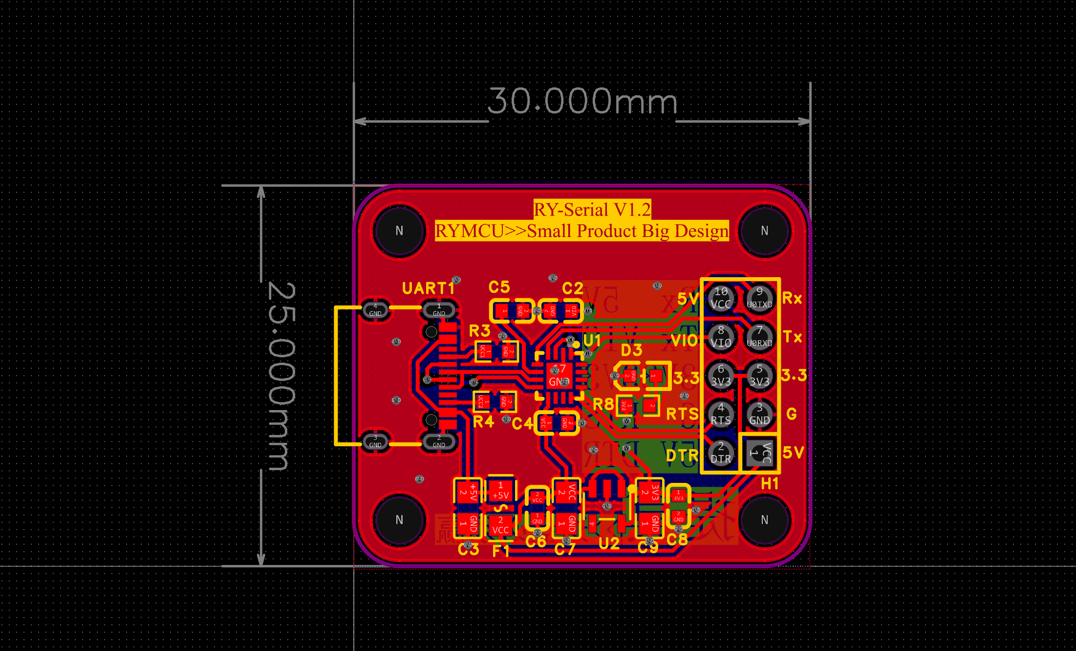
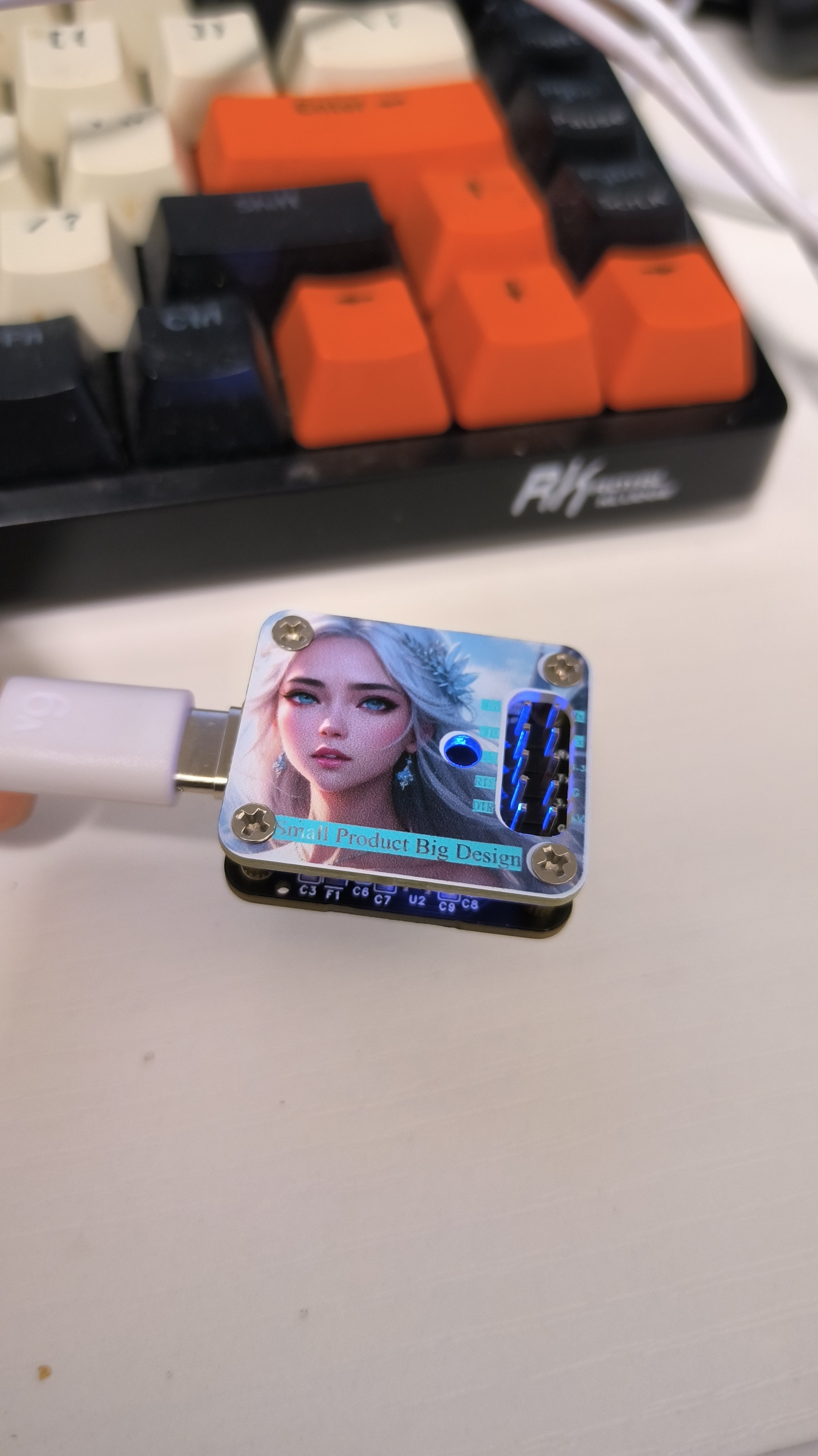
8) Compact size (2.5cm x 3.0cm) with powerful performance;
9) Color-printed cover plate for a beautiful and simple design;
10) Supports external power supply of 5V or 3.3V.

PDF_6M High-Speed Serial Port to USB Module CH343P.zip
Altium_6M High-Speed Serial to USB Module CH343P.zip
PADS_6M High-Speed Serial to USB Module CH343P.zip
BOM_6M High-Speed Serial to USB Module CH343P.xlsx
95084
LCSC GD32E230 Expansion Learning Board
https://www.cnblogs.com/sunshine-jackie/p/16645522.html
This board
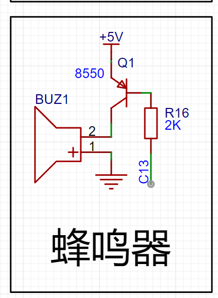
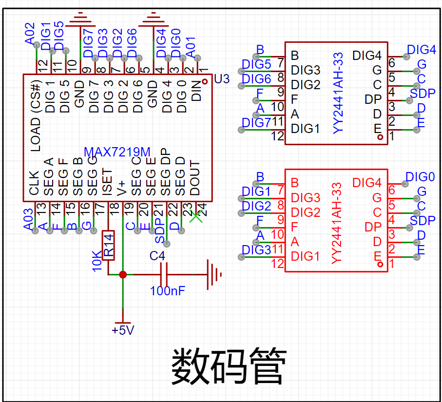
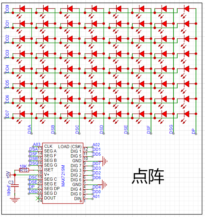
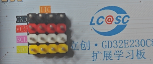
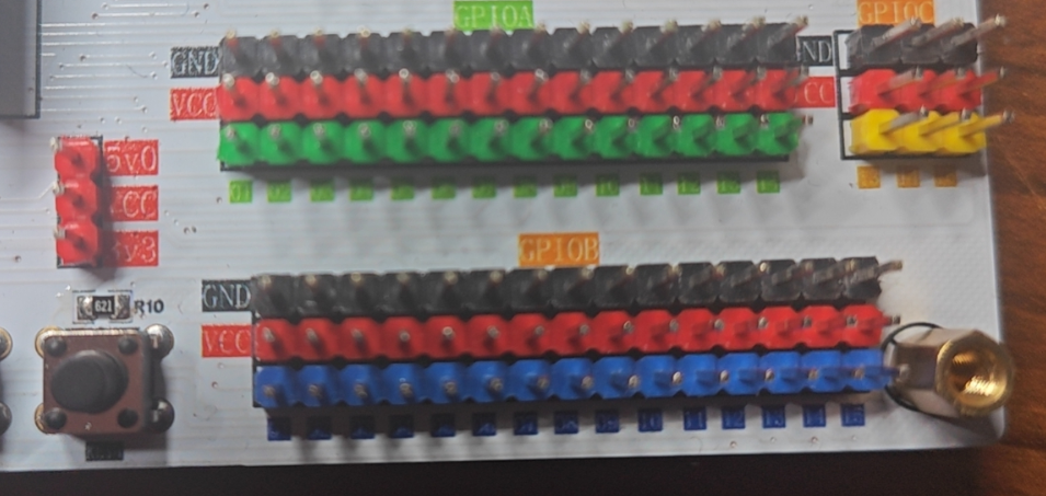
is an extension learning board for the LCSC GD32E230C8T6 development board. It integrates basic peripherals such as LED flashing lights, independent buttons, buzzer, digital tube, dot matrix, Bluetooth interface, screen interface, 2.4G interface, and all I/O are categorized and brought out, with 4 sets of IIC interfaces and dual power supply.
The board includes a physical image

and detailed specifications. It features dual
power
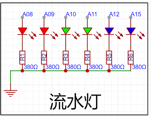
supply options: a Type-C 5V power supply or a DC 9-12V power supply. There are six LEDs for the

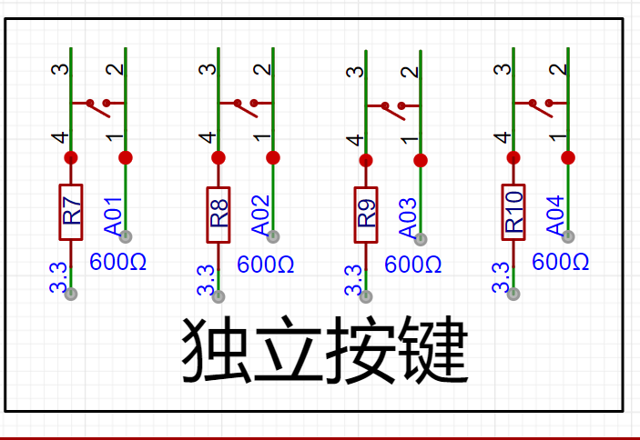
water lights , with the cathode connected to a 330Ω current-limiting resistor and then to GND. The positive terminals are connected to PA08, PA09, PA10, PA11, PA12, and PA15 . Four independent buttons are connected to A01, A02, A03, and A04, with the other end connected to 3.3V via a current-limiting resistor. The program uses a pull-up mode. The buzzer is driven by an 8550 NPN transistor, with C13 providing the signal. The signal can be observed through the LEDs on the core board. An 8-digit common cathode LED display (A01, A02, A03) is driven by a MAX7219, corresponding to DIN, CS, and CLK respectively. The dot matrix is also driven by a MAX7219. These correspond to the DIN, CS, and CLK screen interfaces respectively. An 8-bit SPI interface can be used, or the first 4 bits can be used as an IIC interface for Bluetooth connection to the HC-05 Bluetooth module 2.4G. The 2.4G module interface connects to the 2.4G module IIC . There are 4 groups of IIC interfaces to meet your needs. The VCC voltage is selected under the jumper on the left side of the GPIO . All GPIO pins are represented by green, blue, and yellow, respectively, and are numbered below. Red pins connect to VCC, and black pins connect to GND. Usage Help: LED Experiment , Button Experiment, Buzzer Experiment, Serial Port Experiment, Screen Interface, Bluetooth Interface. Bug Fix Record 2024.04.24: Silkscreen Errors : GPIOA numbering was incorrectly written as 01~14, GPIOB numbering was incorrectly written as 01~15. This has been corrected, and the font size has been enlarged based on the sample.


PDF_LCSC GD32E230 Extended Learning Board.zip
Altium GD32E230 Extended Learning Board.zip
PADS_LCSC GD32E230 Extended Learning Board.zip
BOM_LCSC GD32E230 Extended Learning Board.xlsx
95085
USB flash drive
A USB flash drive made with GL823K-HCY04 and Genesis SD SAND storage, plug and play.
This is a USB flash drive made with a GL823K-HCY04 and Genesis SD NAND storage. It's plug-and-play and includes a casing. Those with a printer can export and print the data. The Genesis chip, although advertised as 4GB, doesn't mean it has over 4000MB of storage. It has a unit; I selected 4GB, and it showed over 480MB. If you want to use it properly, choose a larger capacity, like 32GB, which would be close to a true 4GB capacity, but it's not cost-effective as it's quite expensive. It's better to use eMMC. Note that the casing in the project doesn't have screws; don't forget to add screws if you're making a replica.
_4[LMQ0`UZ625PI11`RDJAP.jpg
`$5AXWY8[YOKBHKE$B(4PO4.png
0UE]XAH[YD@)NC@8JS0D%7L.jpg
9$Q6K`)G~J2O4]XFTH(MD{T.png
1713969762995.jpg
PDF_USB Flash Drive.zip
Altium_U disk.zip
PADS_U disk.zip
BOM_USB drive.xlsx
95086
electronic


 京公网安备 11010802033920号

 5082-A403-LJ000


