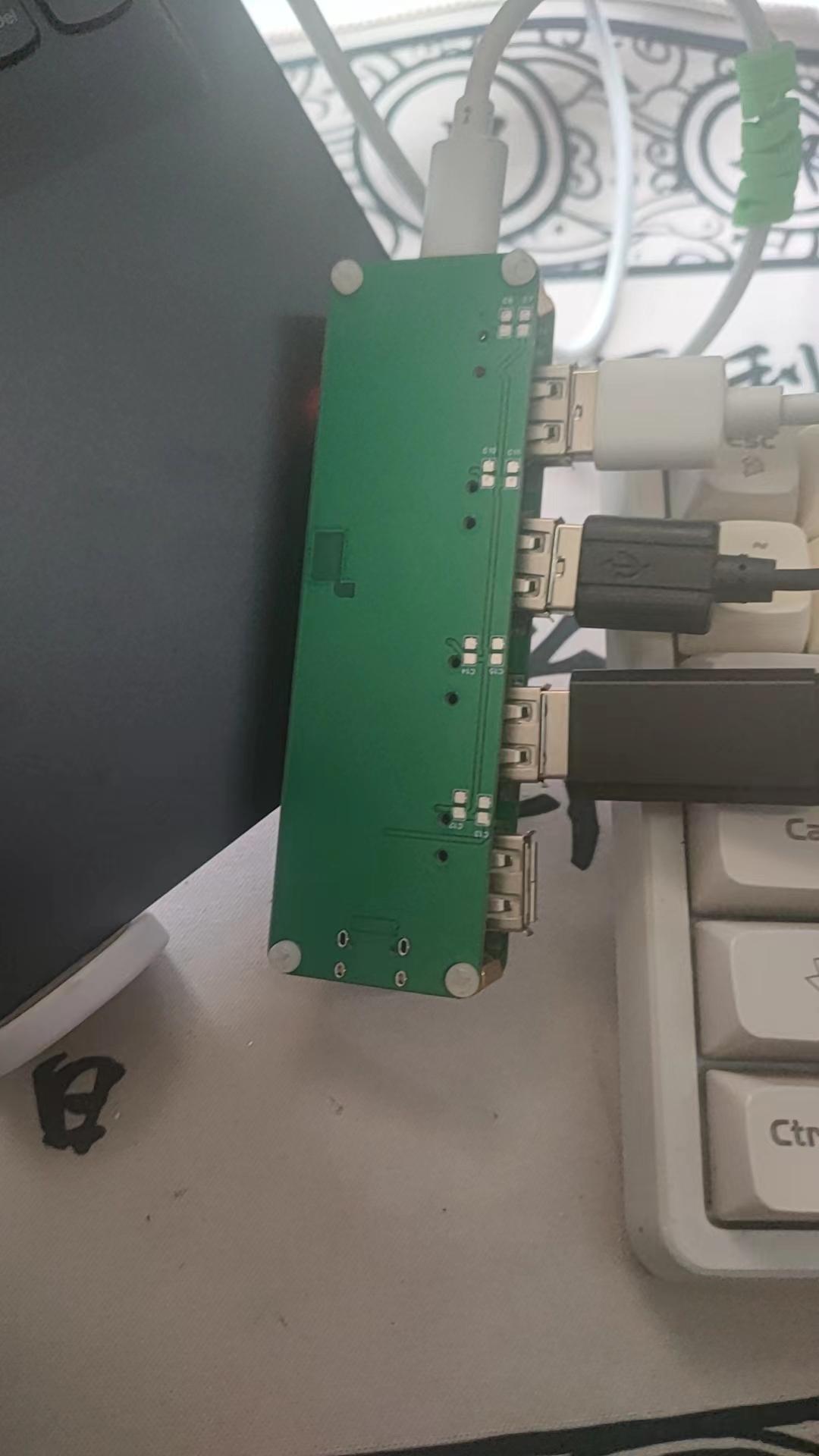
The SL2.1A chip acts as an adapter, connecting to an external 12MHz crystal oscillator. It includes a fuse to prevent overcurrent, a power indicator light, and is a 1-to-4 USB expansion dock. It also features hexagonal copper pillars and screws (don't forget to buy those too). In the end, it looks really cool.
PDF_USB Dock.zip
Altium_USB Dock.zip
PADS_USB Dock.zip
BOM_USB Dock.xlsx
95184
2.7V or 6V spot welding machine supercapacitor version can spot weld copper up to 0.2mm thick.
ESP32 Spot Welding Machine: Split-type Dual-purpose Supercapacitor Spot Welding Machine
This project is modified from "The Light of Entropy: Portable Spot Welding Machine 2.1", open source address: https://oshwhub.com/fj956391150/pian-xie-dian-han-ji.
Product Introduction:
The TYPE-C interface is mainly used for programming ESP32 C3 and charging the device (5V/2A).
It features a TYPE-C-->supercapacitor input 7.5W (5V/1.5A) constant power charging circuit and a lithium battery-->supercapacitor maximum output 0.8A constant current charging circuit, and can independently control the switch.
It supports the acquisition and display of parameters such as USB voltage, battery voltage, capacitor voltage, and weldment detection voltage and temperature.
0.96-inch ST7735 The 160*80 display shows various parameters,
three buttons for mode switching and parameter setting control, and a toggle switch for power on/off control.
It features a supercapacitor current backflow prevention circuit to reduce capacitor standby leakage
current. It supports automatic and manual spot welding modes and allows setting multi-pulse welding time and number of welds. It also
includes various function switches, parameter settings, over-temperature protection, and under-voltage protection.
--------------------From here on, I will explain the modifications to this version---------------
The continuous spot welding function has been removed; only a dual-pulse mode is available, controlled by preheating pulses and pulse duration.
If the main control board uses a 3V 3000F capacitor, the auxiliary power function can be disabled, including not soldering some components on the main board.
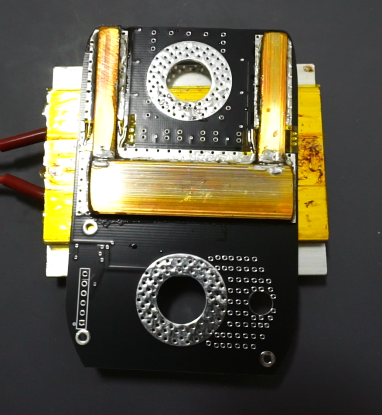
The power board uses 12 40V 600A MOSFETs. One 15*55mm copper busbar is used for backflow, and the other two narrower ones are 15mm copper busbars cut in half. Alternatively, 6mm wide busbars can be purchased separately.
35mm flat wire is used, and the soldering pins are 3.2mm copper rods with ground tips.
Supercapacitors can be found at seafood markets. Both 2.7V and 3V are acceptable. Note the stud thickness. The PCB in this project has 12mm openings.
Discussion group: 200165775.
My test video is available on Bilibili; it's the latest video posted by "Mr. Cheese".
IMG_1692.MP4
IMG_1694.MP4
PDF_2.7V or 6V spot welding machine with supercapacitor version, capable of welding copper up to 0.2mm thick.zip
Altium 2.7V or 6V spot welding machine supercapacitor version can spot weld copper up to 0.2mm thick.zip
PADS_2.7V or 6V spot welding machine supercapacitor version can spot weld copper up to 0.2mm thick.zip
BOM_2.7V or 6V spot welding machine supercapacitor version can spot weld copper up to 0.2mm thick.xlsx
95185
IRON_MAN2
Simple touch-sensitive lights mimic Iron Man's reactor.
The TTP223N is used to control the power and off status of LED lights, and the touch sensitivity is achieved by changing the values of capacitors and resistors in the external circuit.
video(1).mp4
SCH_IRON_MAN2_2024-04-16.json
PCB_PCB_IRON_MAN2_2024-04-16.json
BOM_IRON_MAN2.xlsx
95186
Desktop charging station
DC fast charging, supports three input interfaces: DC5-2.5, PD fast charging. Outputs include one voltage regulation output, one USB-C multi-protocol fast charging output, and one USB-A multi-protocol fast charging output. Charging information is displayed on the touchscreen.
Having learned about JLCPCB hardware for so long, I'm finally contributing to JLCPCB's hardware community!
The input PD fast charging uses a 224kbps input as a decoy. The other two ports utilize a discarded computer charger, so they use the most common Lenovo square port and DC 2.5, meaning only one input port can be used at a time.
Fast charging output:
Supports PD 2.0/3.0 and PPS
, supports Quick Charge 3.0+/3.0/2.0 protocols - supports Xiaomi Charge Turbo 27W protocol, Huawei FCP/SCP/HVSCP protocols, Samsung AFC protocol, USB BC1.2 DCP, and Apple 2.4A charging specification
to adjust the maximum output current to 3A.
Each output port uses an INA226 to detect charging information.
The touchscreen is driven by an STM32 microcontroller and LVGL library.
Reserved: One PWM port, one ADC detection port, and one 7-pin 2.54 port for connecting to a DWIN serial touchscreen.
Reserved: One 4-pin 2.54J interface for 3.3V and 5V power output.
Reserved: One 4-pin 2.54 interface for microcontroller downloading and debugging.
A simple usage video is attached.
Project code upload failed; contact me if you need it.
9de26077f34cb2ba30722a194dc7b013.mp4
PDF_Desktop Charging Station.zip
Altium Desktop Charging Station.zip
PADS Desktop Charging Station.zip
BOM_Desktop Charging Station.xlsx
95187
T113_MIPI
T113 MIPI Touchscreen Core Board
This core board is compact in size and boasts abundant onboard resources. All components are located on one side, while the back can be directly connected to a 3-inch MIPI LCD screen via an FPC cable. Onboard components include a CH340, MPU6050, hub, NAND flash, microphone, and XR829-WIFI. This core board can be debugged using only a single Type PC cable, making it extremely convenient. The debugging serial port, ADB interface, audio interface, USB, and GPIO are all brought out. It offers excellent expandability. All onboard resources have been tested and are working correctly.
LVGL.mp4
TCP image transmission.jpg
Tplaydemo.mp4
MPU6050 test.mp4
QT test.mp4
PDF_T113_MIPI.zip
Altium_T113_MIPI.zip
PADS_T113_MIPI.zip
BOM_T113_MIPI.xlsx
95188
One-channel and seven-channel grayscale tracking modules
This project consists of a single-channel grayscale tracking module and a seven-channel tracking module, using the LM393 as the core and employing photodiodes and LEDs to achieve the tracking effect. The circuit design is based on the TCRT5000 circuit drawn by experts on the open-source forum.
Grayscale tracking has been verified and works normally.
This module contains one single-channel grayscale tracking module and one seven-channel grayscale tracking module. This module was designed when I first started learning PCB design, and some routing may be unreasonable; please refer to it with caution.
The grayscale tracking module works correctly after soldering. LEDs marked with "Light Emitting Diode" are used to solder LEDs (the light color depends on the map background to be identified; white LEDs are commonly used). Photodiodes are used to solder photodiodes (i.e., photodiodes) to LEDs marked with "Photodiode".
It is recommended to wrap the LEDs and photodiodes with equal-length black heat shrink tubing before soldering.


710b1e941ba0fa403c4d79cceba3bd3d.mp4
PDF_One-way and Seven-way Grayscale Tracking Module.zip
Altium_one-channel and seven-channel grayscale tracking module.zip
PADS_One-channel and Seven-channel Grayscale Tracking Module.zip
BOM_One-way and Seven-way Grayscale Tracking Module.xlsx
95189
Raspberry Pi Expansion Board
1.47-inch ST7789V3 + 4 buttons + 4 LEDs
I designed a Raspberry Pi debugging expansion board based on my actual needs. I wrote some Python scripts to help testers who are not computer literate configure test debugging and save log output.
test.zip
PDF_Raspberry Pi Expansion Board.zip
Altium_Raspberry Pi Expansion Board.zip
PADS_Raspberry Pi Expansion Board.zip
BOM_Raspberry Pi Expansion Board.xlsx
95190
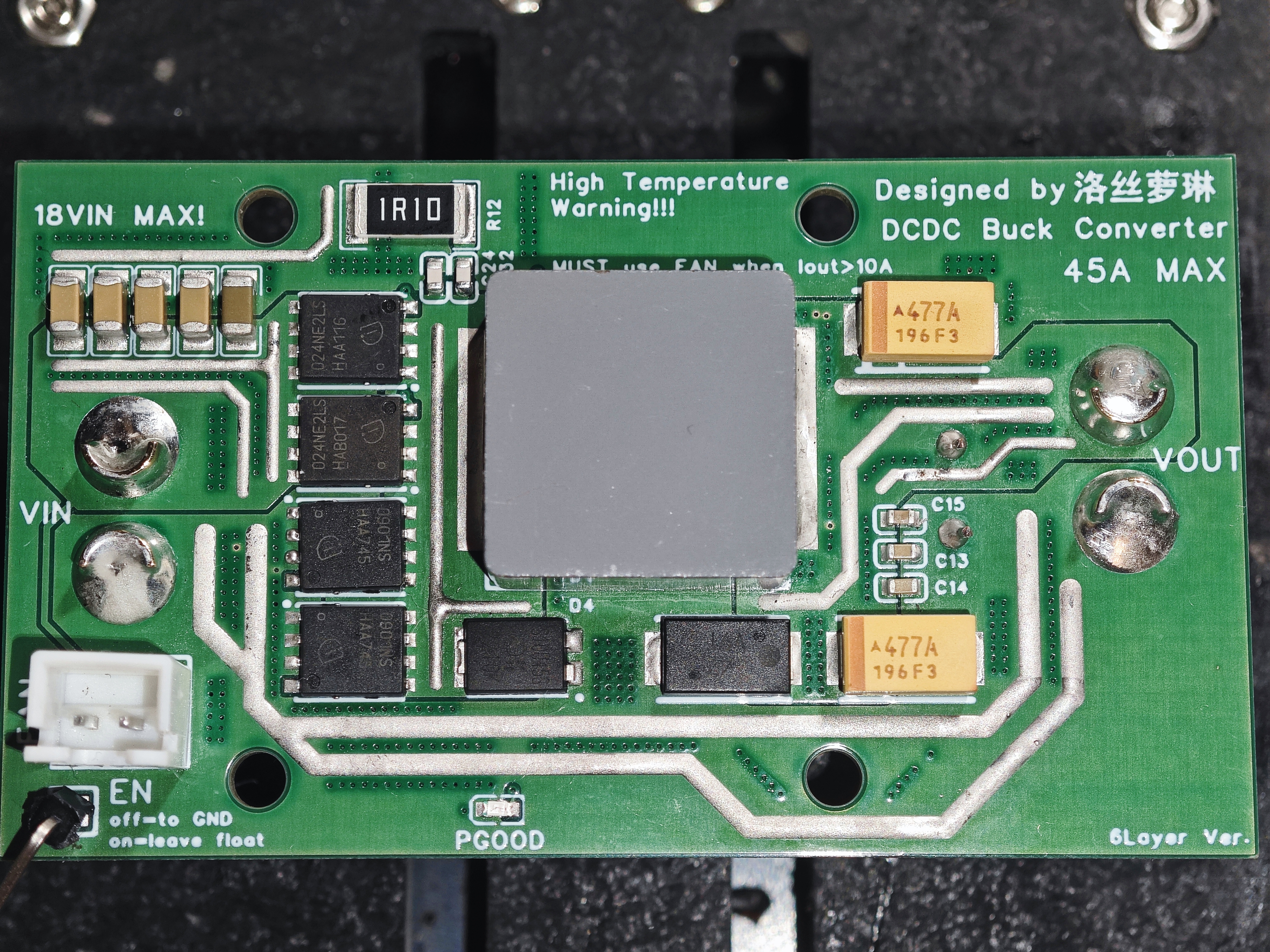
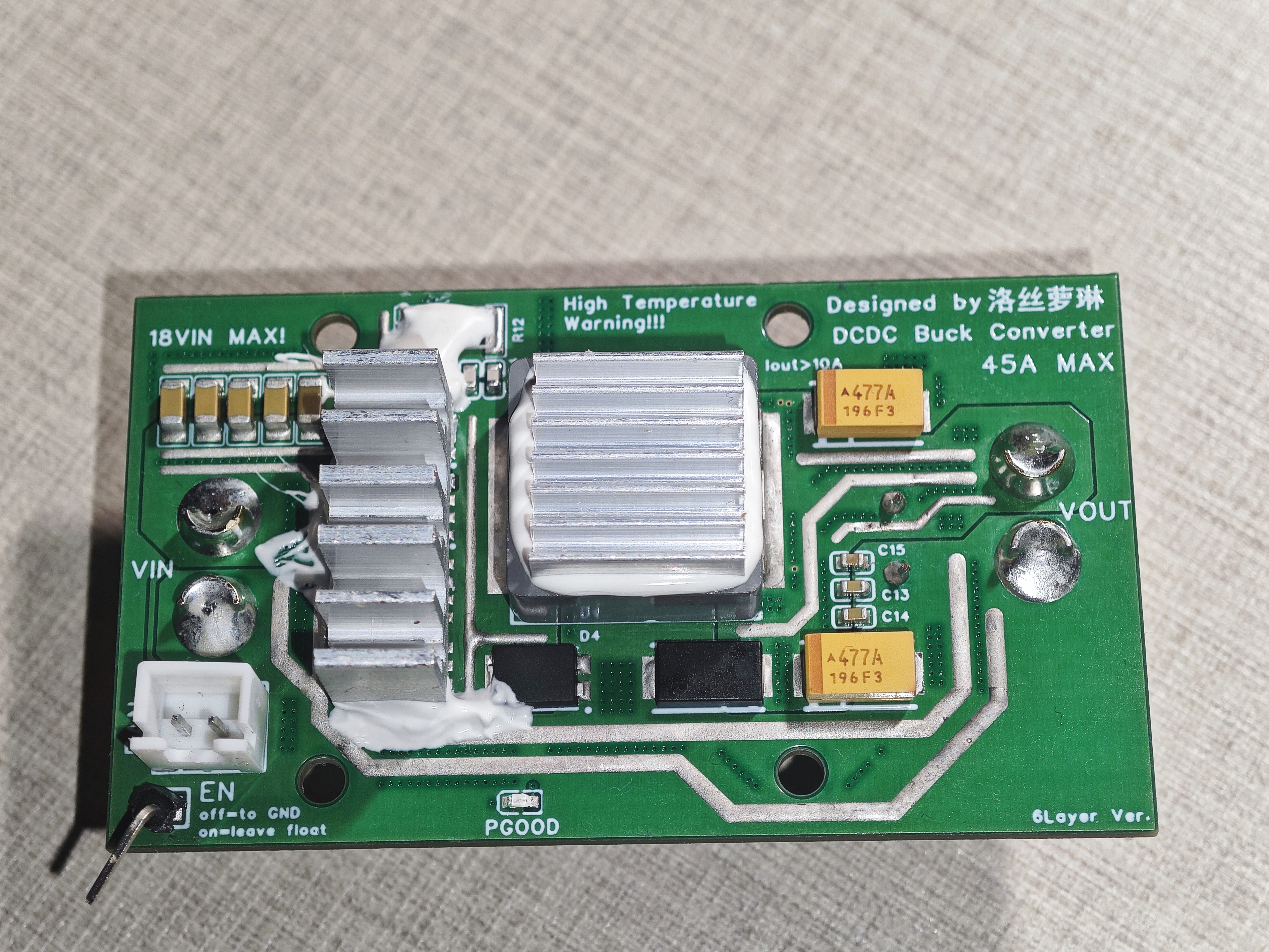
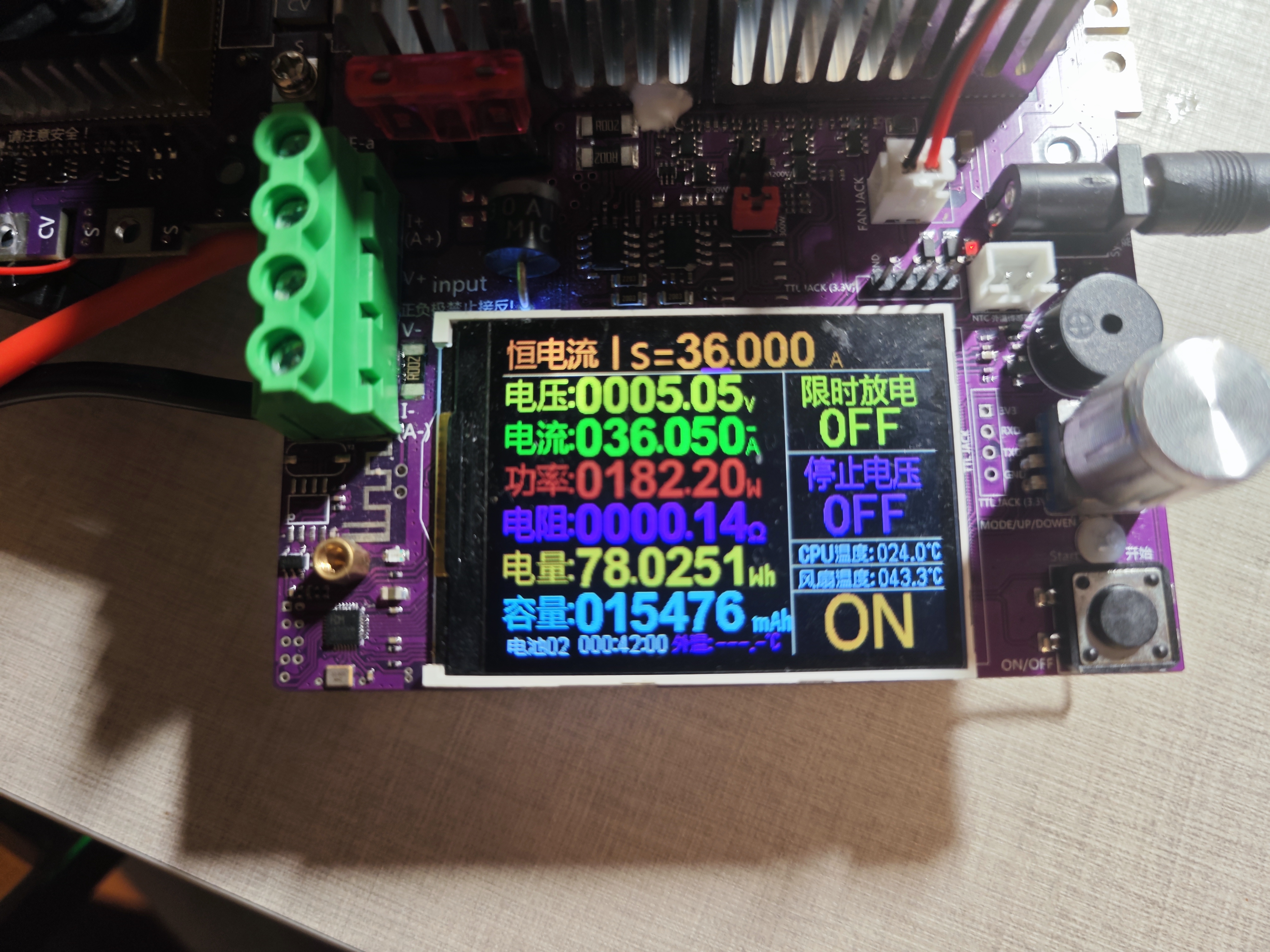
[Tested] 12V Input 45A Output DC-DC Step-Down Module
This compact, high-power, high-density DC/DC step-down module features a 10V-18V input, 0.8V-5.5V output, peak output current of 45A, and continuous output current of 40A. It also includes a fan interface and an external shutdown signal function.
(Successful board soldering tests have verified the usability of this solution: V1, V2)
Module Specifications (V2 version only):
Utilizes Infineon OptiMOS™ Power MOSFET power devices
in a compact 70*40*25mm form factor (including active thermal design).
Wide input voltage range of 10V-18V, wide output voltage range of 0.8V-5.5V.
Peak output current up to 45A, continuous output current of 40A.
Conversion efficiency ≥94% at 40%-100% load.
Ripple less than 100mV across the entire load range, only 20mV at no load.
Integrated active thermal design and power-on indicator.
Externally controllable EN shutdown signal.
Module Specifications (V1 version only):
Utilizes Texas Instruments NexFET™ integrated half-bridge power devices.
Compact 70*40*25mm form factor (including active thermal design). Wide
input voltage range of 10V-15V, wide output voltage range of 0.8V-5.5V.
Peak output current up to 35A, continuous output current of 30A.
Conversion efficiency ≥ 96% at 40%-100% load.
Ripple less than 100mV across the full load range, and only 20mV under no-load.
Integrated active cooling and power-on indicator.
Externally controllable EN shutdown signal.
Chip Information:

Notes:
Active cooling is recommended for continuous currents greater than 10A, and is mandatory for currents greater than 15A!
Power MOSFETs and inductors require additional aluminum heatsinks. Fan dimensions are shown in the schematic (heatsink and fan installation diagrams are provided in the physical sample).
Input and output directions must not be reversed! The positive and negative terminals of each connector must not be reversed!
For outputs greater than 20A, it is recommended to add sufficient MLCCs and electrolytic capacitors at the load end.
The PCB layout with open windows requires soldering.
The project includes 4-layer and 6-layer PCB files; please use
the physical sample (V2) as needed.
Note: Except for the XT60 connector, other areas use silver-containing lead-free solder, so the solder joints are matte.


PDF_【Tested】12V Input 45A Output DC-DC Step-Down Module.zip
Altium [Tested] 12V Input 45A Output DC-DC Step-Down Module.zip
PADS - [Tested] 12V Input 45A Output DC-DC Step-Down Module.zip
BOM_【Tested】12V Input 45A Output DC-DC Step-Down Module.xlsx
95191
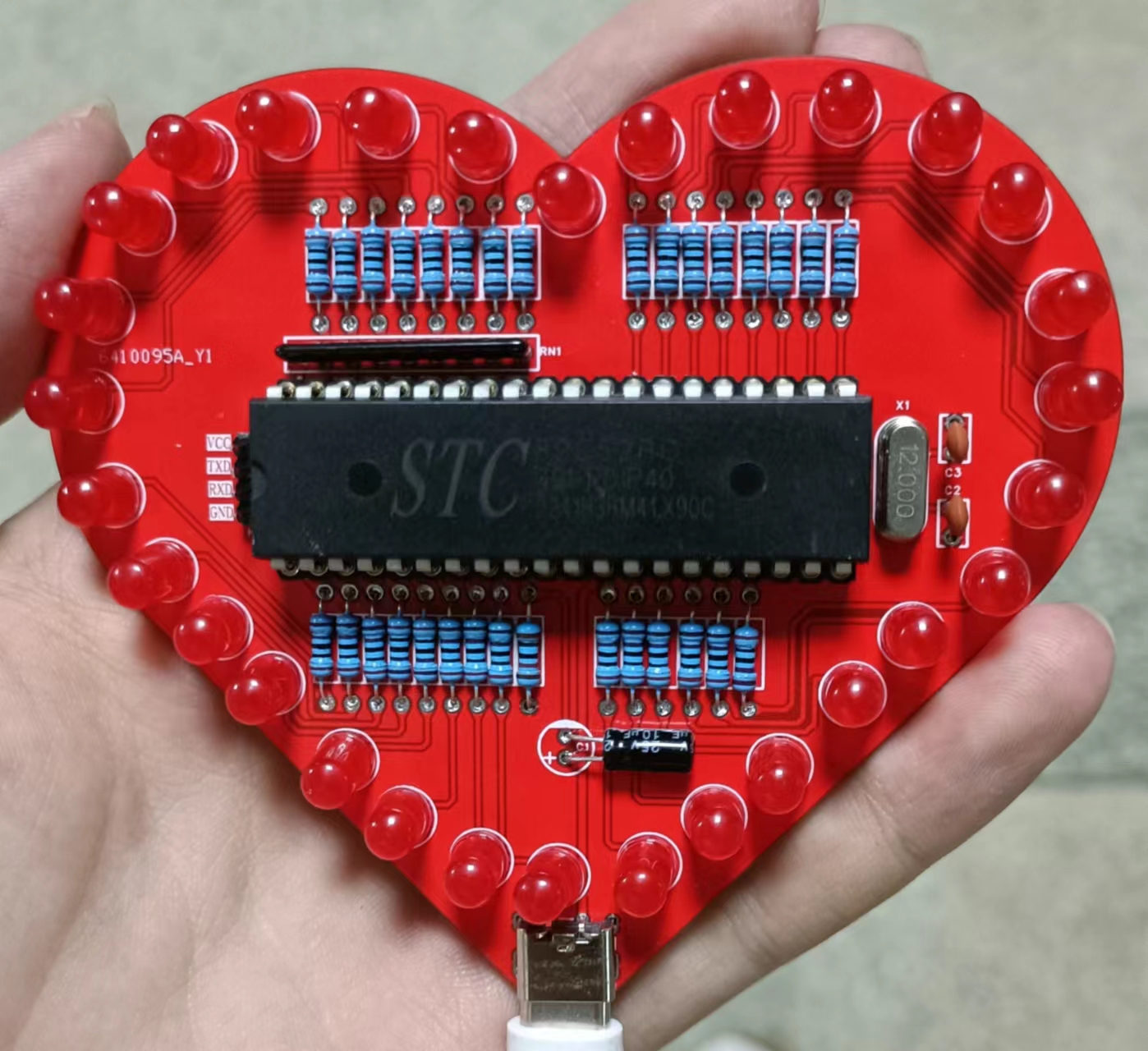
Heart-shaped flowing water lamp
This project was my first project during my freshman year when I started learning JLCPCB EDA. At that time, I followed the LCPCB EDA videos on Bilibili to draw the schematics and PCBs, and I benefited a lot from it.
Note!!! This project was copied and pasted from another project (I was too lazy to redraw it). There might be some issues when converting from schematic design to PCB, but the connection between the schematic and PCB is absolutely fine (I can't guarantee the routing is up to standard). It has been verified in a physical device. The program source code is referenced from Bilibili user: Xiaobaiyun's Bilibili video (released April 3, 2023, titled "Flowing Lights"). (Contact me to remove if there is any copyright infringement). The attached file contains the HEX file of the program from the video; after downloading, you can directly use STC-ISP to burn it into your microcontroller.
WeChat_20240416220506.mp4
heart_lamp.hex
PDF_Heart-shaped Flowing Water Lamp.zip
Altium_Heart-shaped Flowing Light.zip
PADS_Heart-shaped Flowing Light.zip
BOM_Heart-shaped Flowing Light.xlsx
95192
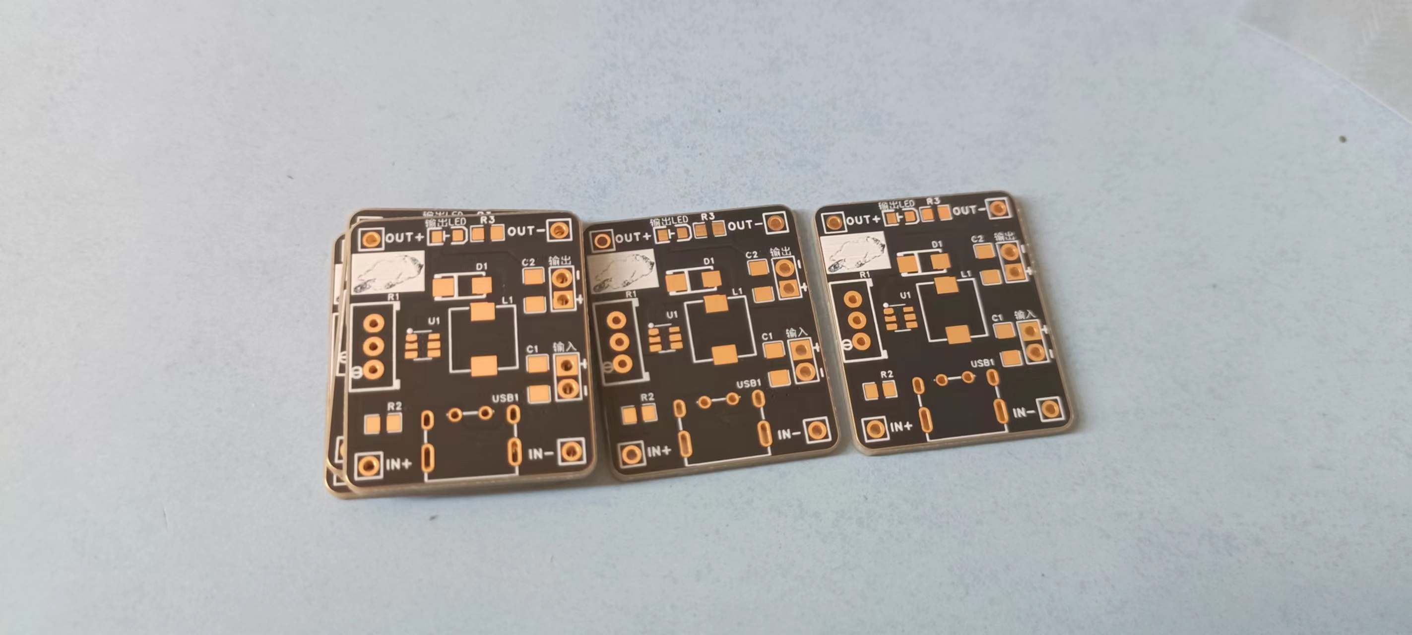
MT3608 boost module
The wiring layout of an MT3608 boost module may not be standard; please refer to it with caution.
The actual product has been tested and verified to be usable. The 100kΩ sliding rheostat in the circuit diagram can be replaced with a 10kΩ rheostat. Please adjust the voltage boost rate according to your needs.
PDF_MT3608 boost module.zip
Altium_MT3608 boost module.zip
PADS_MT3608 boost module.zip
BOM_MT3608 boost module.xlsx
95193
electronic


 京公网安备 11010802033920号

 ADM8617RACYKS-RL7


