I. Hardware Circuit Analysis
A digital oscilloscope is an instrument used to display electrical signal waveforms. It consists of several key circuits, each playing a crucial role. In this project, the main circuits involved include the power supply circuit, microcontroller circuit, analog front-end circuit, comparator frequency measurement circuit, screen driver circuit, button control circuit, and indicator circuit.
1.1 Analog Front-End Processing Circuit The
analog front-end processing circuit is the core of the digital oscilloscope, responsible for processing the input analog signals. Among them, the AC/DC coupling selection circuit adapts to different signal inputs; the voltage attenuation circuit adjusts the signal amplitude; the signal processing circuit further amplifies, filters, and conditions the signal; and the frequency detection circuit measures the signal frequency to aid sampling and display.
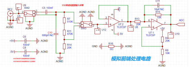
Figure 1 Analog Front-End Processing Circuit
1.1.1 AC/DC Coupling Switching Circuit
Signals are divided into two main categories: DC and AC. However, in practice, this is often imperfect. DC power signals are not flat due to ripple, and AC signals may also contain DC components, affecting measurements. To accurately measure AC signals, the characteristic of a capacitor that allows AC to pass while blocking DC can be utilized. A series capacitor filters the DC component, i.e., AC coupling. DC coupling, on the other hand, retains all signal components.

Figure 2 shows the AC/DC coupling switching
circuit. A toggle switch SW2 switches the input AC/DC coupling signal. When switch 2 is connected to switch 1, it's DC coupling; when switch 2 is connected to switch 3, it's AC coupling. When DC coupling is applied, the current path is a wire, and no additional processing is done on the input signal. When the circuit is AC coupling, the capacitor connected in series in the circuit has the characteristic of blocking DC and passing AC, so the DC component cannot pass through the branch containing the capacitor and is therefore filtered out at the front end of the circuit, thus not affecting the subsequent AC signal processing.
1.1.2 Input Signal Attenuation
Circuit After passing through the AC/DC coupling switching circuit at the front end, the signal enters the input signal attenuation circuit. SW3 allows us to select one of the two channels as the input. When switches 1 and 2 are connected together, the input voltage enters the voltage follower directly without going through the resistor divider. When switches 2 and 3 are connected together, the input voltage, after being divided by R7, R11, and R12, enters the voltage follower at the back end, which is the voltage across R14. By calculating R14/R7+R11+R14=1/50, we can conclude that the actual input voltage to the back end should be 1/50 of the input voltage to the front end, meaning the signal is attenuated to 1/50 of its original value.
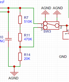
Figure 3 Input Signal Attenuation Circuit
1.1.3 Signal Conditioning Circuit
Virtual Short: When the operational amplifier is in a deep negative feedback state, a phenomenon called "virtual short" occurs. The essence of this phenomenon is that the potentials of the two input terminals are almost the same at this time, as if they are short-circuited together. Therefore, we can approximately consider the voltage at the positive input terminal (V+) to be equal to the voltage at the negative input terminal (V-), that is, V+ = V-.
Virtual Open: In the design of an ideal operational amplifier, its input impedance is set to infinite, meaning that theoretically, no current should flow through the input terminal. However, in practical applications, the actual input impedance of the op-amp is finite, although it may be very large.
This phenomenon of almost zero input current is called "virtual short". It reflects the high input impedance characteristic of the op-amp design, so that in practical applications, the input of the op-amp has minimal impact on the external circuit, thus ensuring the stability and accuracy of the op-amp.
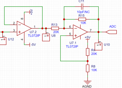
Figure 4 Signal conditioning circuit
(1) Voltage follower
As we can see from Figure 4, the inverting input pin 2 of the U7.2 chip op-amp is connected to the output of the op-amp (pin 1), and the non-inverting input pin 3 is connected to the front-end circuit. According to the concept of virtual short of the operational amplifier mentioned above, V+ = V-. It can be seen that the voltage on the inverting input pin of the voltage follower will be equal to the voltage on the non-inverting input pin, and the inverting input pin is directly connected to the output of the op-amp, so the voltage at the output of the op-amp is the non-inverting input voltage, and the amplification factor is 1.

Figure 5 Voltage follower
Then some people may ask, isn't the existence of the voltage follower redundant? Wouldn't it be easier to just connect it to the subsequent circuit with a wire?
The voltage follower plays the role of signal buffering and impedance matching in the circuit. It connects the front and rear stage circuits to achieve electrical isolation and prevent mutual interference. At the same time, the high input impedance and low output impedance of the voltage follower can match the impedance between different circuits, reduce signal loss, and maintain low distortion in signal transmission.
(2) Proportional
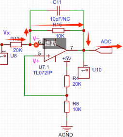
amplifier circuit 6 Proportional amplifier circuit
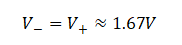
Similarly, when facing the proportional amplifier circuit, we also start the analysis directly from the characteristics of virtual short and virtual open of the op-amp. We first see the positive input pin of the op-amp. V+ is the voltage dropped on R8 after the +5V voltage is divided by R4 and R8. Therefore:

According to the concept of virtual short of the op-amp:
Since the op-amp has virtual open, we can regard the connection between R13 and the inverting input pin of the op-amp as an open circuit. Then R13 and R15 are connected in series. Let the input voltage at the left end of R13, that is, the voltage input to the preamplifier circuit, be Vx. Let the voltage input to the microcontroller pin from the proportional amplifier circuit be Vo. The microcontroller's GPIO can generally tolerate a voltage of 0V~3.3V, that is, the acceptable range of Vo is 0V~3.3V.
Then we list the formula:

Substitute the data to calculate:
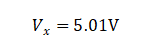
(1) When Vo = 0V:
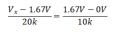
Solve for:
(2) When Vo = 3.3V:
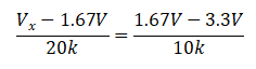
Solve for:

Therefore, within the range that the microcontroller's ADC pin can tolerate, and without attenuating the input signal, the measurement range is approximately -1.6V~5V. If the signal is attenuated, it should be multiplied by the corresponding factor 50, that is, the measurement range is expanded to -80V~250V.
Summary: Low voltage range: -1.6V~5V; High voltage range: -80V~250V.
In fact, the two independent operational amplifiers constituting the voltage follower and proportional amplifier are integrated on a single 8-pin integrated chip. They are two independent operational amplifiers, sharing positive and negative power inputs, even though they are on the same chip.
1.1.3 Comparator Frequency Measurement Circuit.
We know that there are many types of signal waveforms. Common signal waveforms include square waves, sine waves, triangle waves, etc. However, the input capture function of a microcontroller detects the rising or falling edge of a waveform. To capture the waveform and obtain higher accuracy, we can process the signal waveform and convert it into a square wave for easier and more accurate measurement. To achieve waveform conversion, we can use a Schmitt trigger to process the signal waveform:
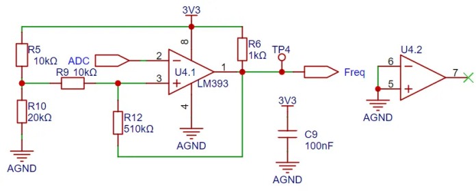
Figure 7 Comparator Frequency Measurement Circuit.
First, we need to understand the characteristics of a comparator. A voltage comparator is usually used to compare the magnitudes of two input voltages and output a corresponding high or low level. It is often used to determine the threshold of a signal, generate digital logic signals, or trigger the operation of other circuits. The output of a voltage comparator is discrete, with only two possible states, typically high or low. If the voltage at the non-inverting input pin is higher than that at the inverting input pin, the comparator will output a high level; otherwise, it will output a low level.
To analyze the working principle of the Schmitt trigger circuit, we need to set its initial output state.
(1) Assuming the initial output level of the comparator is high, the equivalent circuit diagram is as follows:
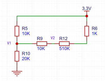
Figure 8 Initial high level Schmitt trigger
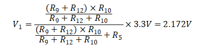
When the initial level of the comparator is high, the original circuit diagram can be simplified to Figure 7. The voltage V+ of the non-inverting input pin of the voltage comparator is the voltage division across the 10kΩ resistor, so:

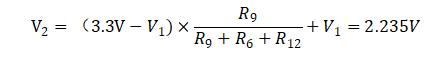
where V2 is the voltage on the non-inverting input pin of the comparator.
(1) Assuming the initial output level of the comparator is low:
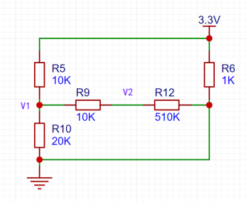
Figure 9 Initial low level Schmitt trigger
When the initial level of the comparator is low, the original circuit diagram can be simplified to Figure 8. The voltage V+ of the non-inverting input pin of the voltage comparator is the voltage division across the 10kΩ resistor, so:
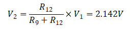
where V2 is the voltage on the non-inverting input pin of the comparator.
Therefore, when the input at the inverting input terminal is greater than 2.235V, the comparator will output a low level, and when it drops to 2.142V, the comparator will output a high level.


 京公网安备 11010802033920号

 SMDA03C


