The design is based on [@zhqsoft's open-source project](https://oshwhub.com/zhqsoft/CH9329-M01). For a detailed description, please click on the project link; I won't repeat it here.
Based on the design, I replaced the CH340C with the smaller CH340X, modified the schematic according to my own style, and made a slight negative optimization to the wiring.
Hardware testing has passed; the Device Manager recognizes both the HID device and the serial port, and the 9329 tool correctly identifies the tool (approximately, see the images:
![Serial Port]

![HID]
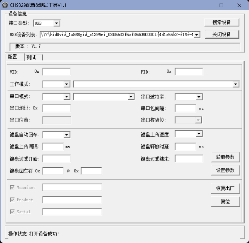
). Honestly, I'm not very good at using this stuff; it's like a kid playing around with unnecessary components. You don't necessarily need resistors from the same brand as those in the project file; the size just needs to be the same (I used them because I bought too many last time). I've already included the necessary tools; just refer to the project for usage instructions. Don't ask me; I'm not very good at it either.
Below are two pictures of the actual device.
![Top]

![Bottom]

CH9329 Data Collection.rar
PDF_Mouse and Keyboard Simulator Based on CH9329.zip
Altium_CH9329-based mouse and keyboard emulator.zip
PADS_CH9329-based mouse and keyboard emulator.zip
BOM_Mouse and Keyboard Simulator Based on CH9329.xlsx
95561
ADC Sampling Module with Signal Conditioning Based on AD9288_2022-11-26_09-47-01
The AD9288 is an ADC sampling module with signal conditioning that supports dual-channel DC/AC coupling and x1 and x25 attenuation levels. Depending on the chip model purchased, it offers 8-bit 40 MSPS, 80 MSPS, and 100 MSPS sampling rate options.
The AD9288 is a signal-conditioned ADC sampling module that supports dual-channel DC/AC coupling and attenuation levels of
x1 and x25. Depending on the chip model purchased, it offers 8-bit sampling rates of 40 MSPS, 80 MSPS, and 100 MSPS. Each channel has a 475MHz analog bandwidth and a 1Vp-p analog input range. A limiting module is included to prevent overvoltage damage. A gas discharge tube is used for lightning protection, and a differential operational amplifier amplifies and processes the signal. Zero-crossing detection is achieved using a comparator. Isolation is achieved using an insertion follower, which not only cuts off the ground loop but also blocks high-voltage surges and high common-mode voltages.
In practical voltage conversion,
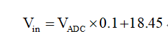
the AD9288 is an 8-bit ADC with a bias voltage of 1.25V. The measurement range is ±0.512V relative to the bias voltage, with an absolute range of 0.738~1.762V. When using the x25 setting for the ADC front-end input, the following formula can be derived based on the above information:

where $V{in}$ is the raw data input of the ADC module, $V{ADC_out}$ is the 8-bit data output of the ADC, is the minimum voltage sampling value of the ADC, is the maximum sampling voltage of the ADC, and 0.738 is the absolute minimum voltage value within the ADC sampling range. The overall calculation process involves the signal first being attenuated to 1/25 by the ADC conditioning circuit. At this point, the analog data read by the ADC is equal to the normalized data from the ADC digital terminal multiplied by the ADC sampling range, plus the bias voltage.
In summary, the simplified calculation formula when using the x25 setting is as follows:
Digital output, level, and power supply
digital terminals use a parallel pin header output. Note that this module does not have a built-in clock and requires an external clock signal.
The pin header signal definitions are as follows:
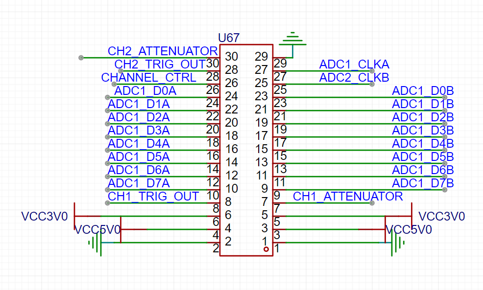
pins 27 and 25 are clock signal inputs; in addition to the single-throw switch function, pins 26, 28, and 30 can also be used for signal control. Pins 10-24 are the data output of channel 1, and pins 9-23 are the data output of channel 2. All signal levels are 3.3V. The power supply input can be directly input at pins 5 and 6 with 3.3V, or at pins 3 and 4 with 5V.
PDF_ADC Sampling Module with Signal Conditioning Based on AD9288_09-47-01.zip
Altium_AD9288-based ADC sampling module with signal conditioning_09-47-01.zip
PADS_ADC Sampling Module with Signal Conditioning Based on AD9288_09-47-01.zip
BOM_ADC Sampling Module with Signal Conditioning Based on AD9288_2022-11-26_09-47-01.xlsx
95562
Hisilicon H105 WiFi Adapter Card (SDIO to TF)
Hisilicon H105 WiFi Adapter Card (SDIO to TF)
The Hisilicon H105 WiFi adapter card (SDIO to TF card)
requires 5V for FEM and 3.4V for VDD.
Power-on control is entirely managed by SD_VDD.
That's it.
PDF_HiSilicon H105 WiFi Adapter Card (SDIO to TF).zip
Altium_HiSilicon H105 WiFi Adapter Card (SDIO to TF).zip
PADS_HiSilicon H105 WiFi Adapter Card (SDIO to TF).zip
BOM_HiSilicon H105 WiFi Adapter Card (SDIO to TF).xlsx
95563
LM2596S_ADJ Dual-channel Adjustable Voltage Regulator
The slider needs to be adjusted to the appropriate resistance value.
Engineering Features: 12V battery input, voltage conversion achieved through the LM2596-S ADJ voltage regulator circuit;
regulates the input voltage from 0-12V.
Note: The variable resistor must be adjusted to a suitable value for voltage regulation; the variable resistor value is 1M ohms, and the resistor and capacitor packages are 0805.
PDF_LM2596S_ADJ Dual-channel Adjustable Voltage Regulator.zip
Altium_LM2596S_ADJ Dual-channel Adjustable Voltage Regulator.zip
PADS_LM2596S_ADJ Dual-channel Adjustable Voltage Regulator.zip
BOM_LM2596S_ADJ Dual-channel Adjustable Voltage Regulator.xlsx
95564
AD8367_amplifier_2023-07-05_10-05-36
Based on the AD8367 variable gain amplifier, it supports VCA and AGC modes and allows manual adjustment of the amplification factor. The gain range is −2.5 dB to +42.5 dB, the frequency range is LF to 500 MHz, and the input impedance is 200 Ω.
Based on the AD8367 variable gain amplifier, it supports VCA and AGC modes and allows manual adjustment of the amplification factor. The gain range is −2.5 dB to +42.5 dB, the frequency range is LF to 500 MHz, and the input impedance is 200 Ω.
PDF_AD8367_amplifier_10-05-36.zip
Altium_AD8367_amplifier_10-05-36.zip
PADS_AD8367_amplifier_10-05-36.zip
BOM_AD8367_amplifier_2023-07-05_10-05-36.xlsx
95568
ZYNQ7-Pi
ZYNQ7-Pi, compatible with XC7Z010/XC7Z020/XC7Z007S/XC7Z014S-CLG400
ZYNQ7-Pi, compatible with XC7Z010/XC7Z020/XC7Z007S/XC7Z014S-CLG400
four-layer boards, free to use. Features integrated USB 2.0 and Gigabit Ethernet on the PS side, and an HDMI port on the PL side.
Modified from zynq_mini_pi_S - JLCPCB's EDA open-source hardware platform (oshwhub.com)
has modified the power supply scheme, changing the long-standing situation where players struggle with soldering DC-DC converters. All ports
except USB and HDMI have been tested. My skill level is limited and I don't know how to handle HDMI. I bought the wrong resistor for USB; I'll test it when the new one arrives.
The file is PCB_zynq_mini_1. For the PCB mounting impedance, choose 3313 (otherwise, PS will definitely crash – a painful lesson learned).
Debugging points
: 1. After soldering the ZYNQ, if you find that JTAG has no resistance except for TCLK, please replace it with a new board. The reason seems to be related to solder mask detachment under the BGA; in any case, it's definitely a ZYNQ cold solder joint. However, many times you can't solder it well even after 10 attempts, but replacing the board might solve the problem.
2. All down DIP switches are for SD boot, all up are for JTAG boot, 1 up and 2 down are for QSPI Flash boot, 1 down and 2 up are ineffective.
3. JTAG is powered by a standard 14-pin FPGA. The JTAG interface is a simplified version, so it is compatible with EBAZ4x0x, but may conflict with the 40P header.
4. 3.3V is provided by AMS1117, and after the switch, the current is limited to 500mA. If it exceeds this, it will directly protect the device.
5. I used 7020. You can try the rest yourself.
6. Opening the stencil can make things much easier, but it is also possible to use a soldering iron to tin and then blow it with a hot air gun/hot plate.
Known issues:
The USBCP_EN signal does not have a pull-down resistor.
Regarding
the latest version of Board1_2, a pull-down resistor has been added, and the GND copper in the BGA has been removed (to solve the problem of easy cold solder joints). It has not yet been tested.
About the author:
AbuzzHarbor9999 is my Xbox player code name. When I log in to Minecraft Bedrock Edition, I am randomly generated as
a high school student (actually a vocational school student preparing for the college entrance examination. Except for not being able to bring a mobile phone to school, everything is quite easy, but unfortunately, I am extremely slow at doing homework). I
have been into electronics for more than a year and am familiar with fixed-wing flight controllers, Linux, and Arduino. I've been interested in Qt and
flown model airplanes a few times, but my skill level is extremely poor.
I've only dabbled in FPGA, and can only turn on some LEDs (which is why I don't know how to adjust HDMI, and another reason is that my Vivado and Petalinux versions are too high).
I've attached the LED code at the end (it's actually in the attachment).

led.v
PDF_ZYNQ7-Pi.zip
Altium_ZYNQ7-Pi.zip
PADS_ZYNQ7-Pi.zip
BOM_ZYNQ7-Pi.xlsx
95570
Numeric keypad (RP2040, screen, knob)
The project uses the Raspberry Pi pico development board, compatible with development boards from YD and Wuming Technology. It adopts the qmk solution.
The project uses the Raspberry Pi pico development board, compatible with development boards from YD and Wuming Technology. It adopts the QMK solution.
There's a problem with the PCB: a fly-wire needs to be connected from the development board's 5V to an RGB LED's VDD for the LED to light up.
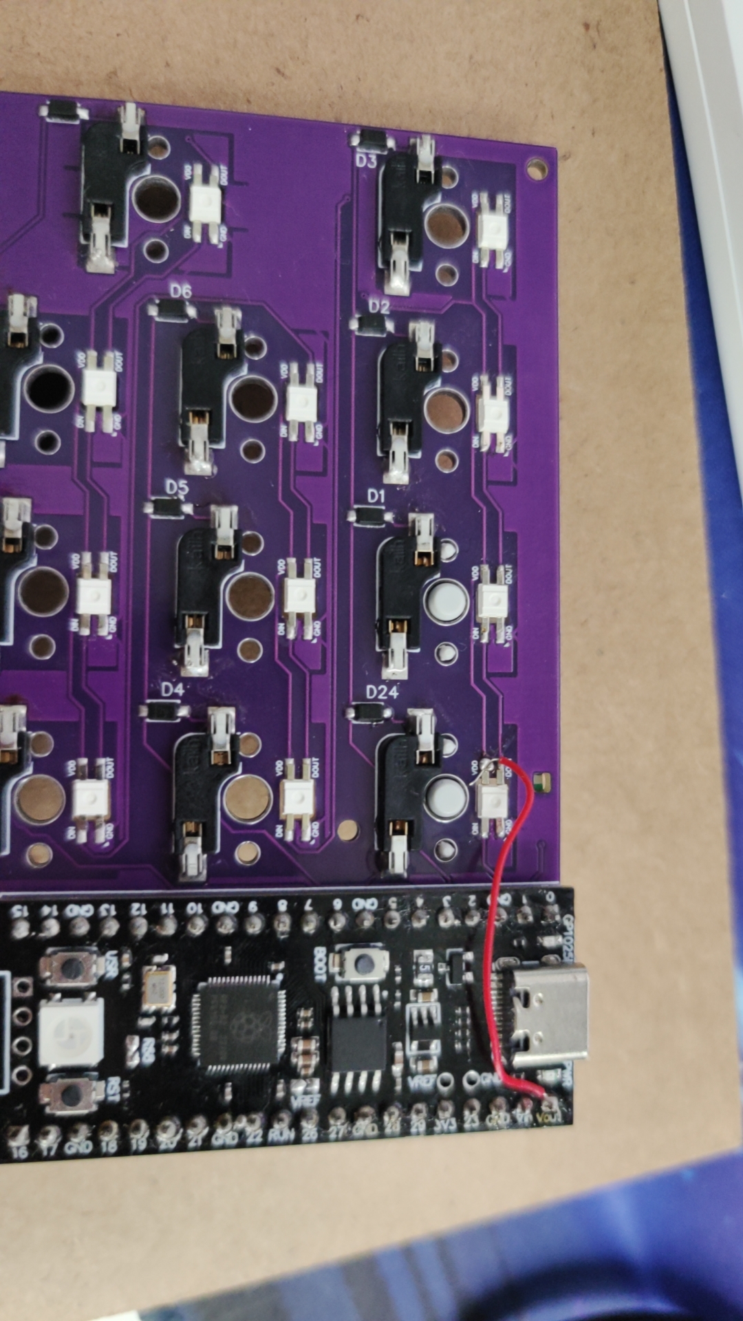
The attached .uf2 file is the firmware; simply drag and drop it into the Raspberry Pi's disk to burn it. This is the simplest burning method, which is why I chose the Raspberry Pi.
The other two components are the casing and the positioning board.
The screen requires a 0.91mm IIC screen, costing approximately 8 yuan. The screen needs to be separated from the board using alcohol or board cleaner before it can be inserted. (A modeling error occurred.) The screen board is placed under the positioning board and connected to the IIC interface with a fly-wire.

rpnumpad2_default.uf2
new3 v16.stl
Hull standalone v14.stl
PDF_Number Keyboard (rp2040, Screen, Knobs).zip
Altium numeric keypad (rp2040, screen, knobs).zip
PADS Numeric Keypad (rp2040, Screen, Knob).zip
BOM_Numeric Keypad (RP2040, Screen, Knob).xlsx
95572
Pull-up potentiometer adapter board
Pull-up potentiometer adapter board
This functional description
applies to most pull-up potentiometers and microphones.
Currently verified to be compatible with Epiphone microphones with correct wiring.
Manufacturing notes:
Board thickness 1.0mm; note that half-hole manufacturing is not permitted.
Open Source Notice:
This project is licensed under the CC BY-NC 3.0 open source license; please see the link for details.
You are free to: Share — reproduce, distribute, adapt, modify, transform, or create based on this work
in any form or medium. As long as you comply with the terms of the license agreement, the licensor cannot revoke these rights. However, you must comply with the following conditions: Attribution — You must give appropriate attribution, provide a link to this license agreement, and indicate whether modifications were made (to the original work). You may use any reasonable means of attribution, but you must not in any way imply that the licensor endorses you or your use. Non-Commercial Use — You may not use this work for commercial purposes. No Additional Restrictions — You may not use legal terms or technical measures to restrict others from doing what is permitted under this license agreement. Disclaimer: You are not obliged to comply with the license agreement due to elements of the work in the public domain, or your use is permitted by applicable exceptions or limitations. No warranties are provided. The license agreement may not grant all the necessary permissions for your intended use. For example, other rights such as image rights, privacy rights, or moral rights may restrict how you use the work.
PDF_Pull-up Potentiometer Adapter Board.zip
Altium Pull-Up Potentiometer Adapter Board.zip
PADS Pull-up Potentiometer Adapter Board.zip
BOM_Pull-up Potentiometer Adapter Board.xlsx
95573
electronic


 京公网安备 11010802033920号

 HCHP1005M4874DNT


