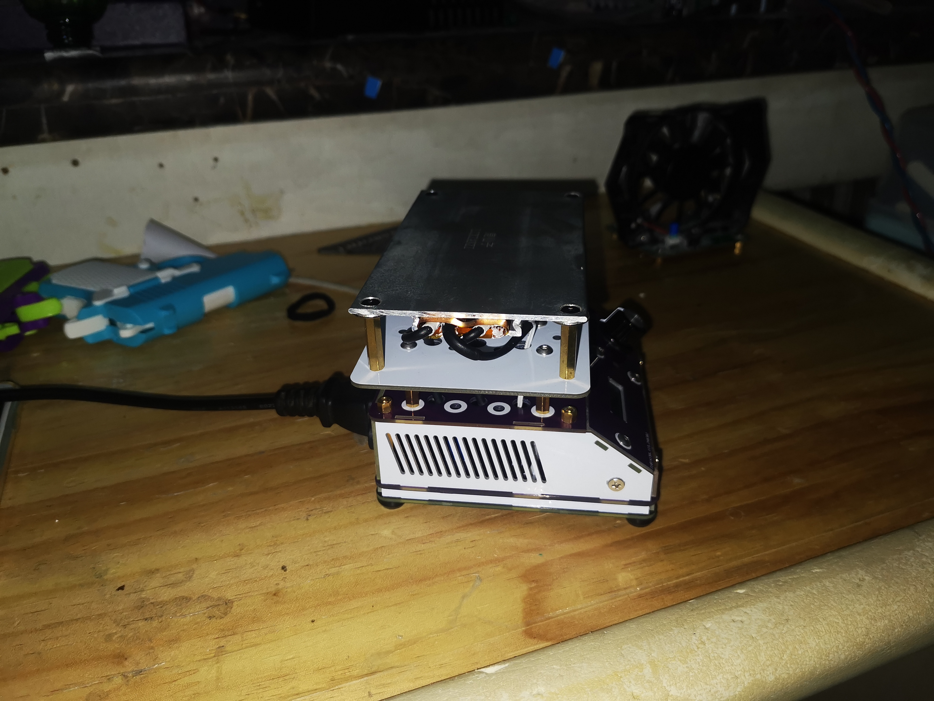
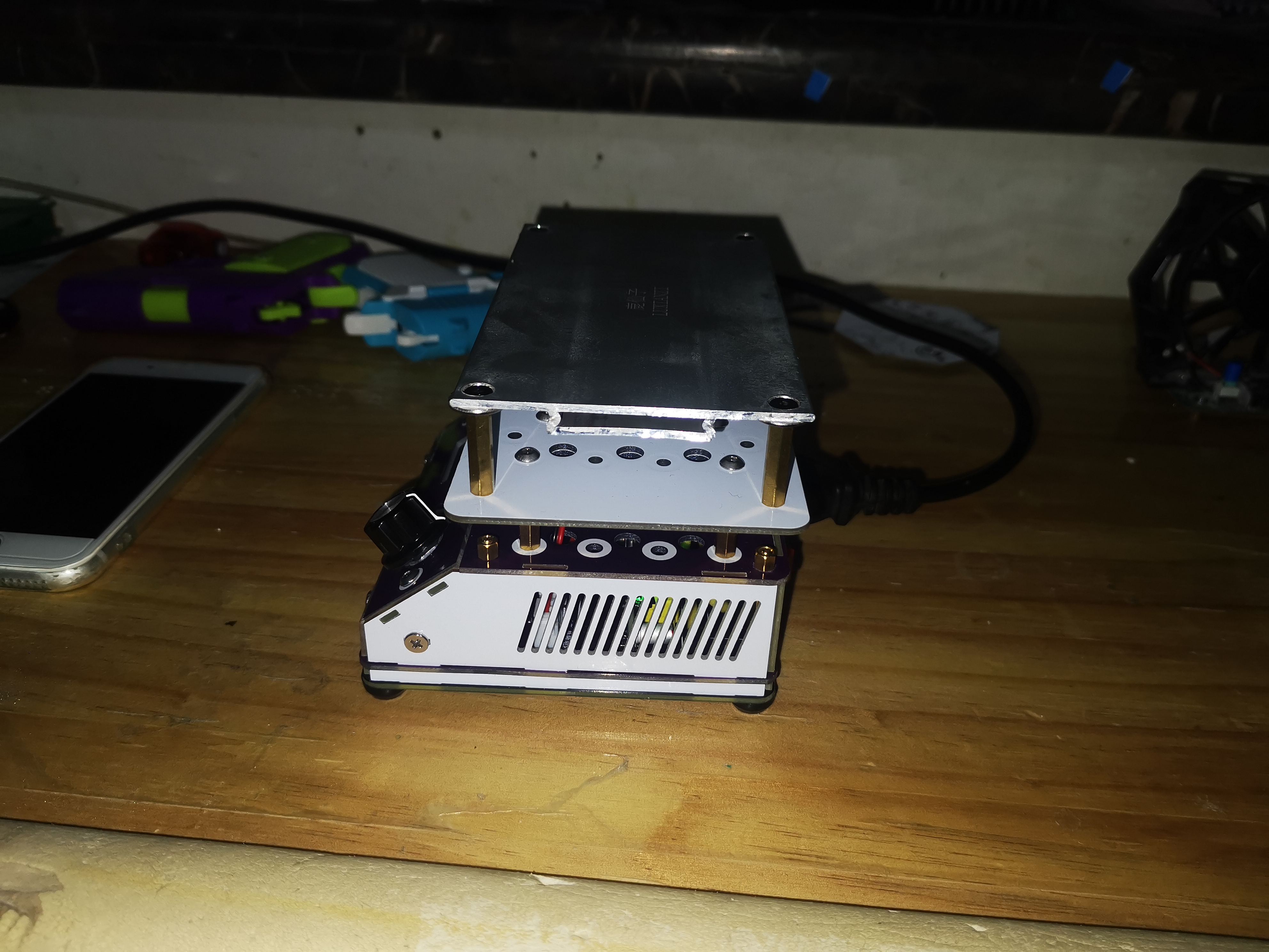
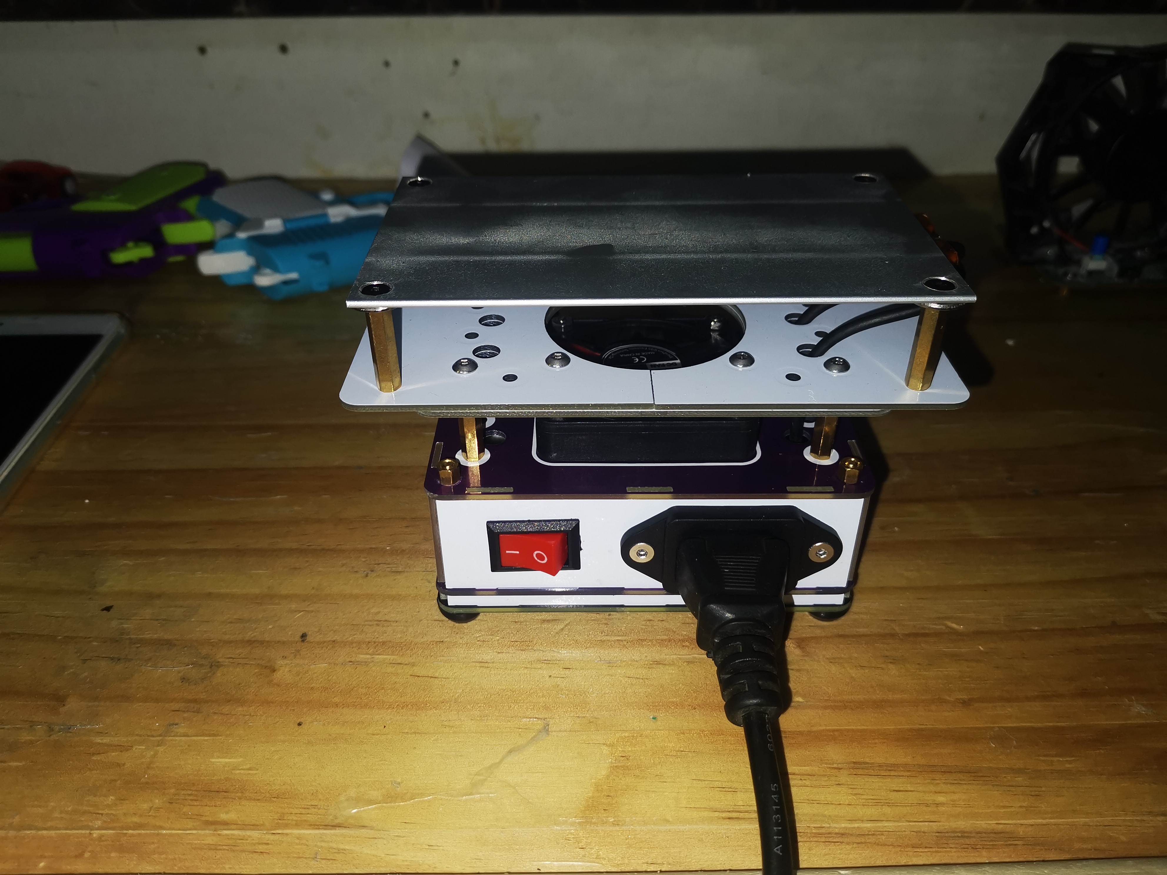
The principle is based on https://oshwhub.com/dhx233/pcb-heng-wen-jia-re-taipcb, and has undergone multiple sampling and optimization processes (self-cutting is required). Several M3 copper pillar screws are needed.


PDF_Heating Table Mass Production Plan (Complete PCB Version).zip
Altium_Heating Platform Mass Production Plan (Complete PCB Version).zip
PADS_Heating Stage Mass Production Plan (Complete PCB Version).zip
BOM_Heating Table Mass Production Plan (Complete PCB Version).xlsx
95601
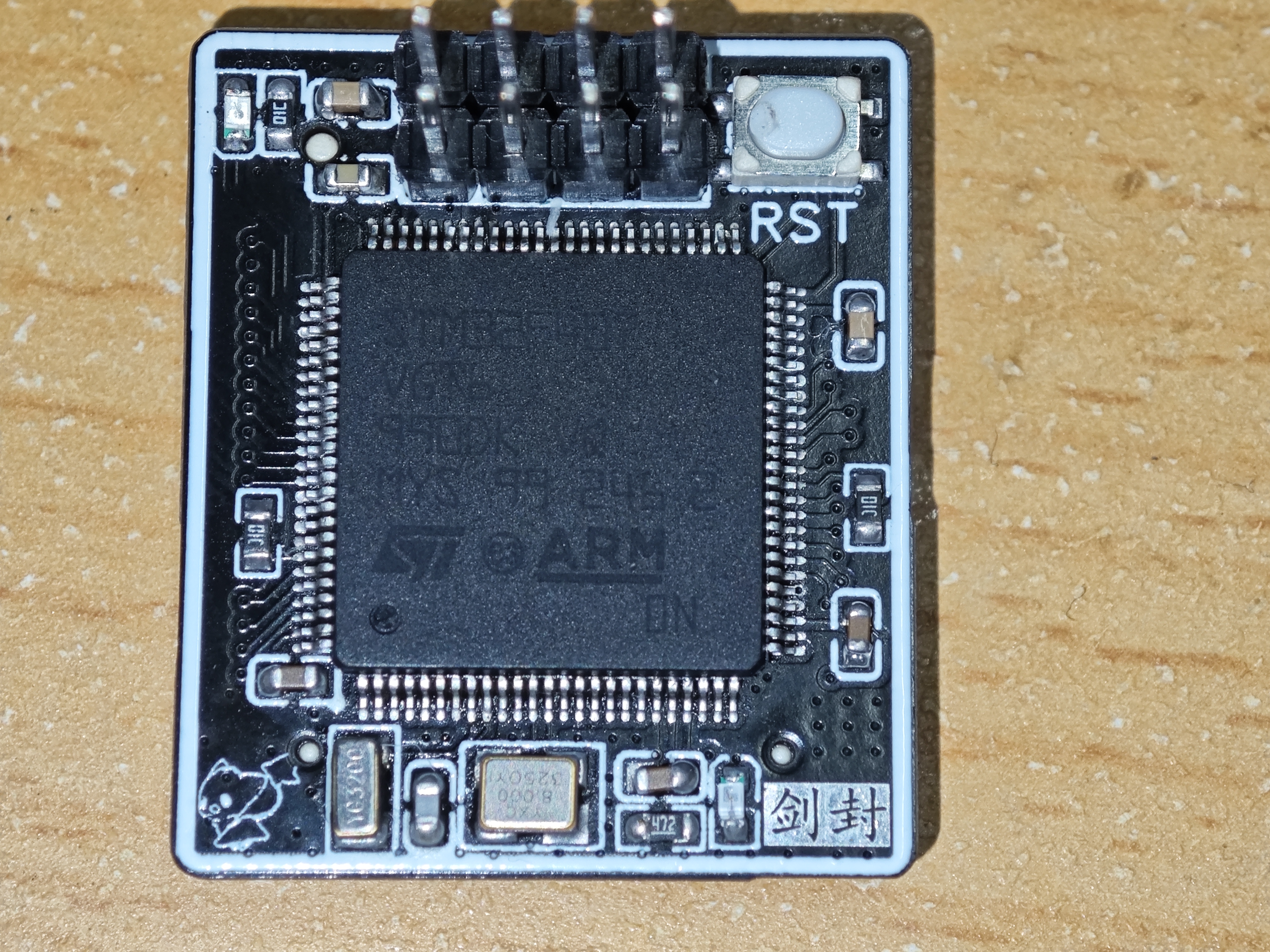
STM32F407VGT6 Minimum System Board
This is the smallest system board for the STM32F407VGT6, using a 0.8mm BTB connector for connections, with all pins brought out.
Project Name: STM32F407VGT6 Minimum System Board
Project Description: This is a minimum system board based on the STM32F407VGT6 microcontroller, using 0.8mm BTB connectors for connectivity. The system board features a compact design, exposing all pins of the STM32F407VGT6 microcontroller, making it easy to integrate into various applications. It employs a 2-layer board design. Only 5 resistors and capacitors are present on the back of the connector, making soldering very convenient.

Key Features:
Uses the STM32F407VGT6 microcontroller, offering high performance and rich peripheral functionality.
Uses 0.8mm BTB connectors for easy connection and integration with other devices.
Compact size design suitable for space-constrained applications.
All pins are exposed, providing flexible expansion and customization capabilities.
Project Goals:
To design and release open-source STM32F407VGT6 minimum system board schematics and PCB layouts.
To encourage participation and contributions from the open-source community to further improve and refine this project.
Important Notes:
The 5V pin of this board cannot power the microcontroller. A custom-designed baseboard is required to step down the voltage to 3.3V to power the microcontroller.
Users assume all risks and responsibilities arising from the use of this system board.
PDF_STM32F407VGT6 Minimal System Board.zip
Altium_STM32F407VGT6 Minimal System Board.zip
PADS_STM32F407VGT6 Minimal System Board.zip
BOM_STM32F407VGT6 Minimum System Board.xlsx
95603
air001 Mini Development Board
The AIR001 mini development board has been tested and verified. It supports microUSB and can be directly plugged into the DAPlink motherboard.
The mini development board developed for HeZhou air001 has been tested and verified.
Feel free to discuss any issues in the comments section
. Important notes:
The programming interface only requires soldering 7 pins; you can directly cut an 8-pin header and solder it on (refer to the cover).
Differences from the official development board:
A bunch of interfaces have been removed (such as BOOT, RST, etc., controlled directly by buttons, but generally not needed except for programming).
To simplify component soldering, the automatic download circuit has been removed.
The original 3 LEDs have been changed to 2 (one lights up upon power-on, the other is controlled by PB_0, lighting up when pulled low).
This is a 4-layer board
// very small, probably no smaller…
The IIC interface has been separated, allowing direct insertion into an IIC screen (the official version also has a separate interface, but that needs to be soldered in reverse…).
The header has been changed to a female header for easier wiring (you can also solder headers, but note the gap between the two rows of headers, preventing insertion into the breadboard).
5V and GND are separately brought out for easier power supply
. TYPE-C has been changed to microB for easier soldering.
2024.03 Update:
Now HeZhou charges shipping fees, the AIR001's cost-effectiveness is practically nonexistent, and I no longer recommend purchasing it. [RIP Luat]
PDF_air001 Mini Development Board.zip
Altium_air001 Mini Development Board.zip
PADS_air001 Mini Development Board.zip
BOM_air001 Mini Development Board.xlsx
95605
PD decoy (verified)
PD decoy based on CH224K chip design
The Type-C interface is for input. This module requires a PD-compatible charger or power bank to power it. The output voltage is adjusted via a DIP switch, with only one switch on at a time. It can output 5V, 9V, 12V, 15V, and 20V. See the PCB silkscreen for specific voltages and corresponding switches. The output is led out via pin headers or wires and can power other modules or circuit boards (of course, this can be directly integrated onto other PCBs).
PDF_PD Deception (Verified).zip
Altium_PD Deception (Verified).zip
PADS_PD Deceptive Tool (Verified).zip
BOM_PD Deception (Verified).xlsx
95607
Cyber Anti-Bug Charm
The main control uses the ASR Pro Tianwen microcontroller, which is simple to develop with and has official example code available for modification.
The Cyber Anti-Bug Charm is a multi-functional soldering station assistant that integrates voice control, RGB lighting, microphone, temperature, humidity and time display, and LED fill light,
while also providing anti-bug functionality.
6. Voice-controlled WS2812 colored lights.hd
PDF_Cyber Anti-BUG Charm.zip
Altium_Cyber Anti-BUG Charm.zip
PADS_Cyber Anti-BUG Charm.zip
BOM_Cyber Anti-BUG Charm.xlsx
95608
ESP8266 2.4G WiFi Killer_2024-02-29_07-25-02
WiFi Killer based on ESP8266
WiFi detection, powered by a 3.7V lithium battery.
WeChat_20240323195924.mp4
PDF_ESP8266 2.4G WiFi Killer_07-25-02.zip
Altium_ESP8266 2.4G WiFi Killer_07-25-02.zip
PADS_ESP8266 2.4G WiFi Killer_07-25-02.zip
BOM_ESP8266 2.4G WiFi Killer_2024-02-29_07-25-02.xlsx
95609
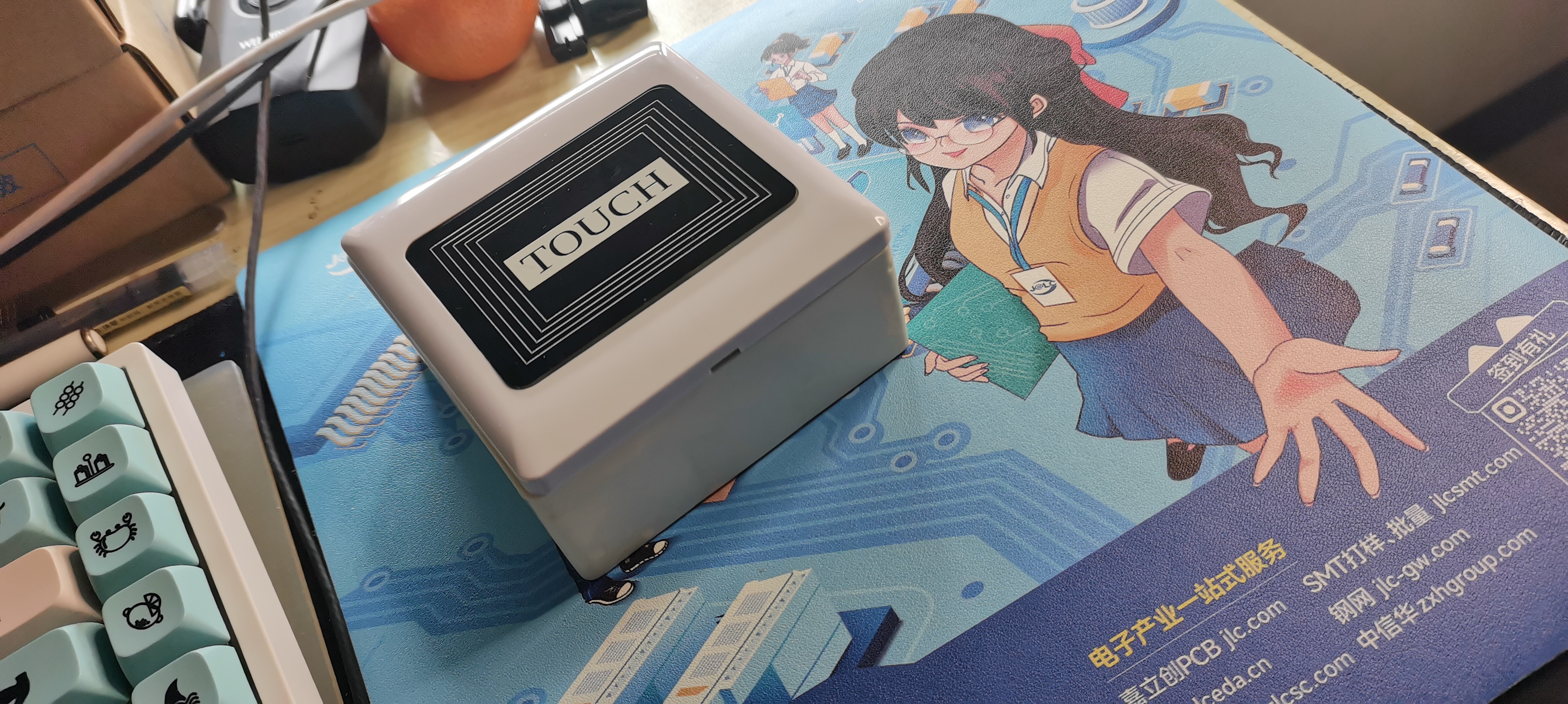
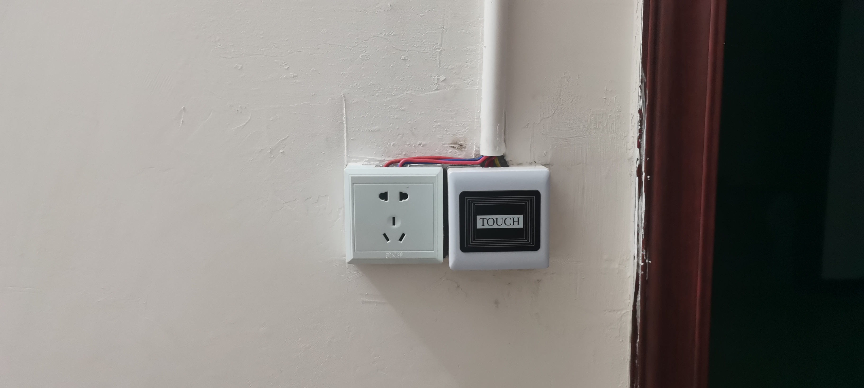
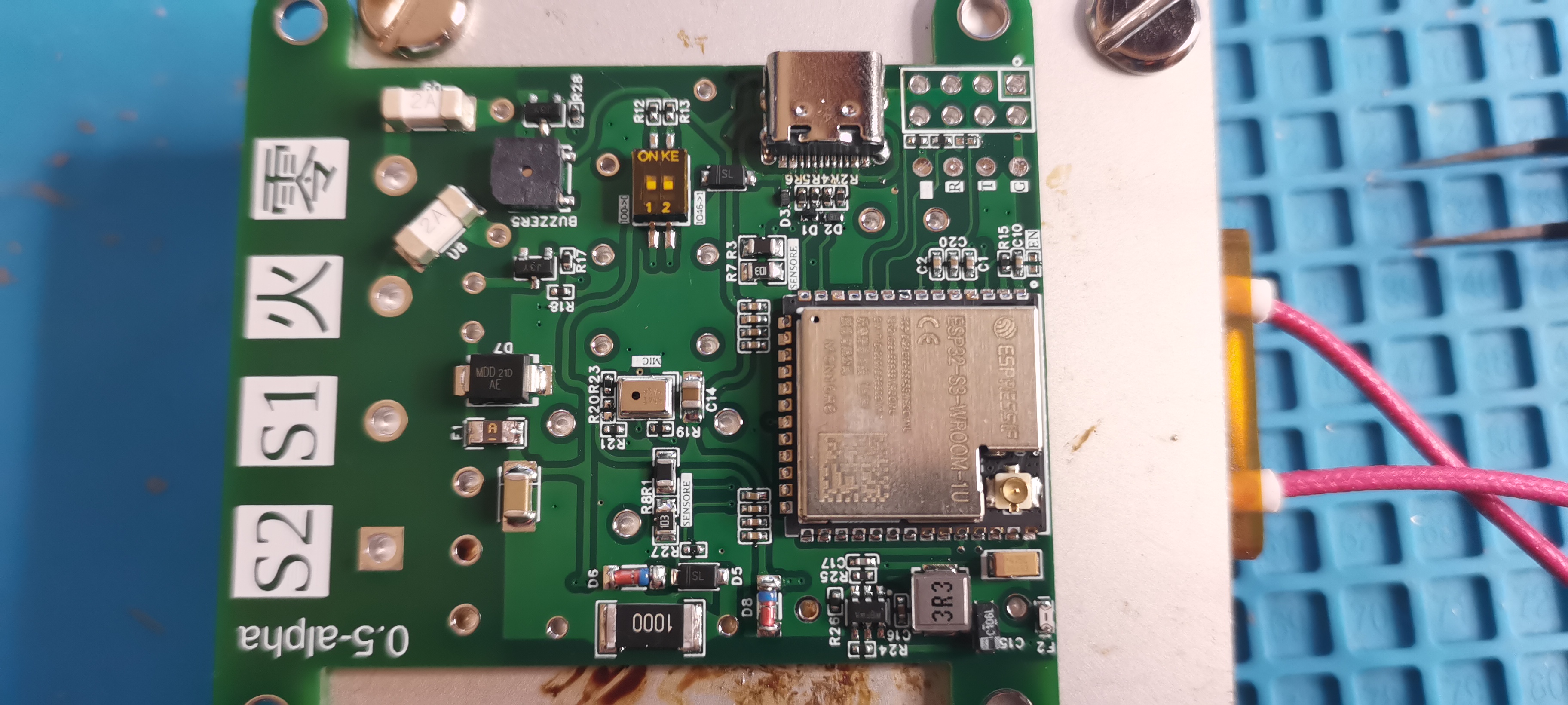
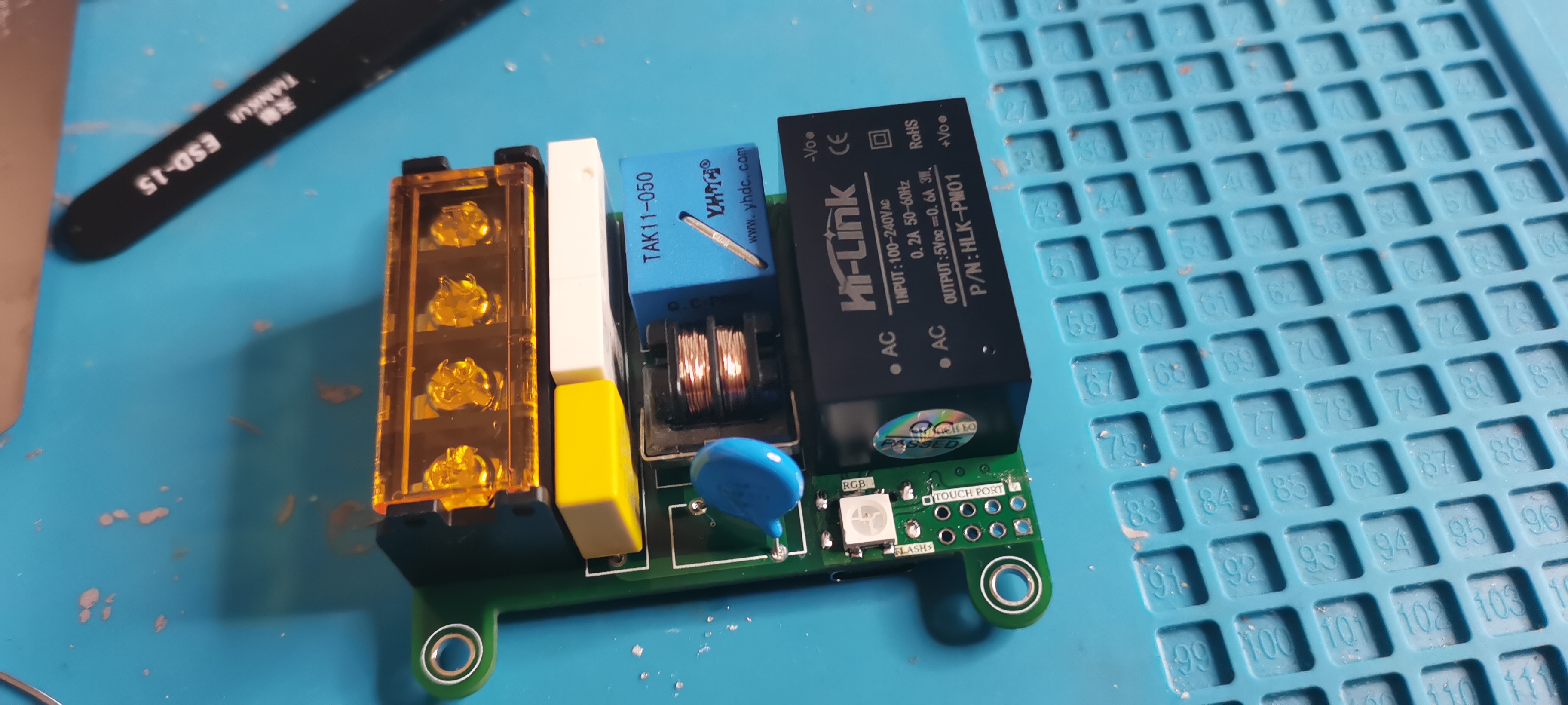
Graduation Project: "Type 86" Internet of Things Switch
An IoT switch supporting QQ, web, touch, and voice control, based on ESP-IDF, Drogon, QtMqtt, and Angular – this is my graduation project.
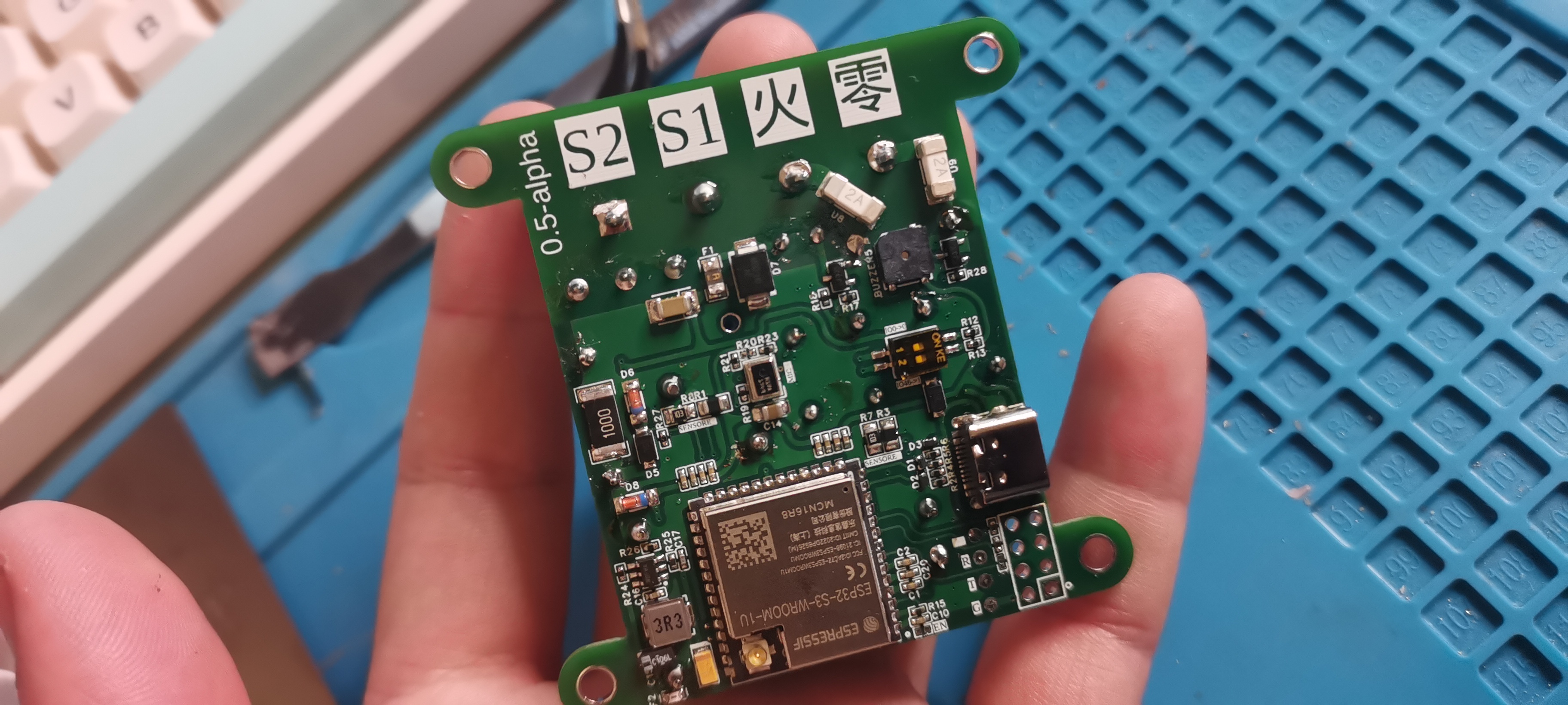
The "Type 86" IoT switch is a finished product demonstration project
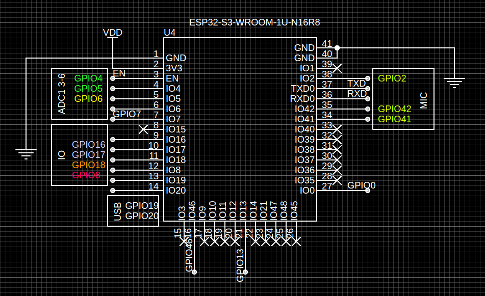
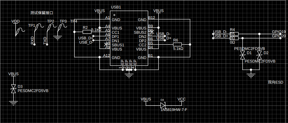
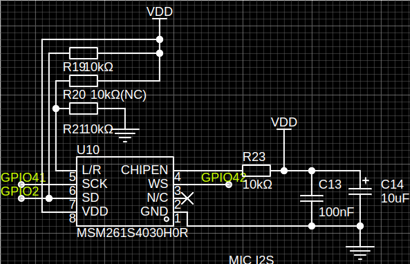
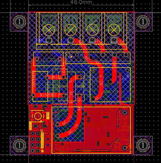
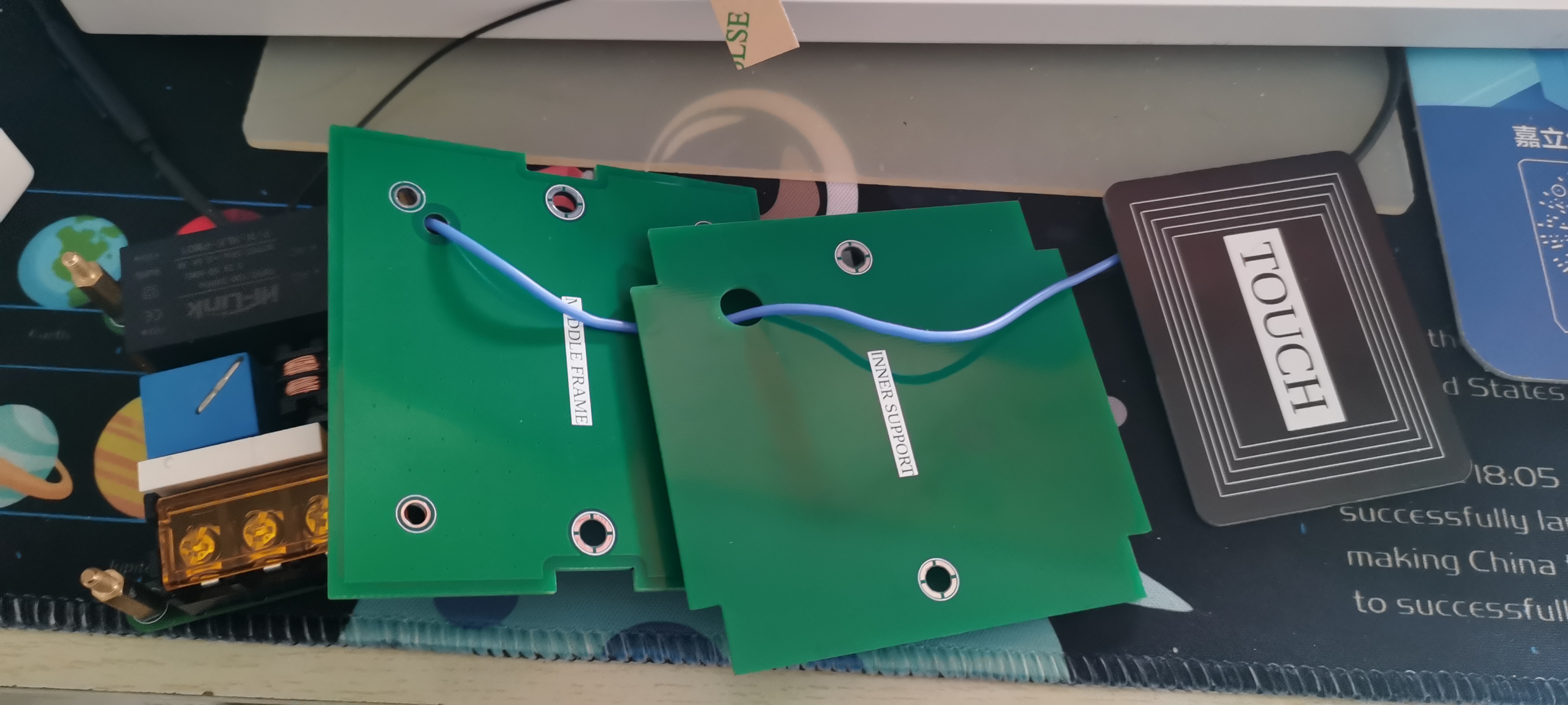
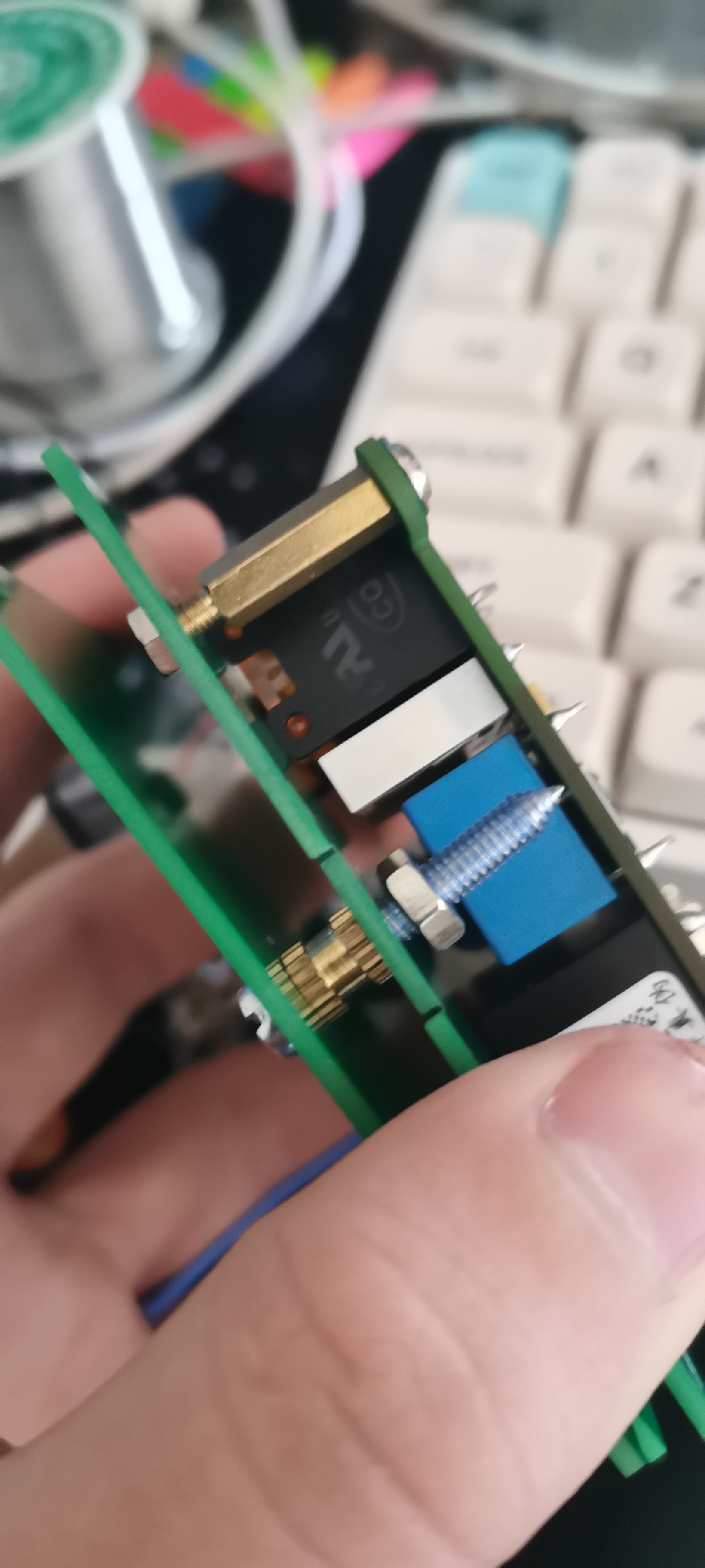
supporting QQ, WEB, touch, and voice control. The project consists of: switch hardware (IOTSwitch firmware based on ESP-IDF) , IoT Server (host computer based on Drogon, QtMqtt, Angular, and GoCqHttp) , switch hardware (back PCB, front PCB schematic design) , ESP32-S3 module, AC-DC isolated power supply module, DC-DC synchronous buck circuit , single-pole double-throw relay, USB-DEBUG circuit, current transformer output detection, I2S microphone circuit, NTC temperature sensor, touch interface, and BOOT. Optionally , the ESP32S3 module selected is the ESP32-S3-WROOM-1U-N16R8. The main control antenna of the ESP32-S3-WROOM-1U-N16R8 module uses an external interface and can be mounted on the back of the 86-type box. The AC-DC power supply uses a Hailingke HLK-PM01 as the isolated power supply, providing 220VAC->5VDC to power the relay. The DC-DC power supply uses a SY8120B1ABC synchronous step-down transformer, providing 3V AC from 5VAC to 3V AC to power the main control unit. A 4.7uH inductor is used. The 0420 package relay uses Hongfa's HF41F/5-ZS as the output control relay. The USB-DEBUG circuit omits a USB-TO-SERIAL circuit for DEBUG and program download output detection. This circuit is currently unavailable. A TAK11 current transformer is used due to PCB space constraints. Special thanks to Beijing Yaohua Dechang Electronics for shipping even when I ordered one or two; they were very helpful during my inquiry. The microphone uses an MSM261S4030H0R, referencing the ESP32-S3-EYE development board. Temperature sensing uses two thermistors to divide the voltage and measure the temperature, achieving high-temperature alarm touch detection . The ESP32-S3 uses GPIO7 as the default touch IO; the software allows setting the trigger threshold and protection time. The BOOT Option documentation is very detailed and will not be repeated here. // TODO Add Document link Other WS2812 MLT-5020 PCB design: The PCB uses a four-layer board: layer 1 for high voltage, layer 2 for internal power, and layers 3 and 4 for signals. Four-layer layout, one-layer layout, IO function overview. Hardware V0.5 Pin Target Announce P4 NTC_R3 ADC1_CH3 P5 CURR_SEN ADC1_CH4 P6 NTC_R1 ADC1_CH5 P7 TOUCH NAN P8 WS2812 NAN P13 BUZZER NAN P16 OUT_PORT NAN P17 OUT_PORT NAN P18 RELAY HIGH TO OPEN P2 MIC_SD NAN P41 MIC_SCK NAN P42 MIC_WS NAN IOTSwitch Function Overview MQTT Control Touchpad Control Voice Control Project Dependencies Component core support esp-idf >=5.0 espressif/esp-sr espressif/mdns espressif/esp-idf-cxx espressif/esp_mqtt_cxx espressif/led_strip bblanchon/arduinojson diam2023/ok_wifi If using espressif/esp-tflite-micro, refer to sheila_wake_up for details. See IOTSwitch/main/idf_component.yml for network configuration instructions. Refer to the OkWifi documentation (under development). MQTT instructions: Publish topic message format: devices/{SN}/status DeviceStatus {"status":bool} devices/{SN}/config DeviceConfig {"config...":"value..."}


Subscribe
topic
message
format
devices/{SN}/setting
DeviceSetting
{"setting...": "value..."}
devices/{SN}/action
DeviceAction
{"action": "..."}
Action List
action
value
sub data
announce
set status
setStatus
{"status": bool}
NON
system restart
restart
NON
NON
get status
getStatus
NON
publish status
get config
getConfig
NON
publish config
Configuration file list
referenceIOTSwitch/config/setting.json
{
"configVersion": "0.0.1",
"beepMute": false,
"voltageSensor": {
"outputThreshold": 50,
"temperatureThreshold": 2000
},
"touchpad": {
"notifyThreshold": 40000,
"touchLimitThreshold": 250
},
"wifi": {
"ssid": "×××",
"pwd": "×××"
},
"mqtt": {
"host": "mqtt://192.168.0.188",
"port": 1883
}
}
Configuration file description:
beepMute: Whether the buzzer is muted (ignore this option for alarms)
outputThreshold: Output detection threshold
temperatureThreshold: Temperature detection alarm threshold
notifyThreshold: Touchpad trigger threshold
touchLimitThreshold: Touch protection threshold
Wi-Fi: Network configuration data; if configured in advance, network configuration is not required.
MQTT Broker IP and PORT settings: Must be configured in advance.
Main control module replacement instructions
refer to partitions.csv. Select capacity
# Name, Type, SubType, Offset, Size, Flags
# Note: if you have increased the bootloader size, make sure to update the offsets to avoid overlap
nvs, data, nvs, 0x009000, 24k,
phy_init, data, phy, 0x00f000, 4k,
factory, app, factory, 0x010000, 4032k,
model, data, spiffs, 0x400000, 4096k,
config, data, spiffs, 0x800000, 512k,
fr, data, , 0x880000, 128k,
Deployment
# Clone project
git clone https://github.com/Diam2023/IOTSwitch IOTSwitch_local
cd IOTSwitch_local
# Compile
idf.py build
# Write to and monitor
idf.py flash monitor
Notes
If the serial port is not found or unstable during the first write, you can short-circuit IO0 to power on.
IOTServer
https://github.com/Diam2023/IOTServer
Description
Supports QQ and WEB controlled host computer, responsible for message listening and push (pushing to users, pushing to devices)
Uses MySQL to store account and device information, and Redis login cache
Configuration file: config/config.yaml
Docker configuration file: /*
Before deployment, you need to configure the CQ reverse WebSocket address under Docker. If you don't need QQ, you don't need
to depend on
Drogon. */A C++14/17/20 based HTTP web application framework running on Linux/macOS/Unix/Windows.
QtMqtt,
QtCore, and
QtWebSocket are recommended
for deployment
. Docker is best used for deployment; if not, try installing on an Arch-based system, as Debian is cumbersome.
Docker one-click deployment
git clone -b docker https://github.com/Diam2023/IOTServer
# Or switch to
cd ./IOTServer/docker
docker compose run *
# use -d if need
# docker compose stop
Local deployment
must rely on
MySQL (MariaDB)
Redis
yaml-cpp
Drogon
Yaml-Cpp
Arch
yay -S yaml-cpp
Debian
sudo apt install libyaml-cpp-dev
Install QtMqtt
https://github.com/KurtPattyn/QtMqtt
Arch
yay -S qt5-mqtt
Debian
git clone -b 5.12.3 git://code.qt.io/qt/qtmqtt.git qtmqtt
cd qtmqtt
mkdir build
cd build
qmake ..
make
sudo make install
###### Install Drogon
> https://github.com/drogonframework/drogon/wiki/ENG-02-Installation
* Arch
```shell
yay -S drogon
Debian
git clone https://github.com/drogonframework/drogon
cd drogon
./build
Build IOTServer
git clone https://github.com/Diam2023/IOTServer
cd IOTServer
# build angular
cd site
yarn install
yarn build
cd ..
# build IOTServer
./build # Build
cd build
# Run
./IOTServer
API Reference
QQ Control
Help
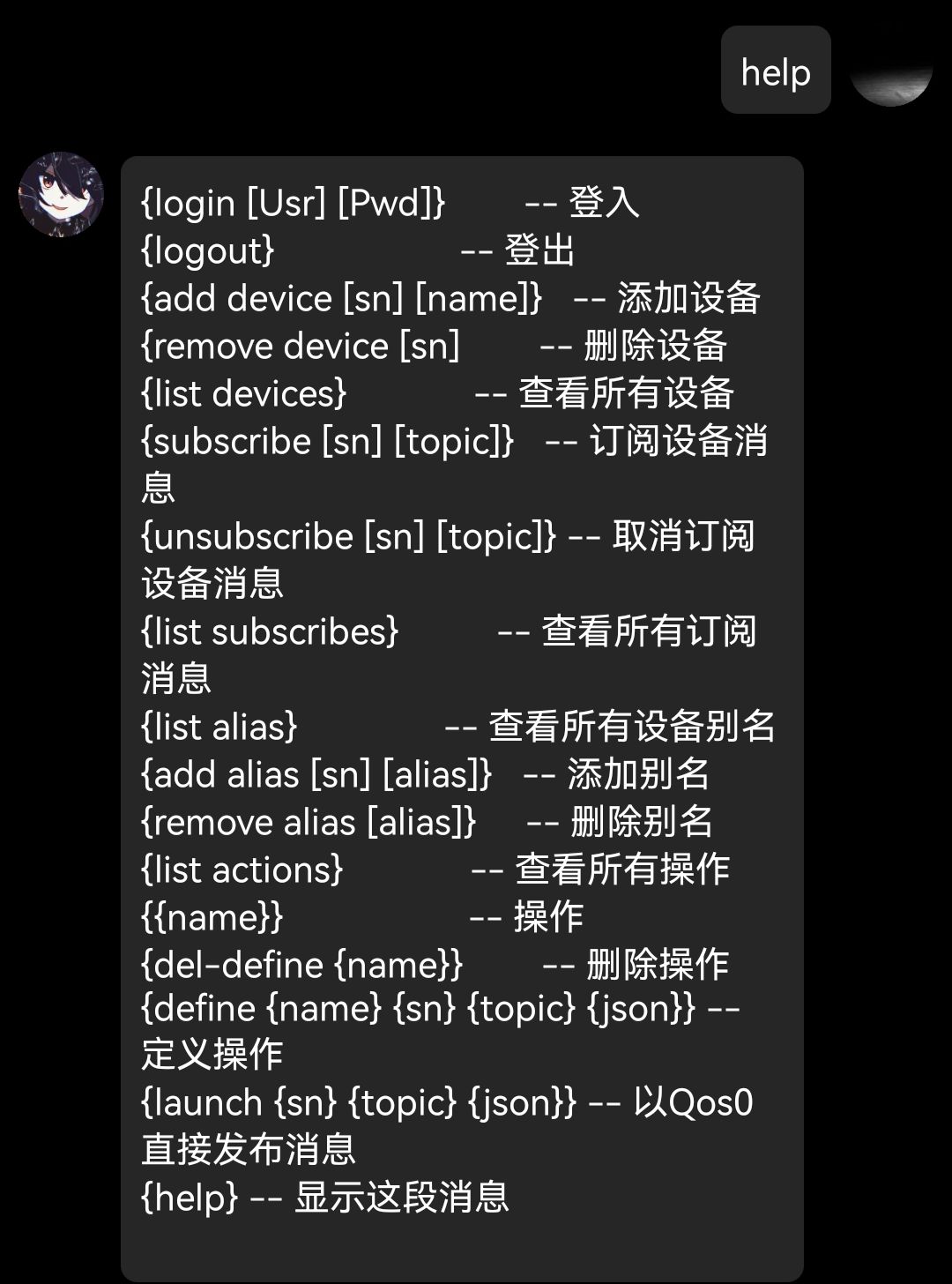
Add Devices and Behaviors
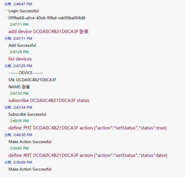
with Custom Behavior Reference
Define Operation {Operation Name} {Device Name/Alias} {subtopic} {JSON Data}
Http
root dir /api/
User Api
base dir user/
Path
Request Type
Request Body
Header
Status
Response Body
register
PUT
{ "user_name": "", "user_password": ""}
NAN
200 Successful500
login
POST
{ "key": "name/id", "pwd": "pwd" }
NAN
203 Need Authorize200 Successful401
{ "token": ""}
info
GET
NAN
Authorization: token
203 Need Authorize200 Successful401400
{ "user_id": 2, "user_name": "testUser10", "user_password": "", "user_permission_level": 100 }
logout
DELETE
NAN
Authorization: token
200 Successful500
Device Api
base dir device/
Path
Request Type
Request Body
Header
Status
Response Body
new
PUT
{ "device_sn": "DTESTSNDATA", "device_name": "TD", "device_comment": "TestComment","target_permission_level": 1}
Authorization: token
203 Need Authorize200 Successful400 Request Body Err500
delete
DELETE
{ "device_sn": "DTESTSNDATA"}
Authorization: token
203 Need Authorize200 Successful400 Request Body Err500
info
GET
{ "device_sn": "DTESTSNDATA"}
Authorization: token
203 Need Authorize200 Successful400 Request Body Err500
{ "device_id": 2, "device_name": "Name", "device_sn": "", "target_permission_level": 50 }
all
GET
NAN
Authorization: token
203 Need Authorize200 Successful500
[{ "device_id": 2, "device_name": "Name", "device_sn": "", "target_permission_level": 50 }]
Subscribe Api
base dir subscribe/
Path
Request Type
Request Body
Header
Status
Response Body
new
PUT
{ "device_sn": "TESESNDDT", "topic": "TestTopic"}
Authorization: token
203 Need Authorize200 Successful400 Request Body Err500
delete
DELETE
{ "device_sn": "TESESNDDT", "topic": "TestTopic"}
Authorization: token
203 Need Authorize200 Successful400 Request Body Err500
all
GET
NAN
Authorization: token
203 Need Authorize200 Successful500
{ "devices":[], "aliases":[]}
Alias Api
base dir alias/
Path
Request Type
Request Body
Header
Status
Response Body
new
PUT
{ "device_sn": "DTESTSNDATA", "alias": "testAlias"}
Authorization: token
203 Need Authorize200 Successful400 Request Body Err500
delete
DELETE
{ "alias": "MyRoom"}
Authorization: token
203 Need Authorize200 Successful400 Request Body Err500
all
GET
NAN
Authorization: token
203 Need Authorize200 Successful500
{ "devices":[], "aliases":[]}
Action Api
base dir action/
Path
Request Type
Request Body
Header
Status
Response Body
new
PUT
{ "action_name": "TA1", "device_sn": "TESESNDDT", "topic_name": "testTopic1", "action_json": {...}}
Authorization: token
203 Need Authorize200 Successful400 Request Body Err500
delete
DELETE
{ "action_name": "TA1"}
Authorization: token
203 Need Authorize200 Successful400 Request Body Err500
all
GET
NAN
Authorization: token
203 Need Authorize200 Successful500
{ "devices":[], "aliases":[], "actions":[]}
call
PUT
{ "action": "TA1"}
Authorization: token
203 Need Authorize200 Successful404
NAN
Assembly Instructions
Assembly Materials
M315+6 4
M466 Nuts*2
M4 Ordinary Nuts*2
PWM M35 4
2.4G Flexible Antenna IPEX
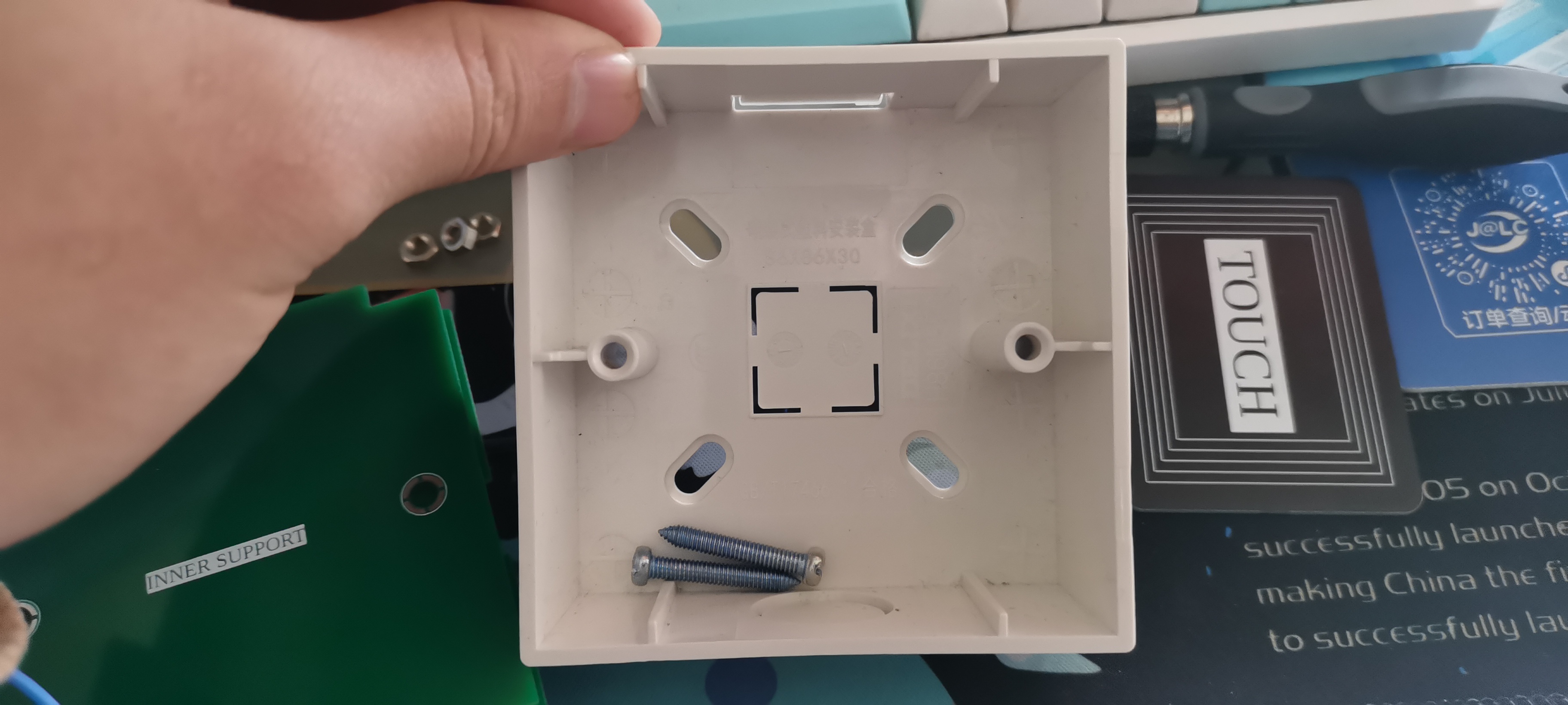
86 Blank Panel*1
86 Surface Mounted Box*1
Soldered Mainboard One
Middle Frame One
Outer Panel, One Inner Panel
Assembly Order
Mainboard Leave Touch Line
for Testing
Install Antenna
Pre-connect AC Line
Install M3 Copper Pillar
Install Middle Frame and Inner Panel
Place in 86 Box
Install Outer Panel

Appendix
Custom Voice Recognition Reference: https://mp.weixin.qq.com/s/UBoRS0SMbWdV5tyQxxjH_g
The reason for not making a single-wire system
is mainly due to the fear of problems (ghosting) when used on some lights.
Thanks to JLCPCB, the Drogon project authors and the great open source community.
Thanks to my responsible teachers Wang and Sun at my school, and everyone who has helped me at school. Thank you.
Demo video.mp4
The demonstration video on the wall.mp4
PDF_Graduation Project "Type 86" IoT Switch.zip
Altium_Graduation Project "Type 86" IoT Switch.zip
PADS_Graduation Project "Type 86" IoT Switch.zip
BOM_Graduation Project "Type 86" IoT Switch.xlsx
95610
pmw3901 flow optical flow vl53 height positioning
PMW3901 optical flow sensor and VL53 laser distance sensor enable position and height positioning.
The PMW3901 SPI communication and VL53 I2C communication can directly connect to PX4, and can also be used for custom development
. Location estimation:

PDF_pmw3901 flow optical flow vl53 height positioning.zip
Altium_pmw3901 flow optical flow vl53 height positioning.zip
PADS_pmw3901 flow optical flow vl53 height positioning.zip
BOM_pmw3901 flow optical flow vl53 height positioning.xlsx
95611
electronic


 京公网安备 11010802033920号

 ACS573MS


