1. Project Introduction
I am Zhao Xiaolin from the School of Information Science and Technology, Hunan University of Science and Technology. This project designs a synchronous buck circuit based on the EG1163s. This type of board is suitable for powering loads with relatively medium power. Here, I will explain the buck circuit and the calculation and selection of component parameters in detail.
2. Buck Circuit Introduction
A buck circuit is a DC-DC converter circuit, also known as a step-down circuit. It is a common power converter used to reduce the input voltage to a lower output voltage. The basic principle of a buck circuit is to reduce the voltage through switching operations using inductors and switching elements.
The main components of the circuit include:
1. Switching element: Usually a controllable switch, such as a MOSFET. This switch periodically turns on and off to control the operating state of the circuit.
2. Inductor: The inductor is one of the core components of the buck circuit. It stores electrical energy and releases the stored energy when the switch is off to supply the load in the circuit.
3. Output capacitor: Used to smooth the output voltage and reduce fluctuations in the output voltage.
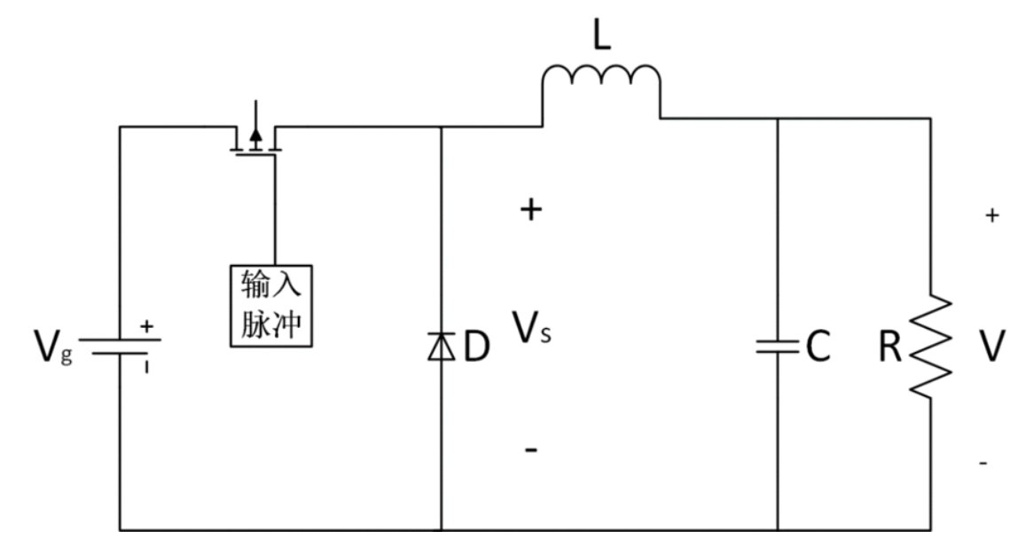
2. Working Principle of a Buck Circuit
When the switching element is off, the inductor stores energy and is responsible for maintaining current flow.
When the switching element is turned on, the inductor releases its stored energy, transferring electrical energy to the load and capacitor.
The output voltage can be adjusted by changing the switch's duty cycle and operating period.
The advantage of a buck circuit is its ability to provide a lower output voltage than the input voltage, making it suitable for applications requiring lower voltages, such as mobile devices and electronic equipment. It offers advantages such as high efficiency, simple design, and small size.
The following diagram shows the basic buck circuit model
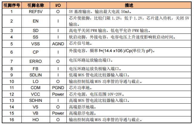
. EG1163S Introduction:
The EG1163S is a DC-DC power management chip designed by Yijing Microelectronics Co., Ltd. for high-voltage, high-current step-down voltage reduction. It integrates a reference power supply, oscillator, error amplifier, current limiting protection, and short-circuit protection. With an external high-voltage MOSFET, it supports a maximum power input voltage of 600V.
The following diagram shows the EG1163S, its pin function diagram, and internal structure diagram.

3. Component Selection:
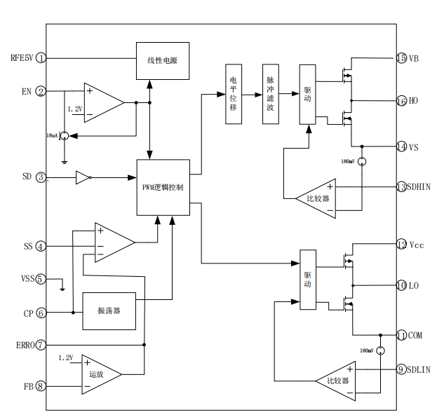
Here, I want to achieve a 18V to 12V step-down converter. The 18V input passes through four 470uf/35V electrolytic capacitors. I usually use this formula Cin=(1-D)*Iin/▲Vin*fsw to calculate the input capacitance, where D is the duty cycle, Iin is the input current, ▲Vin is the input ripple voltage, and fsw is the switching frequency. The calculated capacitance is the minimum required input capacitance. For the inductor, I chose a 22uH 40A iron-silicon-aluminum magnetic ring inductor. The inductance value was calculated using L=[Vo*(Vi-Vo)]/Vi*fsw*Iripple, where Vo is the output voltage, Vi is the input voltage, fsw is the switching frequency, and Iripple is the peak-to-peak value of the current ripple in the inductor. The ripple factor is generally taken as 20%~40%, that is, Iripple=Iout*(20%~40%). The calculated inductance is the minimum inductance value required by the circuit. When selecting an inductor, you can leave a little more margin and choose an inductor with a value slightly larger than the calculated value. Here, the calculated value was more than 15uH, but I chose a 22uH inductor.
The diagram below shows the selection of the MOSFET I chose,
which is determined by the circuit's input voltage and current. In this circuit, the input is 18V/14A and the output is 12V/20A. The Vds of the selected MOSFET must be at least greater than the voltage difference between the drain and source. However, when selecting a MOSFET, we generally choose one with a voltage approximately 10V higher than the input voltage, leaving a certain margin. The Id of the MOSFET should also be greater than the peak output current, again with a certain margin. Some parameters of the MOSFET itself are also important, such as Rds(on) and Idss. Rds(on) is the MOSFET's conduction time (dS/dt). When selecting a MOSFET, the lower the internal resistance (Rds(oN)), the better, as it primarily determines the MOSFET's conduction loss. Idss is the leakage current between the drain and source, which is the current flowing through the drain and source when the MOSFET is off; it primarily determines the MOSFET's cutoff loss. There are many other minor parameters, which I haven't delved into here. Since I already have an IRF540N MOSFET, I didn't need to buy another one. This MOSFET has a Vds of 100V, an Id of 35A, a relatively low Rds(oN) of only 30mΩ, and a relatively low Idss of only 1uA, meeting the MOSFET requirements of this design.
The following diagram shows the selection of the MOSFET and freewheeling diode I chose

. The main considerations are the device's rated reverse breakdown voltage, rated peak current, forward conduction voltage, and reverse recovery time. Here, I'm using a synchronous buck converter, so I didn't use a diode for freewheeling; instead, I used a MOSFET to replace the diode's freewheeling function.
The difference between synchronous and asynchronous buck converters lies in their circuit structure and operating principle:
Synchronous Buck:
In a synchronous buck circuit, a controller synchronously controls the switching transistor and the synchronous rectifier (usually a MOSFET) to achieve voltage reduction. The synchronous buck circuit reduces conduction losses between the switching transistor and the synchronous rectifier by turning on the synchronous rectifier when the switching transistor is off, thus improving overall efficiency. Due to the presence of the synchronous rectifier, synchronous buck circuits typically have higher conversion efficiency than traditional asynchronous buck circuits, especially under high load conditions.
Asynchronous Buck:
An asynchronous buck circuit typically contains only one switching transistor and one diode as the output rectifier, without a synchronous rectifier. In an asynchronous buck circuit, the diode acts as the output rectifier, responsible for transferring the energy released by the inductor to the load, but its forward voltage drop causes some power loss. Asynchronous buck circuits are relatively simple to design and have lower cost, but under high load conditions, their efficiency may be slightly lower than that of synchronous buck circuits due to the forward voltage drop of the diode.
Efficiency: Synchronous buck circuits generally have higher conversion efficiency than asynchronous buck circuits, especially under high load conditions.
Differences: Circuit Complexity: Synchronous Buck circuits are relatively more complex because they require a controller to synchronously control the switching transistors and synchronous rectifier. Cost: Asynchronous Buck circuits are relatively simple to design and have lower costs, while the design and manufacturing costs of synchronous Buck circuits may be slightly higher.
Applicable Scenarios: Synchronous Buck circuits are generally more suitable for applications with high efficiency requirements, while asynchronous Buck circuits are more suitable for applications with lower cost requirements.
Here, I still choose the IRF540N for freewheeling.
The following diagram shows the synchronous Buck circuit model .

The size of the output capacitor is mainly determined by the output voltage ripple requirement, which can be calculated using Cout=D*Io/▲Vi*fsw, where ▲Vi is the input voltage ripple, Io is the output current, and Fsw is the switching frequency. Here, I chose a 4700uf/35V electrolytic capacitor.
4. Circuit Design:
Placing a high-frequency, small-value bypass capacitor to ground at pin 1 (REF5V) will reduce high-frequency noise at the REF5V pin. A 1uF ceramic capacitor can be used as the bypass capacitor, placed as close as possible to the REF5V input pin during PCB layout.
Pin 2 (EN) is the enable pin. When the voltage drops below 1.2V, the chip enters standby mode and shuts down the 5V output. Here, I use a series connection of 150kJ and 15kJ capacitors to divide the input 18V and connect it to EN, effectively connecting 1.6V to EN.
Pin 3 (SD) is the low-level enable pin for PWM output; here, we directly ground it.
Pin 4 (SS) is the soft-start pin. An external capacitor is connected; the capacitor voltage rise rate affects the soft-start time. Here, a 100pF surface-mount capacitor is connected as a start-up buffer.
The five-pin VSS chip's signal ground can be grounded here.
The six-pin CP is the operating frequency control pin; the formula is: f = (14.4 * 10^6) / Cp, where the capacitor unit is pF. Here, I connected a 220pF surface-mount capacitor, resulting in a frequency of approximately 65kHz.
The seven-pin ERRO is the output port of the voltage loop op-amp; simply connect a resistor and capacitor in series with FB.
The eight-pin FB is the negative input port of the voltage loop op-amp; simply divide the output voltage and connect it to this pin. This pin internally connects to a comparator, which compares it with Vref. If the voltage at the FB pin is low, the duty cycle of the switch is increased; if it is high, the duty cycle is decreased, thus stabilizing the voltage.
The nine-pin SDLIN is the input port of the low-side MOSFET current comparator; here, a 100KΩ capacitor is connected in series with the drain of the lower MOSFET.
Pin 10 (LO) controls the turn-on and turn-off of the low-side MOSFET. Here, a 15Ω resistor, a 2Ω resistor, and a 4148 diode are connected in series and then parallel to the gate of the low-side MOSFET. The resistor and diode here speed up the turn-off without affecting the turn-on speed, thus reducing the MOSFET's power consumption.
Pin 11 (COM) is the chip's power ground; simply ground it.
Pin 12 (VCC) is the chip's power supply. Here, I first connect the input power supply in series with a 75K resistor to this pin, then connect the output 12V in series with a resistor and the 4148 diode to this pin. When the power supply is input, 18V enters the chip through the 75K resistor, and the chip instantly starts working, immediately outputting 12V. The chip can then be powered by the 12V supply, or it can be continuously powered by the input power supply. The chip's voltage range is 10~20V.
Pin 13 (SDHIN) is the input port for the high-side MOSFET current comparator. Here, a 10K resistor is connected in series to the source (S) of the high-side MOSFET.
Pin 14 (VS) is the high-side floating ground. This pin is connected to the drain (D) terminal of the upper and lower transistors, and then connected to pin 15 (VB) through a 100nF bootstrap capacitor. The bootstrap capacitor utilizes the characteristic that the voltage across a capacitor cannot change abruptly. When a certain voltage is maintained across the capacitor, increasing the voltage at the negative terminal maintains the original voltage difference at the positive terminal, effectively lifting the
voltage at the negative terminal. Pin 15 (VB) is the high-side floating power supply. The bootstrap capacitor and diode raise the potential of this pin, maintaining the voltage difference with the high-side floating ground.
Pin 16 (HO) output controls the conduction and cutoff of the high-side MOSFET, connected in the same way as pin 10.
Based on the above circuit schematic design

, the PCB design is also crucial. High-power traces should be as large as possible, and the traces controlling the MOSFET switches should have small loop areas to reduce magnetic coupling. Traces should not pass through power devices to minimize electromagnetic interference.

Finally, the duty cycle of the buck circuit is calculated using the volt-second balance of the inductor. The volt-second balance of the inductor occurs when, during the steady-state operation of the switching power supply, the voltage across the inductor integrals to zero over one cycle, thus achieving equality between the current increase and decrease over the cycle.
In this circuit, this means that when the switch is closed, the voltage across the inductor is (Vi - Vo) * D, and when the switch is open, the voltage across the inductor is -Vo * (1 - D). Adding these two equations together equals 0, so we can calculate D = Vo/Vi.
Since this board has been in development for several months and I haven't recorded any test videos, I can only provide a few pictures of the actual
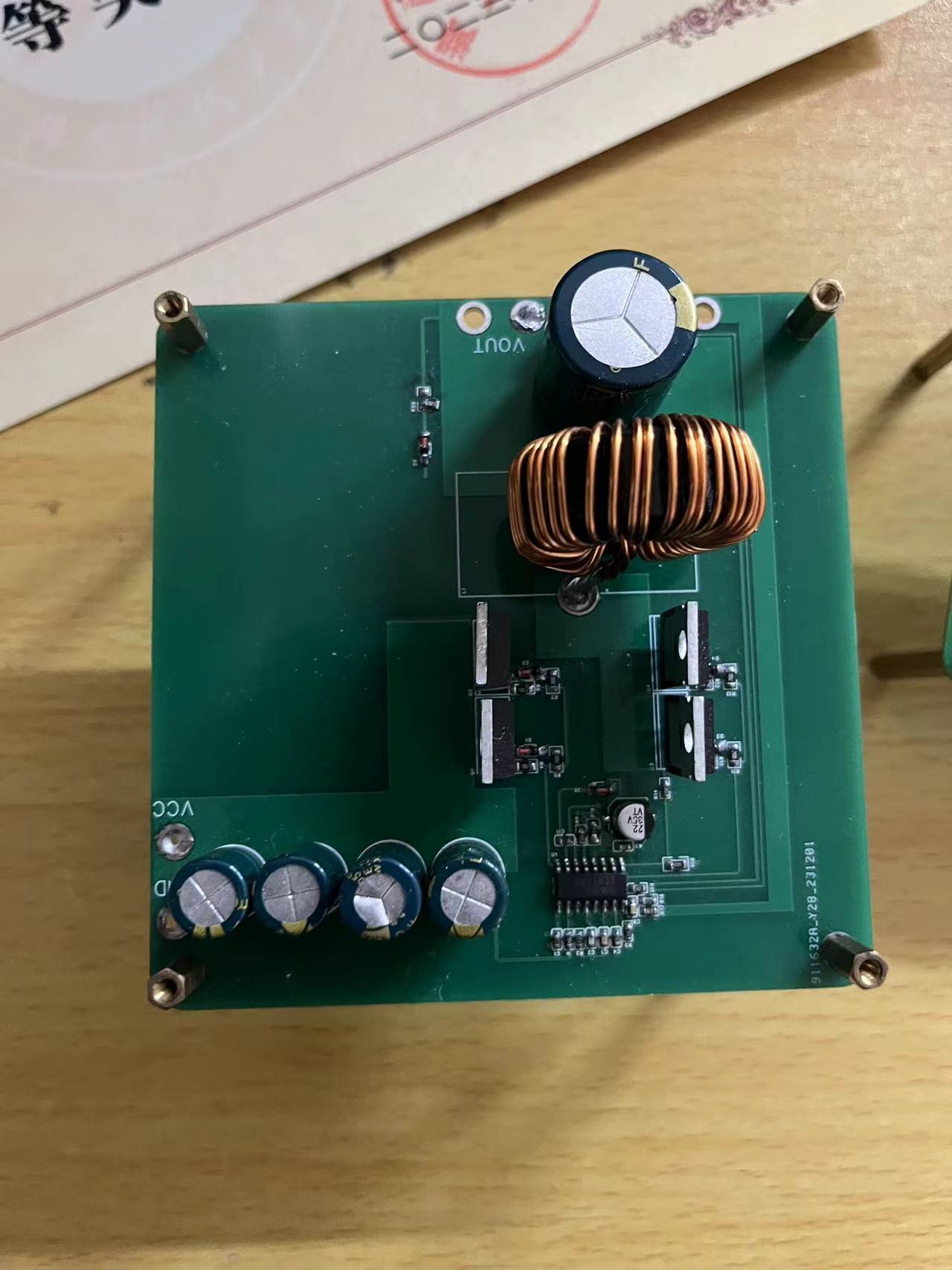
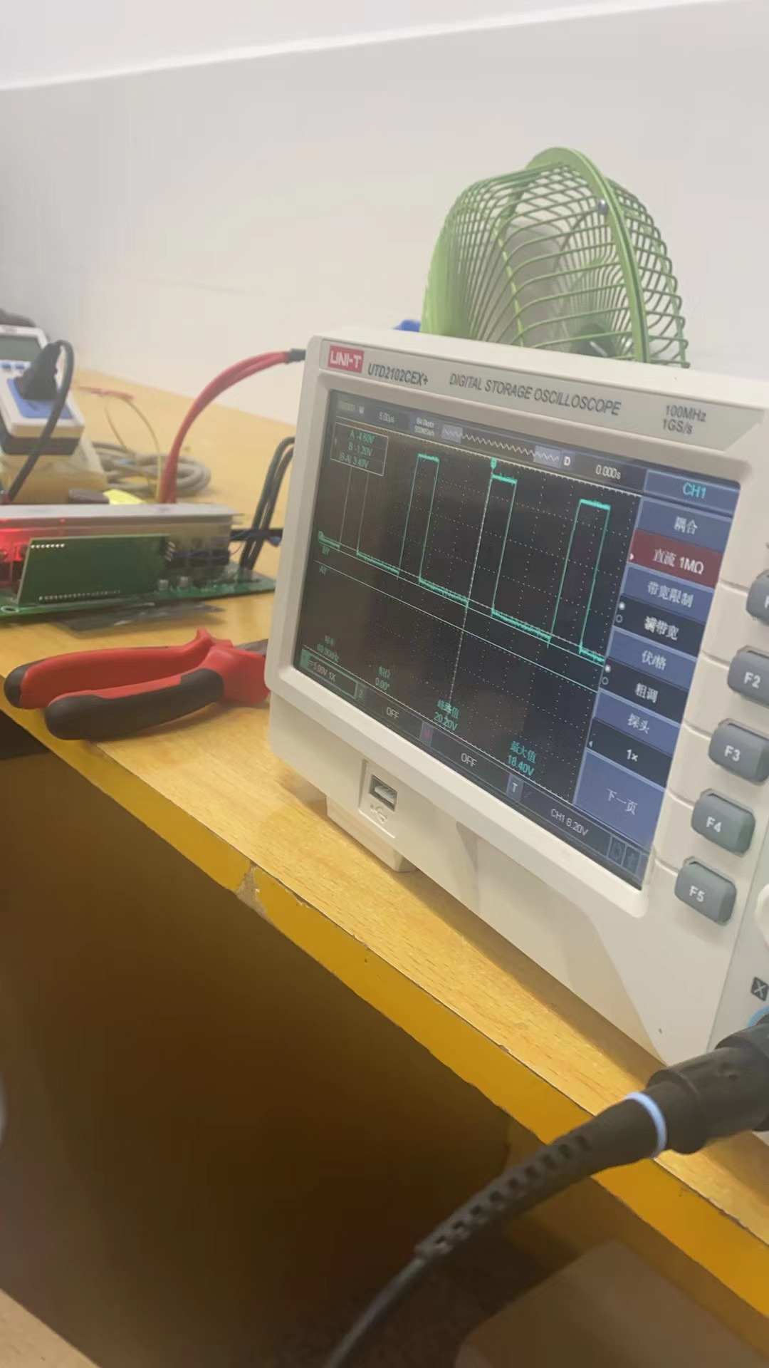
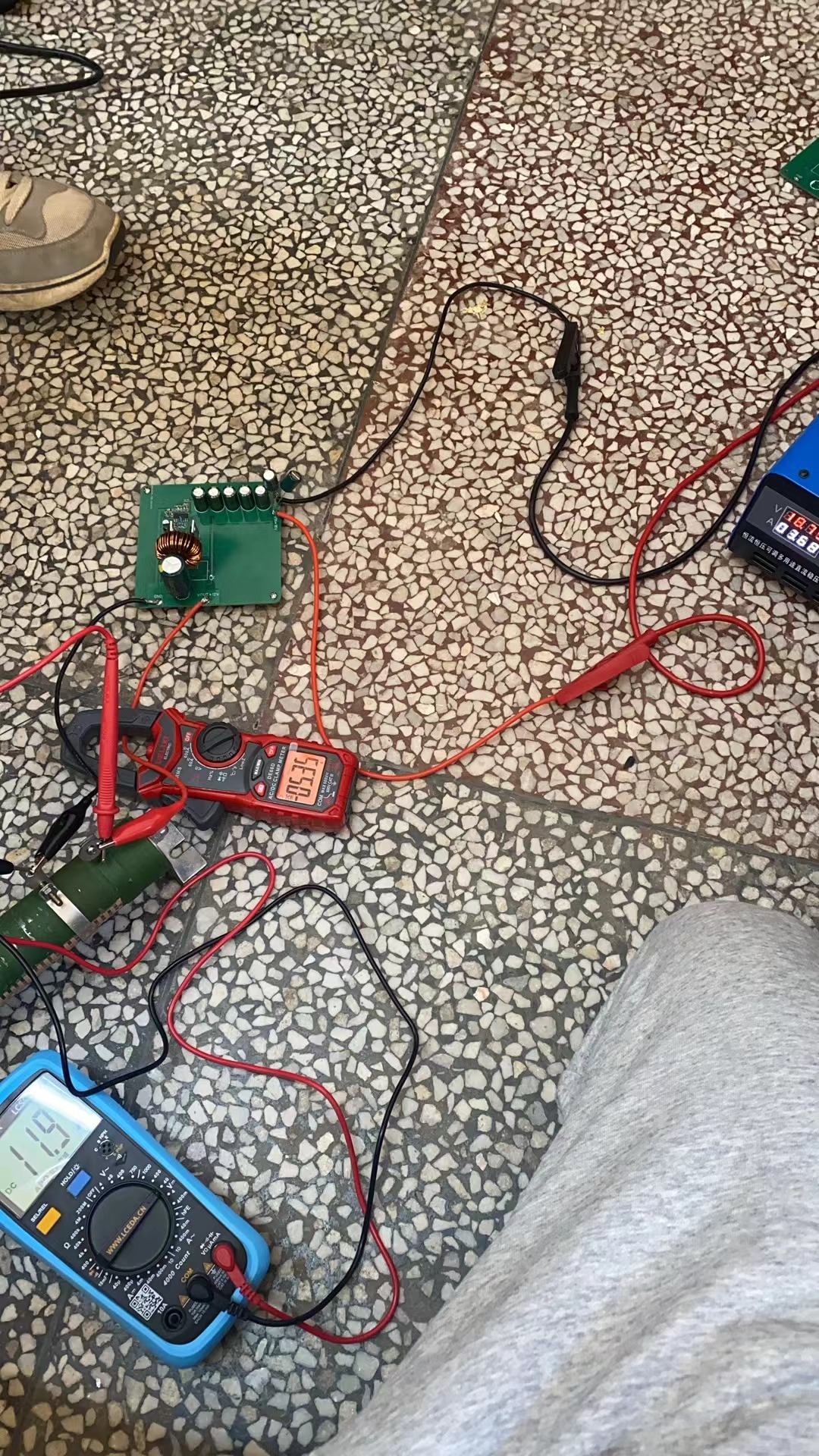
board. The board didn't reach 20A in the final test, but it can easily reach a maximum of 15A.
These are just my personal insights; please correct me if I'm wrong.


 京公网安备 11010802033920号

 HVCU0805T167K30.5%R


