Foreword Summary:
I'm not very satisfied with the breathing light effect this time. I don't recommend replicating this project. I'll come back and optimize it after I learn how to use a microcontroller to generate LEDs.
1: Project Introduction
This project uses an LM358 operational amplifier and peripheral circuitry to drive 20 LEDs of different colors.
2: Circuit Introduction
The main chip is the LM358, a dual-channel low-power differential operational amplifier. It features single or dual power supply operation. It has high open-loop gain, internal compensation, high common-mode range, good temperature stability, and output short-circuit protection. It can be applied to sensor amplifier circuits, DC amplifier modules, audio amplifier circuits, and traditional operational amplifier circuits.
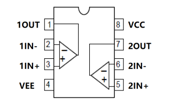
Chip Pin Definitions:

Pin Locations:
Typical Application:
The LM358 and peripheral circuitry form a triangular wave signal generator; transistors form a common-collector circuit, amplifying the triangular wave signal applied to the base. Because the base voltage is a triangular wave sandwiched between a DC signal, the emitter output voltage is an upward-shifted triangular wave signal, which can control the brightness of the LEDs, creating a breathing effect.
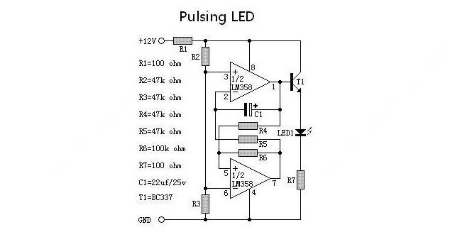
The potentials of pins 3 and 6 of the LM358 are fixed. When the potential of pin 2 is lower than that of pin 3, pin 1 outputs a high level, meaning T1 conducts and the LED lights up. The potential of pin 2 is provided by pin 7. When the potential of pin 5 is higher than that of pin 6, pin 7 outputs a high level. These two operational amplifiers form an interconnected comparator that intermittently turns on T1, lighting the LED. Draw
the schematic diagram according to the reference diagram.

After the schematic diagram is completed, draw the PCB.
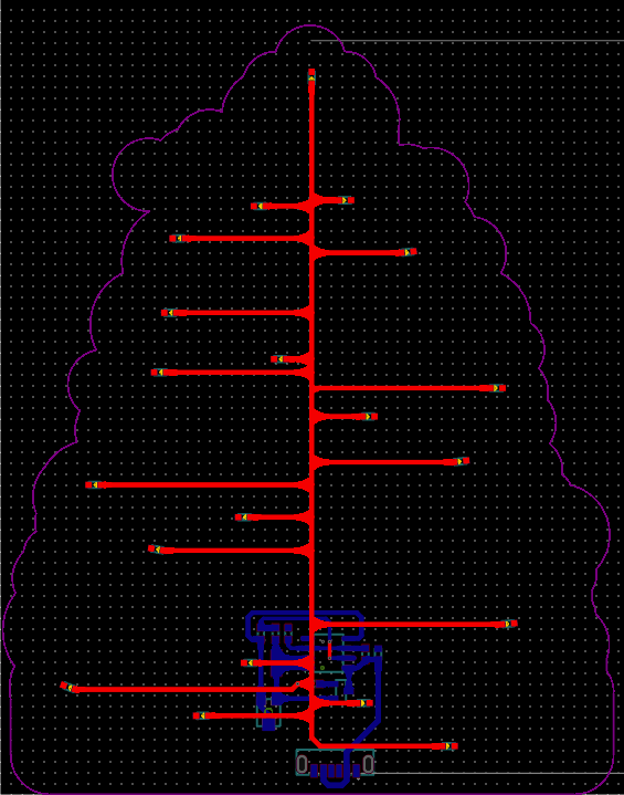
The PCB outline should be drawn in the shape of a Christmas tree
. After drawing, you can insert the prepared image to check the effect of the color silkscreen printing
. Adjust the LED positions, placing them where you want them to light up. Place the components on the back to make the front look neat and tidy. Draw the traces on the front in the shape of a tree,
echoing the image. Clean all silkscreen areas on the PCB to make the board surface clean.
PCB3D Preview


3: Physical
PCB Photos

- Front and Back

of the
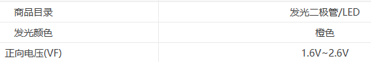
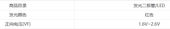
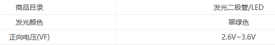
Board Summary of Problems Encountered: After the board was fully soldered, some LEDs lit up while others didn't. The cause was unknown. Measuring the voltage across the LEDs revealed only 1.6V-2.0V. Further investigation of the driver voltages for different colors revealed that the driver voltages varied. Orange and red LEDs had lower driver voltages and could be lit directly. White, blue, and green LEDs had higher driver voltages (2.6V-3.6V). The problem was identified: the different voltages caused some colors to light up while others didn't. A temporary solution was to remove the current-limiting resistors and replace them with individual resistors soldered before each red and orange LED to lower the voltage. However, soldering resistors and LEDs onto a single pad is cumbersome, but this was the only option to achieve the desired lighting effect. When all the LEDs lit up normally, a new problem was discovered: the breathing effect of the LEDs was not synchronized. This was likely due to different driving voltages. The LM358 is used to achieve the breathing effect by varying the voltage, but when two types of LEDs with different driving voltages rise and fall simultaneously, the LEDs driven by the lower voltage will light up first and then turn off, while those driven by the higher voltage will turn off before they even light up. This causes the breathing effect to be asynchronous, with some LEDs faster than others. Ultimately, it's better to use a microcontroller to directly drive the LEDs, thus avoiding the voltage effect. Ideally, a WS2812B type RGB LED should be used, as it integrates a driver chip and supports RGB colors. Once I learn how to drive WS2812B RGB LEDs, I will optimize this project again. Currently, I don't recommend replicating this project; it was a somewhat unsuccessful attempt.


 京公网安备 11010802033920号

 PIC18LF020T-I/P


