When soldering the CY7C68013, whether it's a disassembled chip or a new one, it's best to tin the pins (I soldered it twice, but it still didn't work when plugged into the computer, so I even bought a new chip online). Apply solder paste to the pads, use a hot plate or hot air gun, and apply solder paste to any bridging areas with a soldering iron.
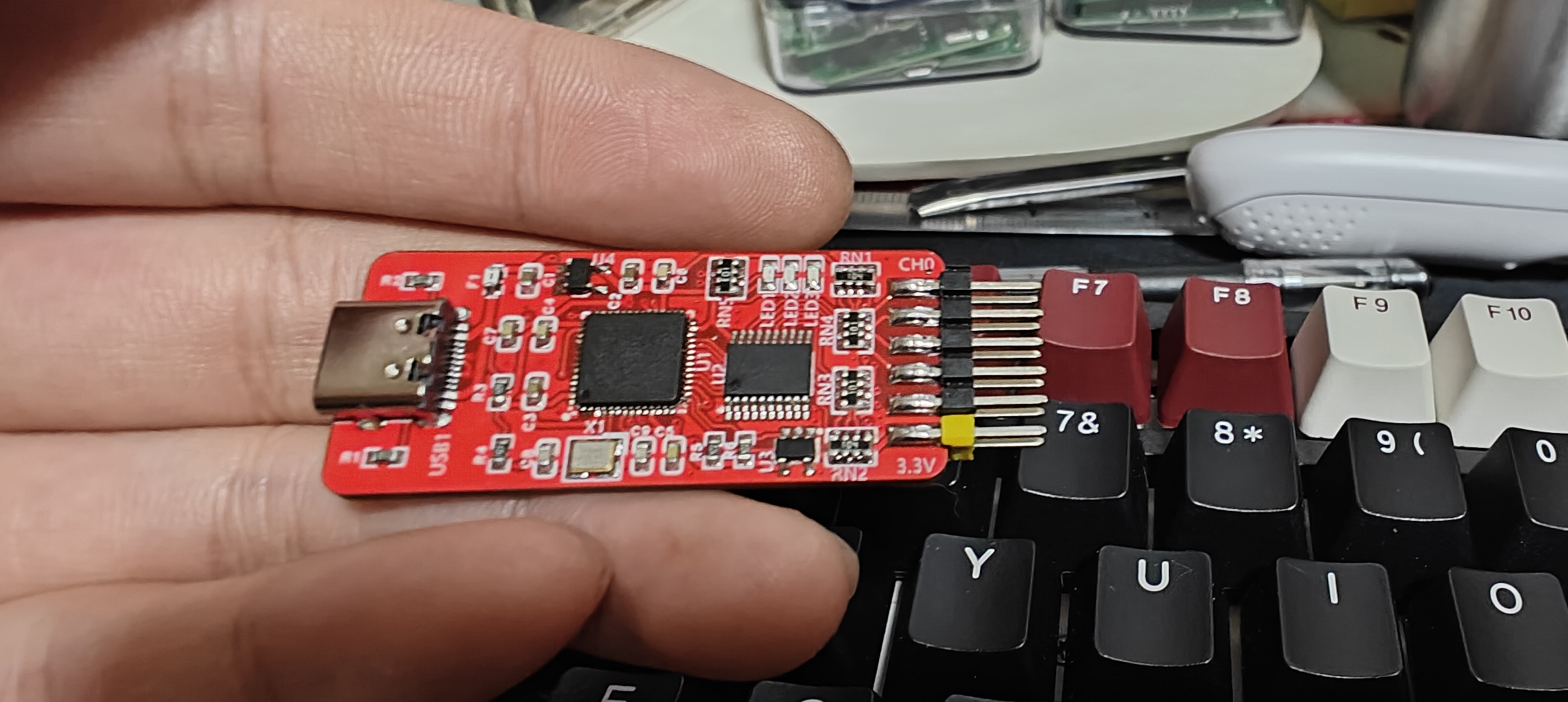
The dimensions are 20*45 cm, which is quite noticeable compared to the size of a palm.
After connecting, install the driver (you can install as administrator by right-clicking). Open CyConsole.exe, click Options to open the EZ-USB interface, click S EEPROM, and select the saleae.iic file to burn. If using a larger capacity EEPROM, click Lg EEPROM.

Download the burning software here: PulseView saleae.


PCB Logic Analyzer (copy_2023-11-4.html)
CYC68013.zip
PDF_CY7C68013 Logic Analyzer - 20_45 copies_0603 RC version.zip
Altium_CY7C68013 Logic Analyzer - 20_45 copy_0603 RC version.zip
PADS_CY7C68013 Logic Analyzer - 20_45 copy_0603 RC version.zip
BOM_CY7C68013 Logic Analyzer - 20_45 copy_0603 RC Version.xlsx
97136
Mini 5-axis motherboard with 2225 driver
A 3D printer motherboard with an STM32F103C6 main controller, a 5-axis TMC2225 driver, and stepper motors, and a 410 rod hub.
First, thank you to the user "琉璃" for their hard work in creating the wiring. This is a mini 3D printer motherboard that requires a tool head to function. An open-source 3D printer motherboard with an STM32F103C6 main controller, a 5-axis TMC2225 driver for stepper motors, and a 410 stick hub is also available.
Welcome to join the discussion group: 948104146
PDF_Mini 5-Axis Motherboard with 2225 Driver.zip
Altium Mini 5-Axis Motherboard with 2225 Driver.zip
PADS Mini 5-Axis Motherboard with 2225 Driver.zip
BOM_Mini 5-Axis Motherboard with 2225 Driver.xlsx
97137
CPU PCB
Columbia Spring 23 EE6350 design project team08: A18 Bionic
PCB design of NPU
Columbia Spring 23 EE6350 design project team08: A18 BionicPCB design of NPU
PDF_NPU PCB.zip
Altium_NPU PCB.zip
PADS_NPU PCB.zip
BOM_NPU PCB.xlsx
97139
[Original*] Color silkscreened STM32F407VET6 basic system version
This is a system board with a serial port based on the STM32F407VET6, made as a personal hobby.
Image source: Pixiv artist.

I have absolutely no experience with Photoshop. This is my
first open-source project, and I integrated it using Windows Paint. Please forgive
any shortcomings. The schematic was copied and slightly modified. It's
an STM32F407VET6 minimum system board (with USB serial port ). The
serial
port uses a CH340C
microcontroller with a built-in 1.5A self-resetting fuse for protection against sudden failure .
PE14 and PE15 are for programming control LEDs (ice blue) and a 5V LED (blue).
Please ensure the power supply voltage does not exceed 5V. I didn't consider the power supply issue when designing the CH340C serial port circuit.
I hope to provide more advice for beginners.
I don't have a hot plate or low-temperature soldering wire, so please don't ask me if my soldering is bad. This board floats as soon as I apply solder when connected to the network.

video_20231114_213834.mp4.JPG
video_20231114_213834.mp4
IMG_20231114_113507.jpg.JPG
IMG_20231114_185426.jpg.JPG
IMG_20231114_185430.jpg.JPG
PDF_【Original_】Color silkscreened STM32F407VET6 basic system version.zip
Altium_【Original_】Color silkscreened STM32F407VET6 basic system version.zip
PADS_【Original_】Color Silkscreen STM32F407VET6 Basic System Version.zip
BOM_【Original_】Color Silkscreen STM32F407VET6 Basic System Version.xlsx
97140
Multifunctional test pen
This multi-functional pen can be used to measure resistance and output PWM waveforms.
A portable multi-functional test pen with voltage measurement, continuity measurement, diode detection, and signal output functions was built based on the CW32F030.
This pen is a minor modification of the official design.
1. Main controller: CW32F030C8T6
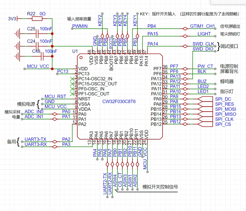
; 2. Charging circuit:
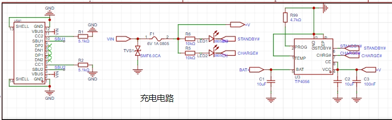
This multi-functional pen uses a TP4056 power management chip to charge the battery (the official solution uses TP4057)
. Since there are many TP4056 power management chips available, the TP4057 was not used;
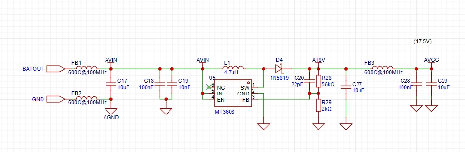
3. Power supply for the analog section;
4. Schematic diagram

(front and
back) .
Gerber_PCB1_2023-11-17.zip
CW32 Pen Schematic Diagram.pdf
PDF_Multifunctional Test Pen.zip
Altium Multi-functional Test Pen.zip
PADS_Multifunctional Test Pen.zip
BOM_Multifunctional Testing Pen.xlsx
97141
electronic


 京公网安备 11010802033920号

 MK23-90-F-2_DE