Preface:
Before starting, I was full of confidence, thinking this little gadget would be a piece of cake!
But after starting, I was completely outmaneuvered. It really proved Li Gong's words true: this thing isn't difficult in theory, but doing it well is not easy at all.
To make it truly precise is indeed very difficult, especially current measurement, which I'll discuss later.
In short, the simpler something looks, the more difficult it is to do.
Finally, thank you to all the experts, and thank you to LCSC for giving me this opportunity. This was the most memorable project for me; there were so many pitfalls.
Principle Introduction
: A power meter calculates the power consumption of electronic products. It's usually measured in watts or milliwatts.
Two data points need to be measured: first, voltage u, which is the voltage drop;
second, current i.
Therefore, power P = u * i. The principle is that simple.
It looks simple, but doing it is not.
Hardware Design:
The following will introduce the entire circuit in sections.
The main control chip
chosen this time is the CW32F030C8T6. This ARM M0 core chip features the following characteristics:
• Core: ARM® Cortex®-M0+
with a maximum clock speed of 64MHz
• Operating temperature: -40℃ to 105℃; Operating voltage: 1.65V to 5.5V
• Storage capacity
: Maximum 64KB FLASH, data retention for 25 years @ 85℃;
Maximum 8KB RAM with parity support;
128KB OTP memory •
CRC hardware calculation unit;
Reset and power management:
Low-power modes (Sleep, DeepSleep)
; Power-on and power-down reset (POR/BOR);
Programmable low-voltage detector (LVD)
• Clock management:
4 ~ 32MHz crystal oscillator;
32kHz low-speed crystal oscillator;
Built-in 48MHz RC oscillator;
Built-in 32kHz RC oscillator
; Built-in 10kHz RC oscillator; Built
-in 150kHz RC oscillator;
Built-in PLL phase-locked
loop clock monitoring system
allows independent shutdown of peripheral clocks
• Supports up to 39 I/O interfaces;
All I/O... This chip features interrupt support
for all I/O ports, interrupt input filtering,
a five-channel DMA controller , a 12-bit analog-to-digital
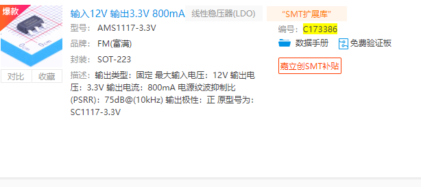
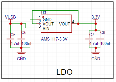
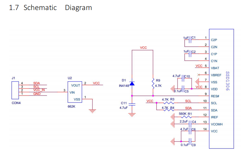
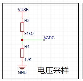
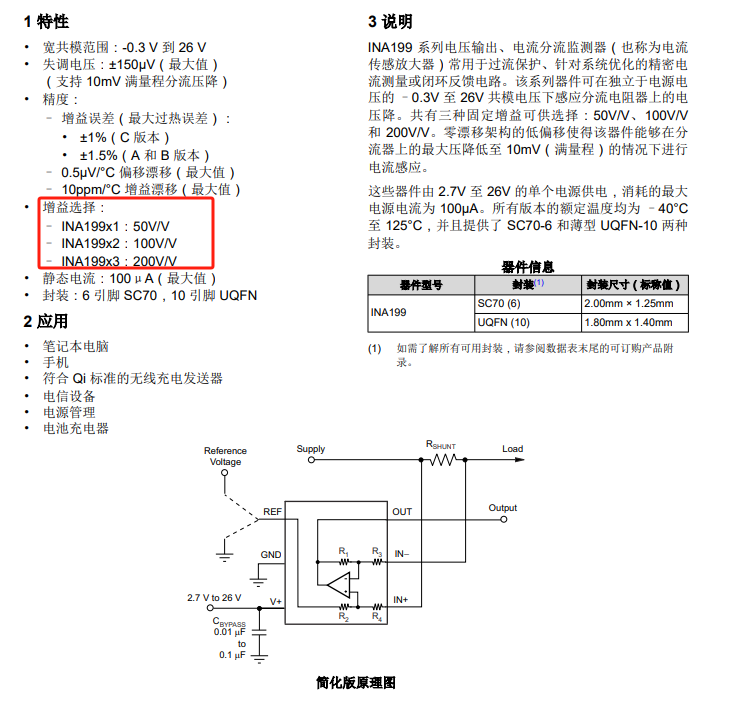
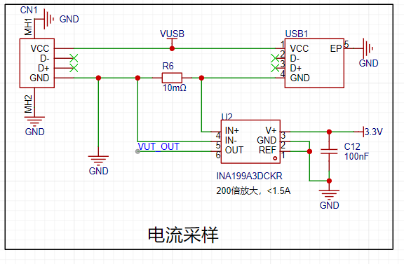
converter with ±1 LSB and a maximum 1M SPS conversion speed, a built-in voltage reference, an analog watchdog function , a built-in temperature sensor , dual voltage comparators , a real-time clock and calendar with sleep/deep-sleep wake-up mode , a 16-bit advanced control timer supporting 6 capture/compare channels and 3 pairs of complementary PWM outputs, dead time, and flexible synchronization, four 16-bit general-purpose timers, three 16-bit basic timers, a window watchdog timer , and an independent watchdog timer . Communication interfaces include three low-power UARTs supporting fractional baud rates, two SPI interfaces (12 Mbit/s), two I2C interfaces (1 Mbit/s) , an IR modulator, and a serial debug interface (SWD). This chip boasts low power consumption, various packages, is domestically produced, and is offered at a competitive price; it's a highly recommended choice. This project uses few pins, mainly controlling the following interfaces : ADC: power and current serial port; debugging and printing; IIC: control of the display screen schematic is as follows: Although the power supply section uses a USB power meter, considering the possibility of measuring larger voltages, an LDO was chosen, supporting a maximum input of 12V. This is generally sufficient. Output is 3.3V, maximum 800mA. This is also for future use with multiple fixed 3.3V output voltage modules. Therefore, the overall measured voltage should not exceed 12V. The specific implementation schematic is as follows: The display screen uses a 0.91-inch white text screen. 128x32, it can display four lines. The interface and dimensions are as follows: This is modular, the internal circuit is as follows, the IIC does not require pull-up resistors, the module has them built-in. It works very well. Therefore, the schematic design of this project only needs to reserve interfaces, as shown below: For cost savings, a voltage divider circuit is directly used in the voltage acquisition circuit, as shown in the diagram below . Note: The CW32 community suggests adding a resistor to the VADC. Personally, I think if you have the budget, you can use an operational amplifier circuit or a voltage follower circuit to improve driving capability and reduce impedance. This is just my personal suggestion. The VADC uses PA1 for sampling. The current acquisition circuit generates a voltage drop by connecting a small resistor in series. Then, the TI chip INA199A3DCKR is used as a dedicated current sensing amplifier. There are three options; I chose the 200x one. If you are measuring small currents, choose the 50x or 100x one. The corresponding models are as follows: I chose the 200x A3, which uses a reference voltage of 2.5V with the CW32 ADC. This is the internal configuration of the CWF030; there are also 3.3V and 1.5V options available, but I chose 2.5V. Therefore, the maximum current Imax = 2.5/200/0.01 = 1.25A. For commonly used computer USB ports, this value is sufficient. If you find it too high or too low, you can choose different amplifiers with different voltage references. For example, if I choose 3.3V, then Imax = 1.65A, which will not be accurate for testing small currents. The smaller the range, the more accurate the measurement; please refer to this rule. *Based on the previous maximum voltage of 12V, the load power Pmax = 121.25 = 15W. It absolutely cannot be higher. Higher values may cause smoke. ** The principle design is as follows: **


The indicator lights
here use colored LEDs, specifically the WS2812, which is quite popular and cool recently.
The circuit is very simple, as shown below. The driver hasn't been written yet; I'll update the software in the second version.

Regarding the other download, reset, and mode circuits , I'll only discuss the reset circuit here. Due to DAP debugging, a soft reset
isn't possible, so it's best to leave a hardware reset interface or connect it directly to the downloader's RST; otherwise, it's quite troublesome.
The specific schematic is as follows:

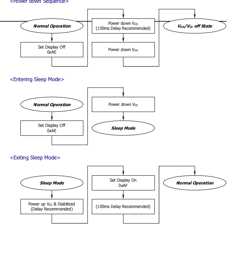
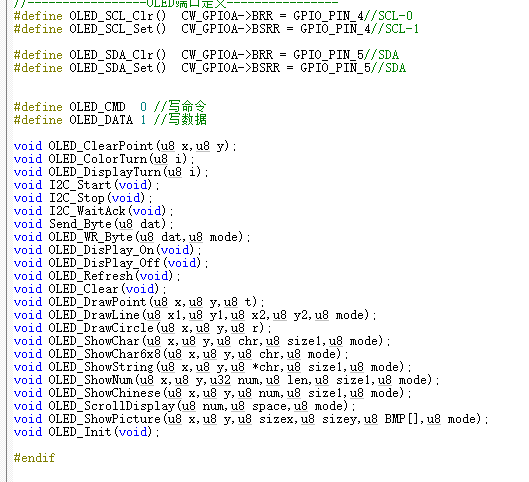
The software implementation
will also be explained in several parts. The display part mainly involves the IIC driver; for SSD106, simply refer to the official initialization function. The flowchart is as follows . The OLED initialization function is as follows: As for using text or images, we can use image extraction software. The detailed code is too long to paste here. You can refer to the relevant functions. The ADC acquisition part uses pins PA1 and PA2 to acquire voltage and current respectively. If related files need modification, it's best to refer to the manual and write your own; this is suitable for direct replication. I spent too much time on this part, encountering various errors and pitfalls. In short, please take it seriously. The relevant configuration functions are as follows: ifndef __ADC_H define __ADC_H ifdef __cplusplus extern "C" { endif / Includes ------------------------------------------------------------------/ include "base_types.h" include "cw32f030.h" include "system_cw32f030.h" include "interrupts_cw32f030.h" include "cw32f030_systick.h" include "cw32f030_rcc.h" include "cw32f030_gpio.h" include "cw32f030_adc.h" extern uint16_t gAdcResult[4]; void ADC_Config(void); uint8_t Gain_Value(void); ifdef __cplusplus } endif endif / __ADC_H / The implementation file of adc.c is as follows: /** Include files **/include "adc.h" /** Local pre-processor symbols/macros ('#define') **/ / USER CODE BEGIN EM / / Sequence channel continuous sampling mode/ //#define SQR_CONTINUOUS_MODE_EN / Sequence channel scan sampling mode/ define SQR_SCAN_MODE_EN / Sequence channel multiple sampling mode/ //#define SQR_MORE_MODE_EN / Sequence channel discontinuous sampling mode/ //#define SQR_BREAK_MODE_EN / USER CODE END EM / /** Global variable definitions (declared in header file with 'extern') **/ /** Local type definitions ('typedef') **/ /** Local function prototypes ('static') **/ /** Local variable definitions ('static') * **/ uint16_t valueAdc; uint16_t gAdcResult[4]; uint32_t valueAdcAcc; volatile uint8_t gFlagIrq; uint16_t gCntEoc = 0; uint8_t cntSample; /** Local pre-processor symbols/macros ('#define') **/ /***** Function implementation - global ('extern') and local ('static') **/ /** @brief ADC I/O initialization */ void ADC_PortInit(void) { // Enable GPIO clock REGBITS_SET(CW_SYSCTRL->AHBEN, SYSCTRL_AHBEN_GPIOA_Msk); // Enable ADC clock REGBITS_SET(CW_SYSCTRL->APBEN2,SYSCTRL_APBEN2_ADC_Msk); //set PA01 as AIN1 INPUT PA01_ANALOG_ENABLE();


//set PA02 as AIN2 INPUT
PA02_ANALOG_ENABLE();
// //set PA05 as AIN5 INPUT
// PA06_ANALOG_ENABLE();
// //set PA07 as AIN7 INPUT
// PA07_ANALOG_ENABLE();
}
void ADC2_Config(void)
{
ADC_InitTypeDef ADC_InitStructure;
ADC_SerialChTypeDef ADC_SerialChStructure;
//Configure ADC test I/O port
ADC_PortInit();
//ADC initialization
// ADC_InitStructure.ADC_SampleTime=ADC_SampTime10Clk;
// ADC_InitStructure.ADC_VrefSel=ADC_Vref_BGR1p5;
ADC_StructInit(&ADC_InitStructure);
//ADC working clock configuration
ifdef SQR_BREAK_MODE_EN
ADC_InitStructure.ADC_ClkDiv = ADC_Clk_Div1;
else
ADC_InitStructure.ADC_ClkDiv = ADC_Clk_Div16;
endif
// ADC sequence scan conversion mode configuration
ADC_SerialChStructure.ADC_Sqr0Chmux = ADC_SqrCh1;//ADC_SqrVddaDiV3; //ADC_SqrCh1;
ADC_SerialChStructure.ADC_Sqr1Chmux = ADC_SqrCh2; //ADC_SqrCh2; //
// ADC_SerialChStructure.ADC_Sqr2Chmux = ADC_SqrCh6; //ADC_SqrCh5;
// ADC_SerialChStructure.ADC_Sqr3Chmux = ADC_SqrCh7;
ADC_SerialChStructure.ADC_SqrEns = ADC_SqrEns01;
ADC_SerialChStructure.ADC_InitStructure = ADC_InitStructure;
ifdef SQR_CONTINUOUS_MODE_EN
/ Serial channel continuous sampling mode /
ADC_SerialChContinuousModeCfg(&ADC_SerialChStructure);
ADC_ITConfig(ADC_IT_EOS, ENABLE);
elif defined (SQR_SCAN_MODE_EN)
/ Serial channel scan sampling mode /
ADC_SerialChScanModeCfg(&ADC_SerialChStructure);
ADC_ITConfig(ADC_IT_EOS, ENABLE);
elif defined (SQR_MORE_MODE_EN)
/ Serial channel multiple sampling mode /
cntSample = 0xFF; // Conversion count is 0xFF + 1.
ADC_SerialChMoreModeCfg(&ADC_SerialChStructure, cntSample);
ADC_ITConfig(ADC_IT_EOC | ADC_IT_EOA, ENABLE);
elif defined (SQR_BREAK_MODE_EN)
/ Serial channel intermittent sampling mode /
ADC_SerialChBreakModeCfg(&ADC_SerialChStructure);
ADC_ITConfig(ADC_IT_EOC | ADC_IT_EOS, ENABLE);
else
error "Please select ADC's running mode first in main.h!"
endif
//ADC_ITConfig(ADC_IT_EOC | ADC_IT_EOS | ADC_IT_EOA, ENABLE);
ADC_EnableIrq(ADC_INT_PRIORITY);
ADC_ClearITPendingAll();
//ADC enable
ADC_Enable();
ADC_SoftwareStartConvCmd(ENABLE);
}
uint8_t Gain2_Value(void)
{
uint8_t temp=0;
ifdef SQR_CONTINUOUS_MODE_EN
/ Serial channel continuous sampling mode /
while (!(gFlagIrq & ADC_ISR_EOS_Msk));
gFlagIrq = 0u;
//while(!(gFlagIrq & ADC_ISR_EOS_Msk));
ADC_GetSqr0Result(gAdcResult);
ADC_GetSqr1Result(&gAdcResult[1]);
// ADC_GetSqr2Result(&gAdcResult[2]);
// ADC_GetSqr3Result(&gAdcResult[3]);
//printf("ch1:%5d-ch2:%5d-ch6:%5d-ch7:%5d
",gAdcResult[0],gAdcResult[1],gAdcResult[2],gAdcResult[3]);
elif defined (SQR_SCAN_MODE_EN)
/ Sequence channel scan sampling mode /
while (!(gFlagIrq & ADC_ISR_EOS_Msk));
gFlagIrq = 0u; ADC_GetSqr0Result (gAdcResult); ADC_GetSqr1Result(&gAdcResult[1]); //
ADC_GetSqr2Result (&gAdcResult[2]); //
ADC_GetSqr3Result(&gAdcResult[3]); //printf("ch1:%5d-ch2:%5d-ch6:%5d-ch7:%5d ",gAdcResult[0], gAdcResult[1],gAdcResult[2], ...3]); //printf("ch1:%5d-ch2:%5d-ch6:%5d-ch7:%5d " ,gAdcResult[3]); //printf("ch1:%5d-ch2:%5d-ch6:%5d-ch7:% ",gAdcResult[0],gAdcResult[1],gAdcResult[2],gAdcResult[3]); elif defined (SQR_MORE_MODE_EN) / Sequence channel multiple sampling mode/ while (!(gFlagIrq & ADC_ISR_EOA_Msk)); gFlagIrq = 0u; ADC_GetSqr0Result(gAdcResult); //Get data. ADC_GetSqr1Result(&gAdcResult[1]); // ADC_GetSqr2Result(&gAdcResult[2]); // ADC_GetSqr3Result(&gAdcResult[3]); ADC_GetAccResult(&valueAdcAcc); if (gCntEoc != (cntSample + 1)) { temp=1; } //printf("ch1:%5d-ch2:%5d-ch6:%5d-ch7:%5d ",gAdcResult[0],gAdcResult[1],gAdcResult[2],gAdcResult[3]); gCntEoc = 0u; elif defined (SQR_BREAK_MODE_EN) / Sequence channel intermittent sampling mode/ while (!(gFlagIrq & ADC_ISR_EOC_Msk)); gFlagIrq &= (~ADC_ISR_EOC_Msk); if (gFlagIrq & ADC_ISR_EOS_Msk) { gFlagIrq = 0u; ADC_GetSqr0Result(gAdcResult); ADC_GetSqr1Result(&gAdcResult[1]); // ADC_GetSqr2Result(&gAdcResult[2]); // ADC_GetSqr3Result(&gAdcResult[3]); //printf("ch1:%5d-ch2:%5d-ch6:%5d-ch7:%5d ",gAdcResult[0],gAdcResult[1],gAdcResult[2],gAdcResult[3]); } endif ifndef SQR_CONTINUOUS_MODE_EN ADC_SoftwareStartConvCmd(ENABLE); //Start the next ADC conversion endif return temp; } Serial port output implementation To facilitate debugging, serial port 1, print output, etc. are implemented. The implementation function is as follows: /** Include files **/include "uart1.h" /** Local pre-processor symbols/macros ('#define') **/ //UARTxdefine DEBUG_USARTx CW_UART1 define DEBUG_USART_CLK RCC_APB2_PERIPH_UART1 define DEBUG_USART_APBClkENx RCC_APBPeriphClk_Enable2 define DEBUG_USART_UclkFreq 8000000 //UARTx GPIO define DEBUG_USART_GPIO_CLK RCC_AHB_PERIPH_GPIOA define DEBUG_USART_TX_GPIO_PORT CW_GPIOA define DEBUG_USART_TX_GPIO_PIN GPIO_PIN_8 define DEBUG_USART_RX_GPIO_PORT CW_GPIOA define DEBUG_USART_RX_GPIO_PIN GPIO_PIN_9 //GPIO AF define DEBUG_USART_AFTX PA08_AFx_UART1TXD() define DEBUG_USART_AFRX PA09_AFx_UART1RXD() /** Local variable definitions ('static') * **/ifdef __GNUC__
/ With GCC/RAISONANCE, small printf (option LD Linker->Libraries->Small printf
set to 'Yes') calls __io_putchar() /
define PUTCHAR_PROTOTYPE int __io_putchar(int ch)
else
define PUTCHAR_PROTOTYPE int fputc(int ch, FILE *f)
endif / __GNUC__ /
/**
Local pre-processor symbols/macros ('#define')
**/
/**
@brief Retargets the C library printf function to the USART.
*/
PUTCHAR_PROTOTYPE
{
USART_SendData_8bit(DEBUG_USARTx, (uint8_t)ch);
while (USART_GetFlagStatus(DEBUG_USARTx, USART_FLAG_TXE) == RESET);
return ch;
}
/**
@brief Configure GPIO
*/
void UART1_GPIO_Configuration(void)
{
GPIO_InitTypeDef GPIO_InitStructure;
RCC_AHBPeriphClk_Enable(DEBUG_USART_GPIO_CLK, ENABLE);
DEBUG_USART_APBClkENx(DEBUG_USART_CLK, ENABLE);
//UART TX RX multiplexing
DEBUG_USART_AFTX;
DEBUG_USART_AFRX;
GPIO_InitStructure.Pins = DEBUG_USART_TX_GPIO_PIN;
GPIO_InitStructure.Mode = GPIO_MODE_OUTPUT_PP;
GPIO_InitStructure.Speed = GPIO_SPEED_HIGH;
GPIO_Init(DEBUG_USART_TX_GPIO_PORT,&GPIO_InitStructure)
;
GPIO_InitStructure.Mode = GPIO_MODE_INPUT_PULLUP;
GPIO_Init(DEBUG_USART_RX_GPIO_PORT, &GPIO_InitStructure);
}
/**
@brief Configure UART
*/
void UART1_Configuration(uint32_t BaudRate)
{
USART_InitTypeDef USART_InitStructure;
USART_InitStructure.USART_BaudRate = BaudRate;
USART_InitStructure.USART_Over = USART_Over_16;
USART_InitStructure.USART_Source = USART_Source_PCLK;
USART_InitStructure.USART_UclkFreq = DEBUG_USART_UclkFreq;
USART_InitStructure.USART_StartBit = USART_StartBit_FE;
USART_InitStructure.USART_StopBits = USART_StopBits_1;
USART_InitStructure.USART_Parity = USART_Parity_No ;
USART_InitStructure.USART_HardwareFlowControl = USART_HardwareFlowControl_None;
USART_InitStructure.USART_Mode = USART_Mode_Rx | USART_Mode_Tx;
USART_Init(DEBUG_USARTx, &USART_InitStructure);
}
/**
@brief Send an 8-bit array
@param USARTx : USARTx peripheral
parameters can be:
CW_UART1, CW_UART2, CW_UART3
@param TxBuf : The array to be sent
@param TxCnt : The number of array elements to be sent
/
void UART1_SendBuf_Polling(uint8_t TxBuf, uint8_t TxCnt)
{
while (TxCnt)
{
USART_SendData_8bit(CW_UART1, *TxBuf);
while (USART_GetFlagStatus(CW_UART1, USART_FLAG_TXE) == RESET);
TxBuf++;
TxCnt--;
}
while (USART_GetFlagStatus(CW_UART1, USART_FLAG_TXBUSY) == SET);
}
/**
@brief Receive 8-bit array
@param USARTx : USARTx peripheral
parameters can be:
CW_UART1, CW_UART2, CW_UART3
@param RxBuf : Receive Buf
@return uint8_t : Number of characters received
/
uint8_t UART1_RecvBuf_Polling(uint8_t RxBuf)
{
uint8_t RxCnt = 0;
do
{
//Wait for RC
while (USART_GetFlagStatus(CW_UART1, USART_FLAG_RC) == RESET);
//Clear RC
USART_ClearFlag(CW_UART1, USART_FLAG_RC);
//ERROR: PE or FE
if (USART_GetFlagStatus(CW_UART1, USART_FLAG_PE | USART_FLAG_FE))
{
USART_ClearFlag(CW_UART1, USART_FLAG_PE | USART_FLAG_FE);
RxCnt = 0x00;
}
else
{
RxBuf[RxCnt] = USART_ReceiveData_8bit(CW_UART1);
RxCnt++;
}
}
while (RxBuf[RxCnt - 1] != '
');
return RxCnt;
}
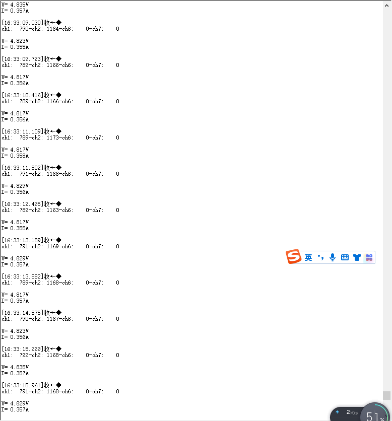
The effect is as follows:
The main control function
executes in the following order:
First, it initializes various configurations, such as clock, GPIO, serial port, and screen configuration.
Then, it performs data acquisition and screen refresh in a loop, with a 500ms delay function added in between.
The specific code is as follows:
/**/
/ file main.c
A detailed description is available at
@link Sample Group Some description @endlink
- 2021-03-12 1.0 xiebin First version for Device Driver Library of Module.
****/
/***
Code License and Disclaimer Information
Wuhan Xinyuan Semiconductor Co., Ltd. grants you a non-exclusive copyright license to use all programming code examples, from which you can
generate similar functions customized to your specific needs. Subject to any statutory warranties that cannot be excluded, Wuhan Xinyuan
Semiconductor Co. Ltd., its program developers, and suppliers make no express or
implied warranties or conditions regarding the program or technical support (if any), including but not limited to implied warranties
or conditions of merchantability, fitness for a particular purpose, and non-infringement.
In no event shall Wuhan Xinyuan Semiconductor Co., Ltd., its program developers, or suppliers be liable for any of the following,
even if advised of the possibility of their occurrence: loss or damage to data; direct, special, incidental
, or indirect damages, or any consequential economic damages; or loss of profits, business, revenue, goodwill, or anticipated savings
.
Some jurisdictions do not allow any exclusions or limitations on direct, incidental, or consequential damages, so some or
all of the above exclusions or limitations may not apply to you.
***/
/**
Include files
**/include "main.h"
/**
Local pre-processor symbols/macros ('#define')
**/
/**
Global variable definitions (declared in header file with 'extern')
**/
extern uint16_t gAdcResult[4];
/**
Local type definitions ('typedef')
**/
/**
Local function prototypes ('static')
**/
/**
Local variable definitions ('static') *
**/
uint8_t TxRxBufferSize;
uint8_t TxRxBuffer[] = "
CW32F030 UART Polling
";
/**
Local pre-processor symbols/macros ('#define')
**/
/*****
Function implementation - global ('extern') and local ('static')
**/
/**
rief Main function of project
eturn uint32_t return value, if needed
**/
int32_t main(void)
{
uint8_t flag=0;
float x,y,z;
//char s[20];
//SYSCLK = HSI = 8MHz = HCLK = PCLK
RCC_HSI_Enable(RCC_HSIOSC_DIV6);
//Configure GPIO
UART1_GPIO_Configuration();
//Configure UART
UART1_Configuration(9600);
OLED_Init(); //Initialize OLED
OLED_Clear();
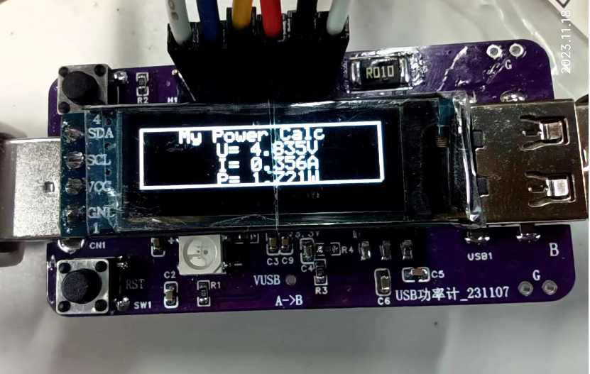
OLED\_ShowString(20,1,"My Power Calc",8,1);//6*8
UART1_SendBuf_Polling(TxRxBuffer, ARRAY_SZ(TxRxBuffer) - 1);
for(uint8_t i=0;i<3;i++)
{
delay1ms(500);
printf("hello kwin
");
}
ADC2_Config();
while (1)
{
char s[20];
flag=Gain2_Value();
if(!flag)
{
printf("
ch1:%5d-ch2:%5d-ch6:%5d-ch7:%5d
",gAdcResult[0],gAdcResult[1],gAdcResult[2],gAdcResult[3]);
//printf("ch1:%5d
",gAdcResult[0]);
x=gAdcResult[0]/4095.025;
sprintf(s,"U=%6.3fV",x);
printf("
U=%6.3fV
",x);
OLED_ShowString(40,9,s,8,1);//68
//printf("ch2=%5d
",gAdcResult[1]);
y=gAdcResult[1]/4095.01.25;
sprintf(s,"I=%6.3fA",y);
printf("I=%6.3fA
",y);
OLED_ShowString(40,17,s,8,1);//68
z=xy;
sprintf(s,"P=%6.3fW",z);
OLED_ShowString(40,25,s,8,1);//68
}else{printf("Get Value failed
");}
OLED\_DrawLine(0,0,127,0,1);
OLED\_DrawLine(127,0,127,31,1);
OLED\_DrawLine(0,0,0,31,1);
OLED\_DrawLine(0,31,127,31,1);
OLED\_DrawLine(0,31,127,31,1);
//OLED\_DrawCircle(63,31,16);
OLED_Refresh();
delay1ms(500);
}
}
/**
@brief Configure RCC
*/
/**
EOF (not truncated)
**/ifdef USE_FULL_ASSERT
/**
@brief Reports the name of the source file and the source line number
where the assert_param error has occurred.
@param file: pointer to the source file name
@param line: assert_param error line source number
@retval None
/
void assert_failed(uint8_t file, uint32_t line)
{
/ USER CODE BEGIN 6 /
/ User can add his own implementation to report the file name and line number,
tex: printf("Wrong parameters value: file %s on line %d
", file,line) /
/ USER CODE END 6 /
}endif / USE_FULL_ASSERT /
Test Results:
First, the voltage measurement: is quite accurate. I used a single measurement; averaging multiple measurements would yield better results, stabilizing at the mV level. Don't ask me how I know this; besides the code shown above, I have various incomplete versions, and I've conducted in-depth comparisons of accuracy.
Second, the current measurement: is not very accurate at 10 mA. Above 100 mA, the error is within 1%, and below 100 mA, it might be above 5%, varying considerably. Everyone is welcome to replicate this and conduct comparative experiments with electronic loads.
The overall power measurement is quite accurate, making it convenient for rough quantitative analysis.
Actual results are as follows:
Due to article length limitations, only the core code can be posted. However, the second version should be released soon.
Those in a hurry to replicate can use the attached .hex file. Contact me if you urgently need the source code; otherwise, please wait patiently for the second version update.
In summary,
this is my first encounter with the CW32 chip, and I have gained a preliminary understanding of it. In future work and studies, I will further learn about and apply domestically produced chips. Thanks to this platform and CW32. I hope domestically produced chips will continue to improve.
I'm going on a business trip tomorrow, so I finished this today (November 18, 2023, 19:18:00).
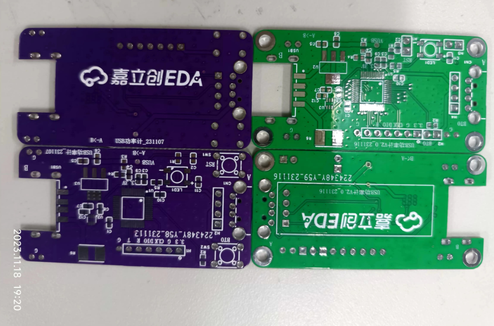
The hardware for the second board has arrived, but I won't have time to finish it before the deadline. There's still room for improvement in both software and hardware. Anyone interested can join me in DIY.
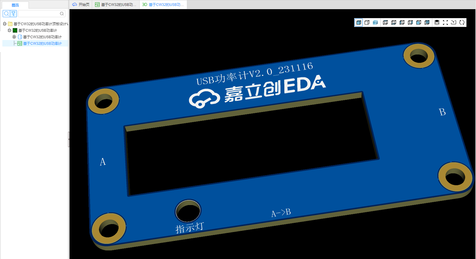
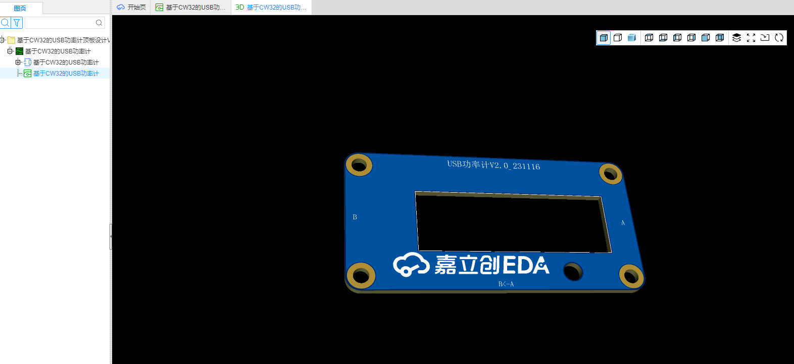
Making a PCB cover directly for the second version should yield better results. Why not print a shell? That's obvious, we're just too poor!
The PCB cover hasn't arrived yet, but here are some preview images on Bilibili: [
Links to Bilibili videos] (https://www.bilibili.com/video/BV1T94y1H7KJ/?pop_share=1&vd_source=e36622a05269c0356d6cd566056a2488 ) [Links to Bilibili videos]( https://www.bilibili.com/video/BV1MH4y1q7Wp/?pop_share=1&vd_source=e36622a05269c0356d6cd566056a2488 ) [Links to Bilibili videos] (https://www.bilibili.com/video/BV1MH4y1q7Wp/?pop_share=1&vd_source=e36622a05269c0356d6cd566056a2488 ) [Links to Bilibili videos] (https://www.bilibili.com/video/BV1La4y1U74q/?pop_share=1&vd_source=e36622a05269c0356d6cd566056a2488 )


 京公网安备 11010802033920号

 225MPW250K


