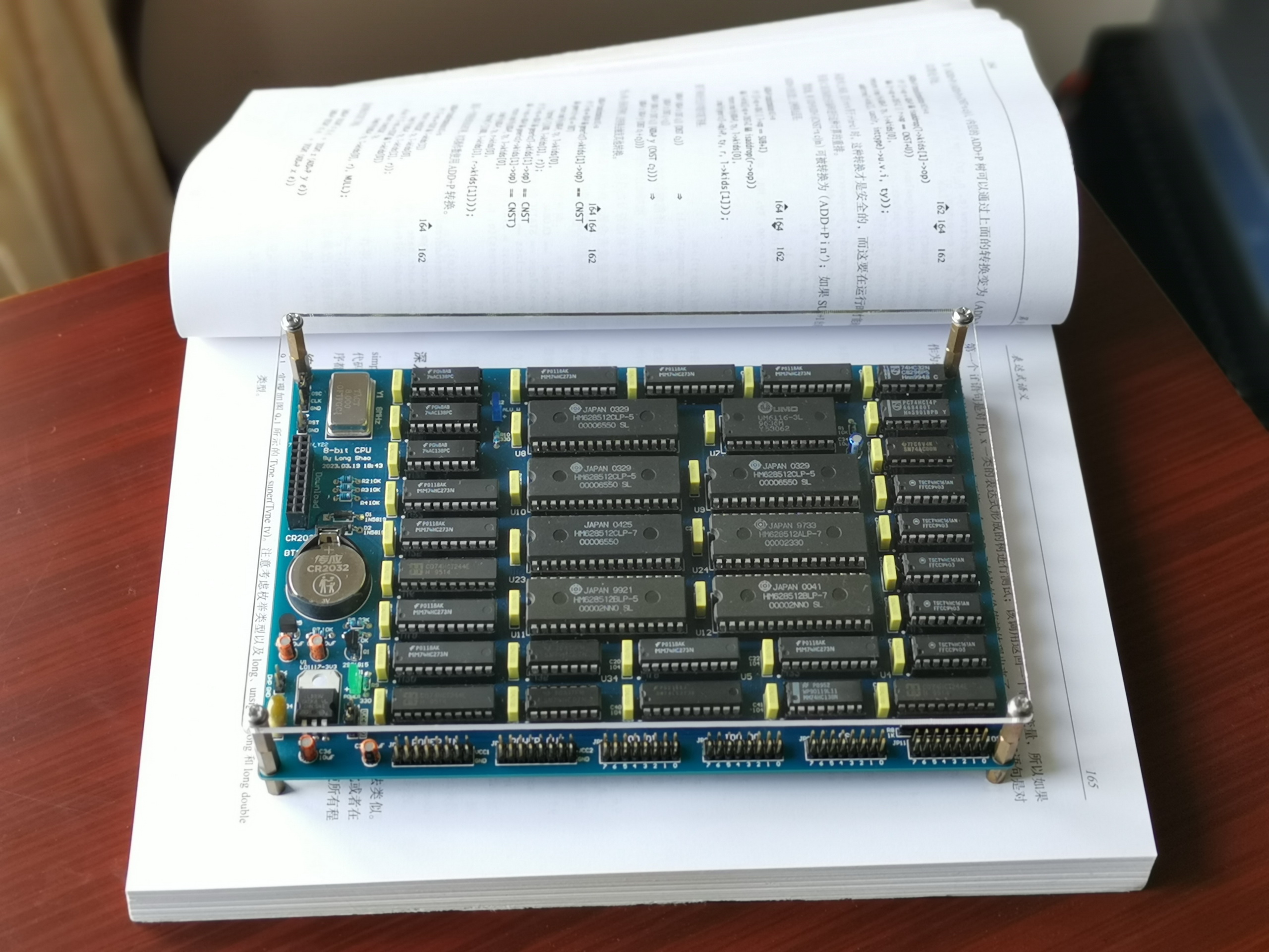
This is a Longshao CPU-74HC logic gate direct plug-in version - LCEDA version, convenient for those without AD to view and replicate. Video: https://www.bilibili.com/video/BV1Pp4y1F7ix
Data: Link: https://pan.baidu.com/s/1n2U553-tAYNSQ06JEb88gA Extraction code: 7777
Clock speed: 8MHz
ROM: 1MB
RAM: 1MB
The main component models and quantities required are as follows:
74AC00
1
74HC00
1
74HC07
2
74HC08
1
74HC14
2
74HC32
2
74HC74
2
74AC138
3
74HC138
1
74HC595
2
74HC161
8
74HC273
9
74LS273
1
74HCT244
3


PDF_Long Shao CPU - 10th Anniversary Collector's Edition - LCEDA Professional Edition.zip
Altium_Longshao CPU - 10th Anniversary Collector's Edition - LCEDA Professional Edition.zip
PADS_Longshao CPU-10th Anniversary Collector's Edition-LCEDA Professional Edition.zip
BOM_Longshao CPU - 10th Anniversary Collector's Edition - LCEDA Professional Edition.xlsx
91461
Controlled sounding rocket - flight control
A low-cost, modular, controlled sounding rocket concept based on the Arduino nano. Only the engine's airtightness was verified; the quarter-load test did not produce effective thrust, and this is for reference only.
The following key points are highlighted
in red for warning purposes.
**Disclaimer:** Model rockets carry inherent risks. Readers attempting to build, test, or launch the engines mentioned in this project should be fully aware of the risks, choose a safe location, and take adequate protective measures. For details, please refer to the attached "Chinese Amateur Rocket Execution Standards." This article represents the author's personal views only; readers are solely responsible for any consequences. The author and LCSC open-source hardware platform bear no responsibility for any losses incurred. If you fully understand and agree to the above disclaimer, please continue reading. **Modular Reusable Sounding
Rocket Based on Arduino Nano Flight Controller**
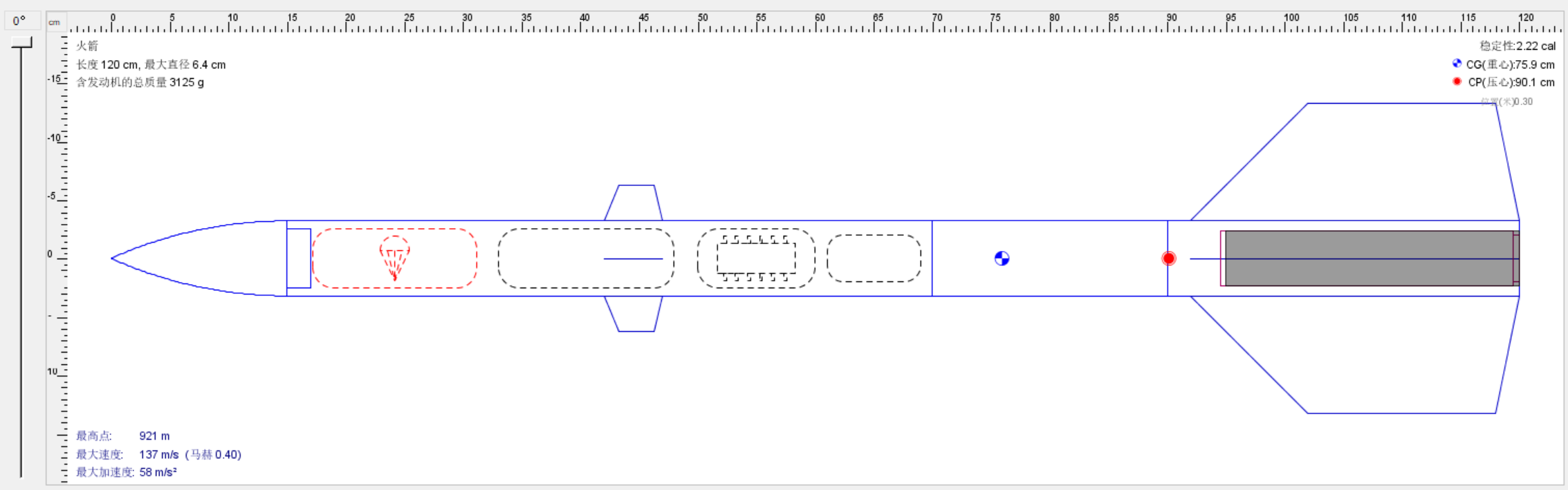
**Aerodynamics:** The rocket body has a canard configuration, with a stability of 2.22 cal based on OpenRocket simulation results. **
Flight Controller:** The Arduino development board collects real-time attitude, position, displacement, velocity, and acceleration information from the combined JY61P attitude sensor and WTGPS-300 navigation module via serial port. It calculates the error between the current attitude and the ideal attitude, then uses a PID algorithm (proportional integration differentiation) to determine the angle to which the four servos should rotate and sends the results (see the attached Arduino flight controller example for details).
Recovery: Provides a parachute opening signal output port, led out from the microcontroller's D6 pin. The input and output are inverted. For pyrotechnic parachute opening, connect to the ignition head; for mechanical parachute opening, connect to a relay and a push-pull electromagnet (requires a freewheeling diode).
Engine: The engine specification is 46-25, i.e., 46mm outer diameter and 25cm length. The engine casing is made of 3mm thick, 46mm outer diameter, 40mm inner diameter, and 250mm long 6061 aluminum alloy tubing. The propellant grain's outer heat insulation layer is 1.8mm thick, 39.6mm outer diameter, 36mm inner diameter, and 200mm long 3K carbon fiber tubing. The nozzle and plug are made of 6061 aluminum alloy. Its fuel is the well-established KNSB (65% KNO3 + 35% sorbitol, C6H14O6 by mass) solid engine fuel, which works well under low pressure. This propellant grain can be cast and processed, making it safer than KNDX fuel (KNO3 + C6H12O6). The nozzle inner wall is coated with heat-insulating paint. Ideally, the chemical equation is as follows: 26KNO3 + 5C6H14O6 ==ignition== 13K2CO3 + 17CO2↑ + 35H2O↑ + 13N2↑. In reality, combustion produces a small amount of nitrogen oxides. For precautions regarding the engine, please refer to the attached "Chinese Amateur Rocket Execution Standards".
Simulation diagram.
Software used: Solidworks Flow Simulation 2022. I'm unsure if Solidworks Flow Simulation can perform fluid simulations in semi-open spaces, or if it only supports one inlet and one outlet. Therefore, I opted for a less ideal solution: having the nozzle inject gas into a cylindrical tube with a radius of 1 meter (which can be considered an open space).

Partial fluid simulation (angle of attack 10°, incoming flow velocity 50m/s).

Hardware introduction:
The main control board and sensor board are separate; the main controller is an ATMega328P-AU.
For further development, refer to
the relevant functions in the arduino.cc project
. A reference scheme for a sounding rocket. The flight control board can collect its own attitude, acceleration, velocity*, altitude*, position*, and displacement* information, and transmit it back in real time via a remote serial port. Functions marked with * require GNSS.
Project attributes:
This project is being publicly disclosed for the first time and is my original work. This project has not won any awards in other competitions.
Project progress
: January 28, 2023: The remaining engine, flight control board testing, flight control cabin of the rocket body, and overall rocket joint debugging are incomplete. The remaining parts of the rocket body, fluid simulation, and flight control board design are complete.
April 12, 2023: Open combustion of engine fuel is complete. Most of the component parts on the flight controller board were replaced with patch material, and the current version of the flight controller board has completed testing. The entire rocket casing is complete. Engine testing is underway, but overall rocket debugging is not yet complete. The HX711-based test stand is now complete, and for the first time, the wireless serial port used on the flight controller has been installed on the test stand, enabling remote ignition control. Testing can be conducted without approaching danger zones, significantly improving test safety.
September 28, 2023: Engine development was suspended due to repeated failures to resolve heat insulation and thrust issues during testing.
DIY Guide
Parts List:
I. No-Gear Cabin Version (Demo Version)
1. M5*15 hollow aluminum alloy socket head cap screws. 2.
M2*5 socket head cap screws. 3.
Four M2*12 screws
. 4. Four M2*15 copper pillars.
5. Four M2 nuts.
6. One Witt Intelligent JY60 attitude sensor module. //You should be able to buy this for under 80 RMB, which is much more cost-effective than the FDISystem Deta10 which costs several hundred RMB.
7. (Optional, requires custom programming) One GPS module using the UART protocol.
8. Zhengdian Atom ATK-LORA-01 module.
9. Four MG90S servos. //Metal gears are more reliable.
10. A 1.5m~2m diameter parachute with a cord.
11. Engine 6061 aluminum alloy casing, see attached sldprt for details.
12. Engine carbon fiber heat insulation tube, inner diameter 36mm, outer diameter 39.8mm, length 200mm.
13. Engine nozzle and plug, listed in the sldprt file, requires high-temperature resistant material processing.
14. Four engine fluororubber seals, 38mm or 40mm outer diameter, 3.5mm diameter.
15. Two engine stainless steel retaining rings, 40mm hole stop.
16. Two engine copper gaskets, see attachment for details.
17. 65-35 ratio cast KNSB fuel. //Safety first, no open flames, no heating above 200 degrees Celsius.
18. Rocket-mounted camera; any action camera of this size will do. Smaller cameras will require a custom-made housing. Link: High-definition action camera, snorkeling, waterproof, underwater digital camera, travel, cycling, motorcycle helmet, dashcam - Taobao (taobao.com)
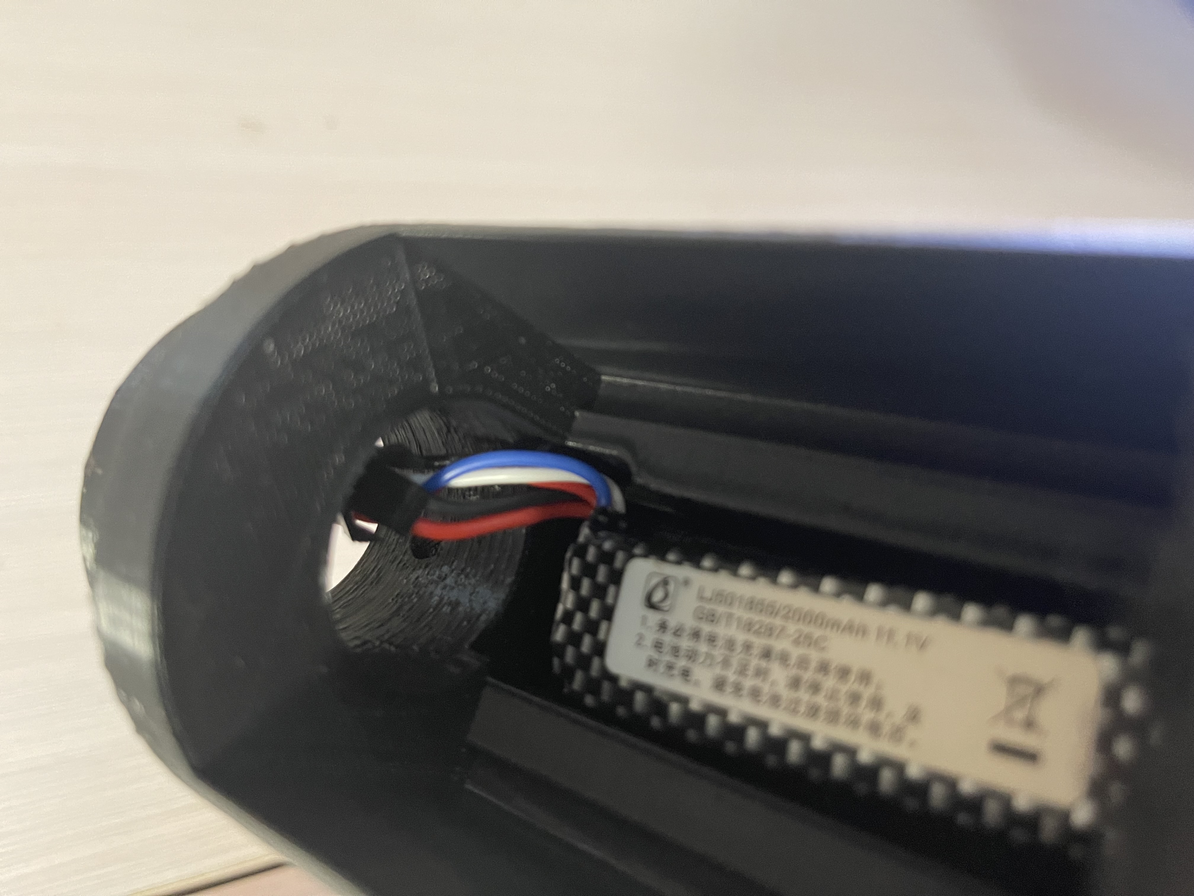
19. 11.1 volt or slightly higher battery.
20. 3D printed model; infill ratio should be fine-tuned according to your load and engine thrust, do not fill 100%.
1. Download the compressed STL file in the attachment and unzip it. Use slicing software (such as Cura, Prusa, JGcreate) to slice and convert to gcode, then use a 3D printer to print each compartment. The sliced gcode can be directly used with an FDM 3D printer (Fused Deposition Modeling printer). PLA filament can be used, with a heated bed temperature of 50 degrees Celsius and a printhead temperature set between 190 and 210 degrees Celsius. Printers using UV-cured resin cannot be used for printing rockets; UV-cured resin is brittle, and UV-curing machines cannot use the gcode files of FDM printers—the two are incompatible. Note that printed PLA models must be sealed and stored to prevent oxidation, as oxidized models become extremely brittle. This project will use approximately two rolls of filament.
2. PCB prototyping and soldering.
3. Burning the bootloader and flight controller program. You will need to purchase an Arduino Nano and a matching USB cable; the total price should generally not exceed 30 yuan.
Download the editor: https://www.arduino.cc/en/software.
Download "JY901" from the attachment, unzip it, and copy it to the Arduino's libraries folder. If the JY901 function library is missing, the program will report an error. If you are using a newer version of the IDE and cannot find the libraries, please open the editor and add the library file directly in Project -- Load Library -- Add ZIP Library.
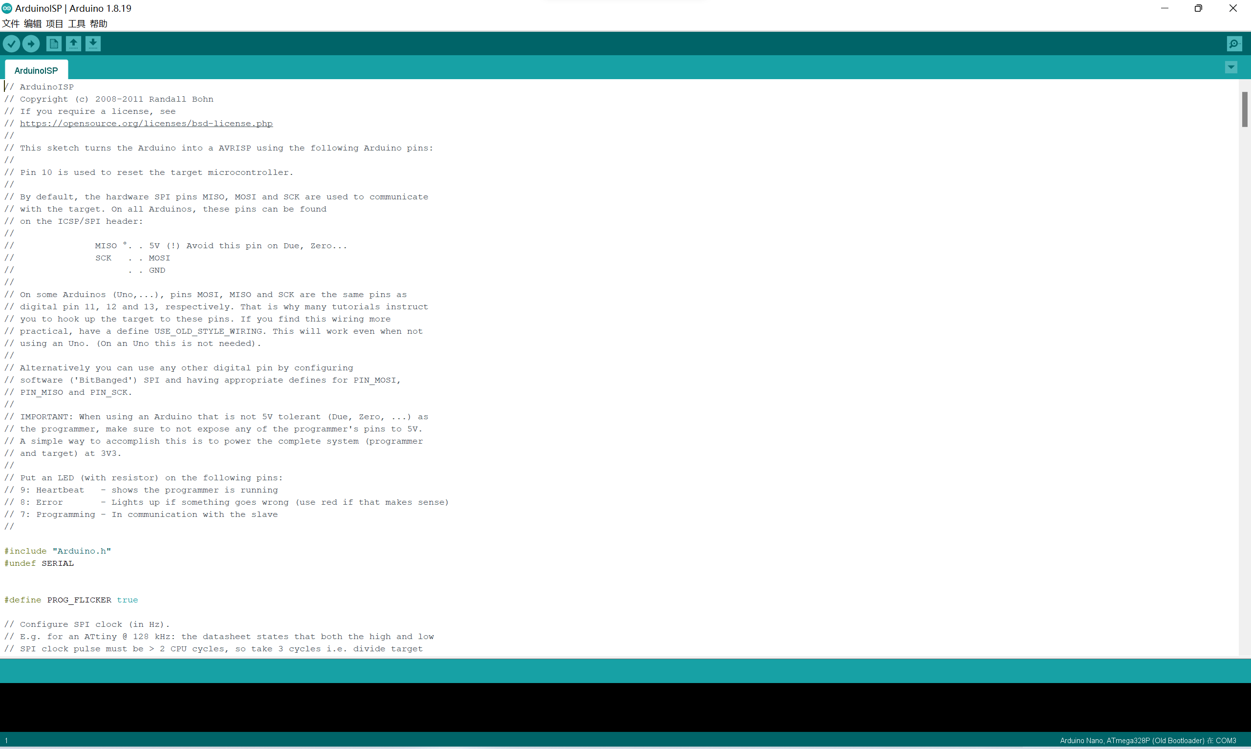
Then take out the main control board you just soldered (only the main control board is needed; do not connect the sensor board), and we will begin wiring. The 6-pin header on top is where you will connect next. This burning method is generally called ICSP, or In-Circuit Serial Programming. After soldering the main control board (GND GND +5V +5V MISO MISO MOSI MOSI D10 RESET SCK SCK)
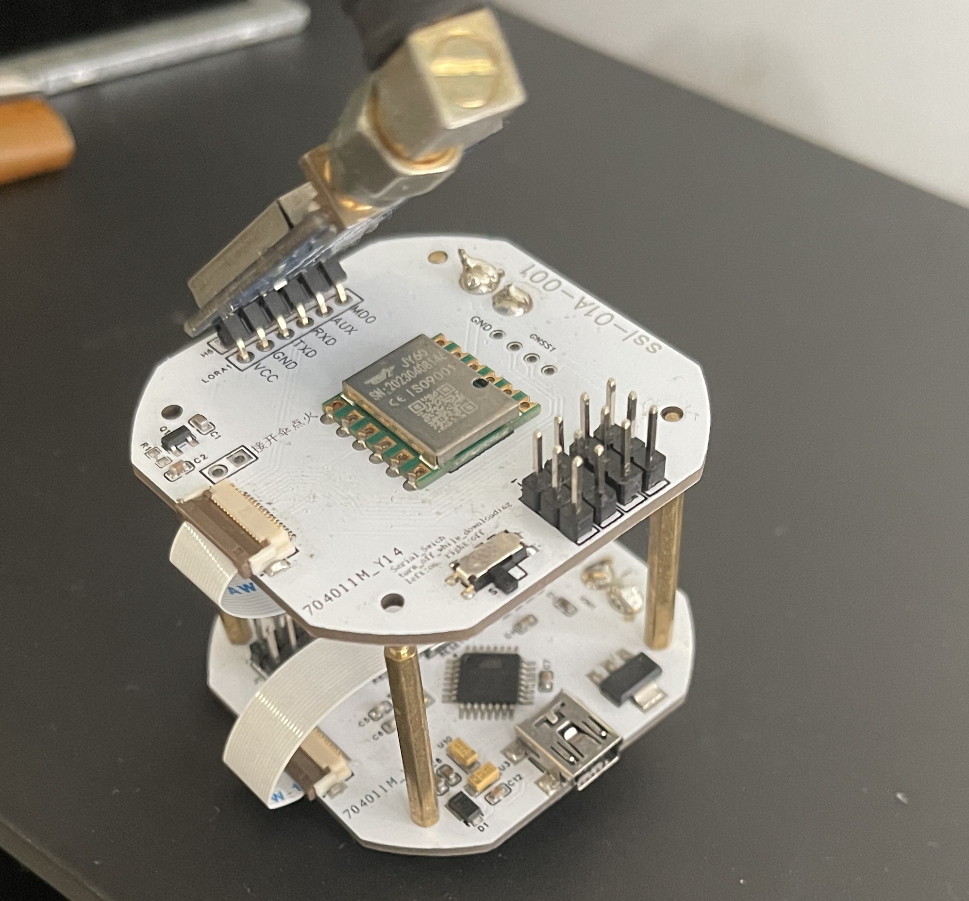
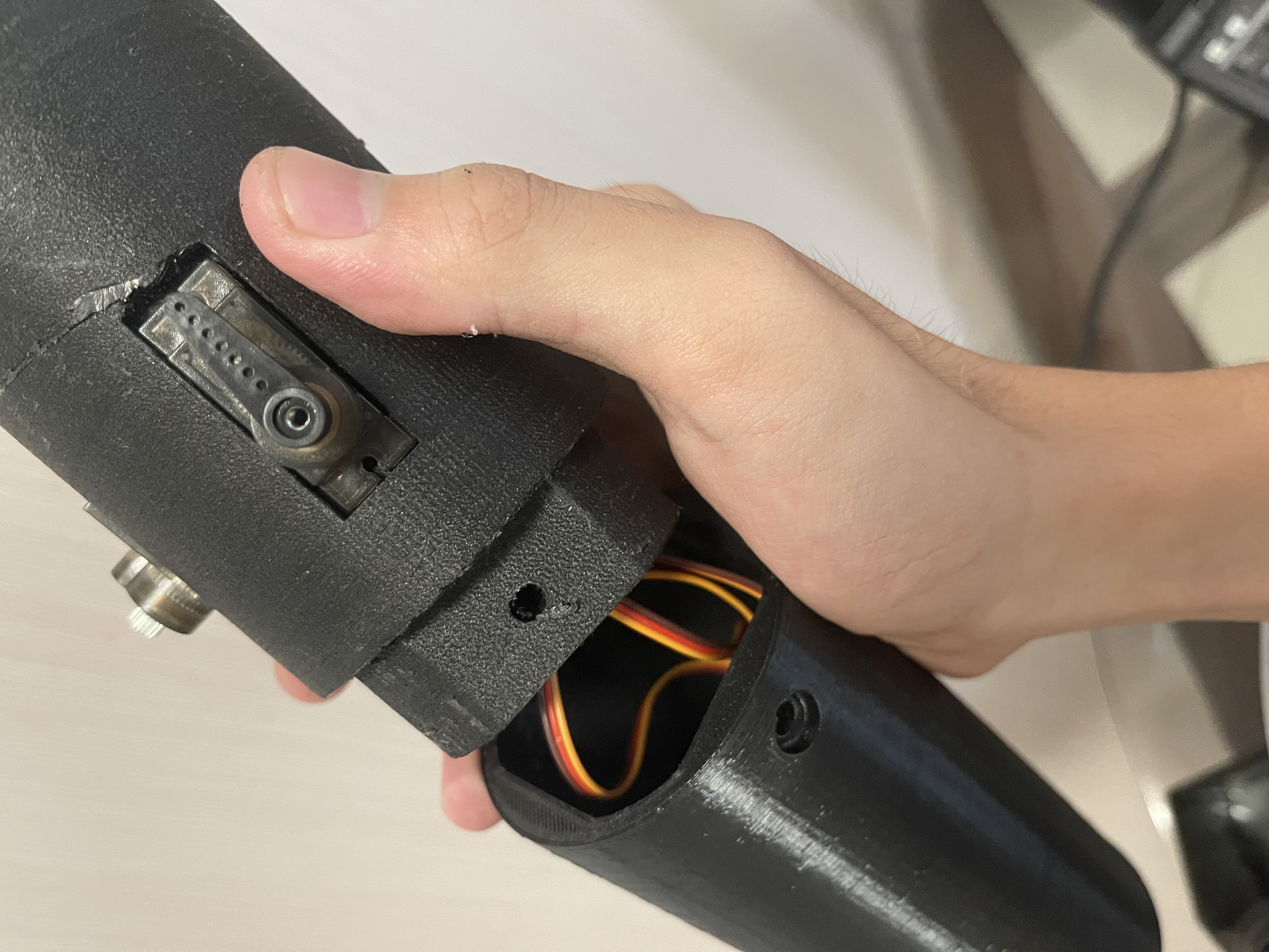
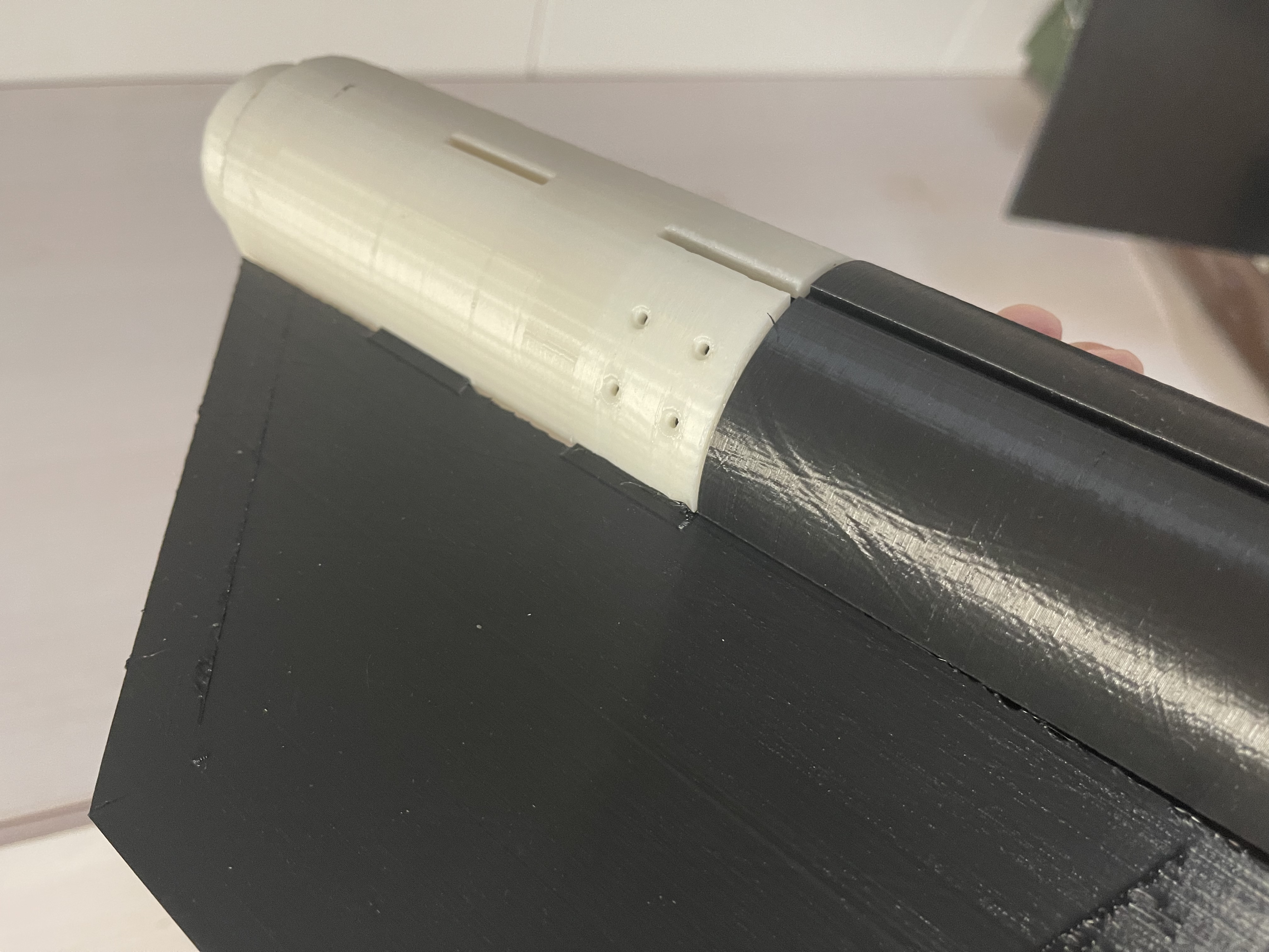
on the Arduino Nano you purchased separately , do not disconnect the connection between the two boards. Connect the Arduino Nano to your computer using a USB cable and check in Device Manager. Your computer should recognize it. If not, install and run the attached "CH341SER.EXE" to install the driver. Open the editor, click File -- Examples -- ArduinoISP. If this window appears on your screen, it means you are doing it correctly. Burn this program to the Arduino Nano you purchased separately. This time, select AVRISP mkII as the programmer. Next, click "Tools," select the correct development board, and the port your development board is connected to. For this flight controller, select as shown in the picture, and select Arduino as ISP as the programmer. Note that you are selecting the development board information of the chip to be burned into the bootloader, not the Arduino Nano you purchased separately. However, in this project, the information of both boards is Arduino Nano (Old Bootloader). Click "Burn Boot Program". After successful burning, you can disconnect the wires between the two boards, connect the flight controller board with a USB cable, and switch the programmer back to AVRISP mkII to burn the flight controller program. This time it's much simpler; just open the flight controller program and click the small arrow in the upper left corner of the screen. 4. Install the electrical system. You need to buy four MG90S metal gear servos, costing approximately 50 yuan. Glue will be used to install the servos. Take four stickers and attach X+, X-, Y+, and Y- to the ribbon cables of the four servos respectively. Install the servos according to the top view below. Place the FPC sockets of the sensor board and main control board on your left, with the side with components facing up. Install the sensor board on top of the main control board and connect the wires. When connecting the upper and lower boards of the flight controller, please be sure to use a reverse 16-pin FPC ribbon cable (i.e., when the ribbon cable is laid flat on the table, the solder fingers at both ends are not on the same side), otherwise the entire flight controller will not work properly. Please check before connecting. The two boards are secured with four M2 copper pillars, which also serve as 5V power supplies. The protruding end of the pillar faces upwards, and the concave end faces downwards; screws will be tightened under the PCB later. The assembled flight controller is then inserted into the electrical components bay. M2 screw holes are pre-drilled in the bottom of the bay, and four M2 socket head cap screws (12mm in length) are used for securing it. Finally, the tenons and mortises are aligned, the two bays are connected, and M5 screws are tightened. The tenons and mortises are designed to prevent incorrect assembly; the two bays will not fit together if connected incorrectly. (If you are a little confused, please refer to the pictures and steps below.) The actual flight controller board is shown. Due to limited space in the bay, without using an antenna extension cable, the module can only be inserted into the bay in this very abstract way. Above: Camera/Battery Bay . Above: Connection between the electrical components bay and the servo bay. Assembly of the tail fin and engine bay. The white cover represents the discarded first version model. The second version model (black, with significant changes from the first version) has several parts currently being printed; the cover will be replaced after printing. Image reference : pinout.png Source: arduino.cc Image: Module and MCU connection Source: https://wit-motion.yuque.com/wumwnr/docs/geusnl?#%20%E3%80%8AJY60%E4%BA%A7%E5%93%81%E8%A7%84%E6%A0%BC%E4%B9%A6%E3%80%8B Library file ServoTimer2: Project directory preview - servotimer2 - GitCode Library file JY901: Wit Intelligent - Focused on attitude sensors (wit-motion.cn ) I do not own the copyright to these materials. Please contact me to delete them if there are any copyright issues. Open source license This project, except for the cited literature/images, is licensed under GPL3.0 open source. Closed-source commercial release is prohibited. Please indicate the source when reprinting; no notification is required. Postscript My skill level is limited. My sensor board uses only finished modules. Due to academic reasons, the project will not be further developed. Two important points : First, the ATK-Lora-01 module does not immediately transmit received data. It first stores it in a buffer. The RF chip will only start transmitting when the buffer reaches 58 bytes. New data can be added during transmission. When the buffer is less than 58 bytes, the module will wait for one byte. If no input is received, the data transmission will be considered complete. This means that the length of each data set is variable, which can easily lead to reverse ordering, missing frames, etc., when inputting fragmented data. Please be careful. Second, using the Arduino Nano's Timer1 timer simultaneously with the SoftwareSerial and Servo libraries will cause servo motor jitter. Please install the attached ServoTimer2 library.


Chinese Amateur Rocket Execution Standards.pdf
CH341SER.EXE
Casing sldprt.7z
ServoTimer2.zip
arduino20231015.zip
JY901.zip
PDF_Controlled Sounding Rocket - Flight Control.zip
Altium_Controlled Sounding Rocket-Flight Control.zip
PADS_Controlled Sounding Rocket - Flight Control.zip
BOM_Controlled Sounding Rocket - Flight Control.xlsx
91462
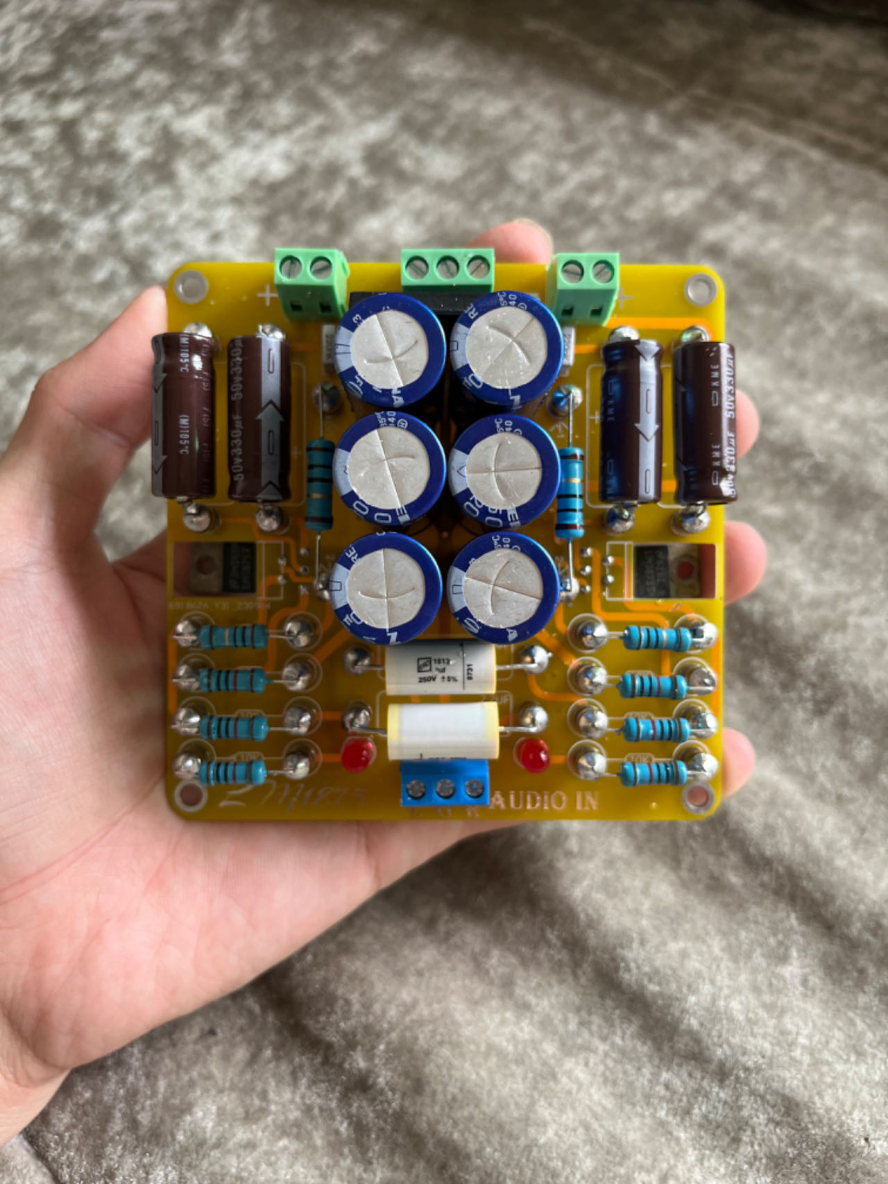
GC version LM1875 power amplifier
LM1875 power amplifier board designed using GC circuitry
Introduction: This is a board designed based on the GC circuitry. While arranging the layout, I unexpectedly thought of adding point-to-point (PTP) pins.
Regarding the schematic and board: Because some components were designed by myself, the model isn't visible in the 3D preview. I'm a student, just starting my second year of high school, so I might not be able to reply to comments immediately, but I will answer every question. Since I've open-sourced it, I'm responsible for any problems others encounter during their DIY process. Any better suggestions are welcome. The schematic might not be the most aesthetically pleasing... but the board has been received and tested, so please use it with confidence (doge).
First, it's important to note that almost all the pads on this board require PTP pins to be screwed on first; components cannot be soldered directly. The pads requiring PTP pins are all 3mm in diameter.
You can find PTP pins by searching "PTP pins" on Taobao. Some are quite expensive (around 1 RMB each), the cheapest I found was 0.25 RMB each, although not as aesthetically pleasing as the more expensive ones. This picture shows a 0.25 each capacitor

; of course, you can buy others as well, as long as the diameter is 3mm. A total of 32 leveling screws are needed, so keep an eye on your wallet.
/************************************************* Regarding component selection ******************************************/
1. The filter capacitors on the board are compatible with 13mm and 16mm diameter capacitors. Just pay attention to this when purchasing. It's best not to buy too high a size, as it doesn't look good.
2. Input coupling capacitors are generally 2.2uf, but you can increase or decrease them depending on your preference. Just don't make them too big.
3. Decoupling capacitors can range from 22uf to 1000uf.
4. Basically, just don't make the components too big.
5. Be mindful of your budget.
/***********************Regarding cost*********************/
There isn't a precise figure. It depends on the components used. If you're using a free board (e.g., JLCPCB YYDS) and using lower-quality components, the cost will be around 50-60 (excluding heatsinks and transformers).
With better components, it could cost anywhere from 100 to over 100. It's not recommended to buy expensive mounting pins, as they can add up significantly to the cost. Generally, 70-80 watts is enough to make the board (excluding heatsink and transformer chassis).
/*Soldering Precautions*/
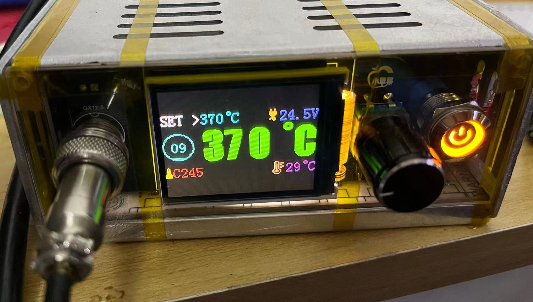
When soldering, set the soldering iron temperature high and don't use too low a wattage.
Please ensure good ventilation during soldering, as the smell will be strong. Also, pay attention to residual heat, especially on the jumper pins (don't ask me how I know).
If the jumper pins aren't tight, you can solder them securely. You can also buy those that don't require screws for direct soldering.
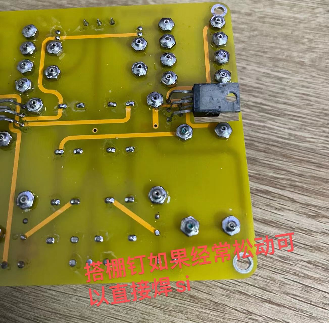
Also, when soldering the 1875, be careful not to bridging the leads or leaving any gaps in the solder.
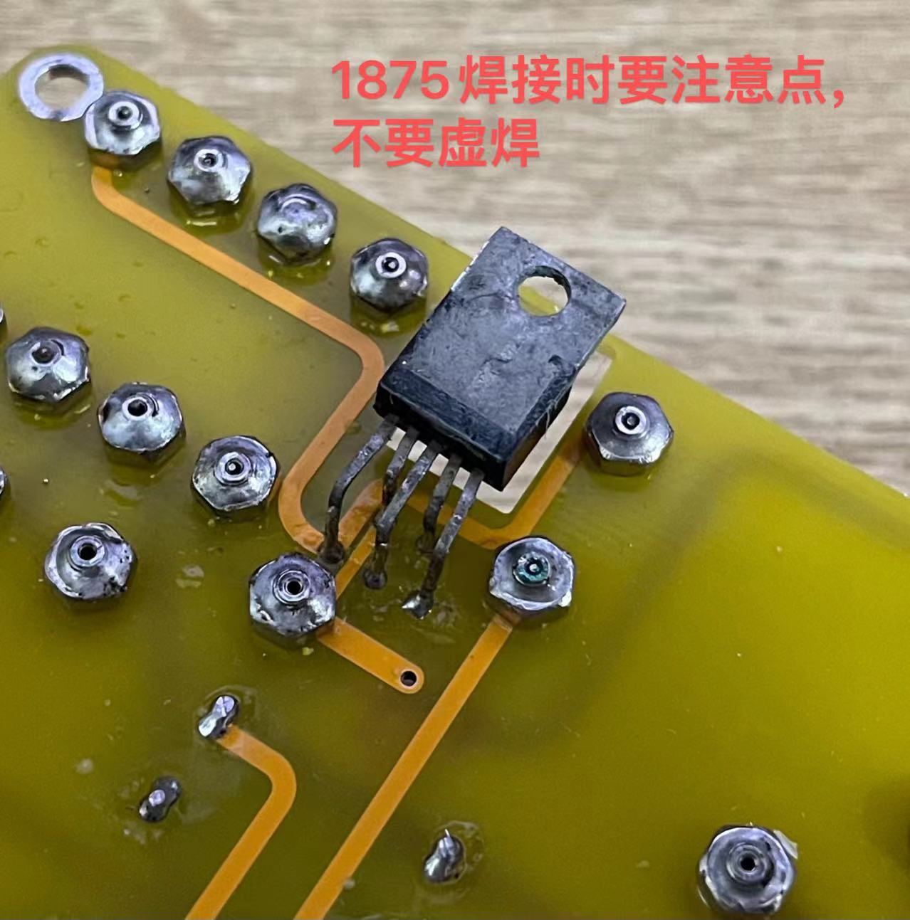
A very important point when soldering the 1875 is to raise the leads high! If they are too low, the jumper pins will touch the heatsink. This is extremely important!!!

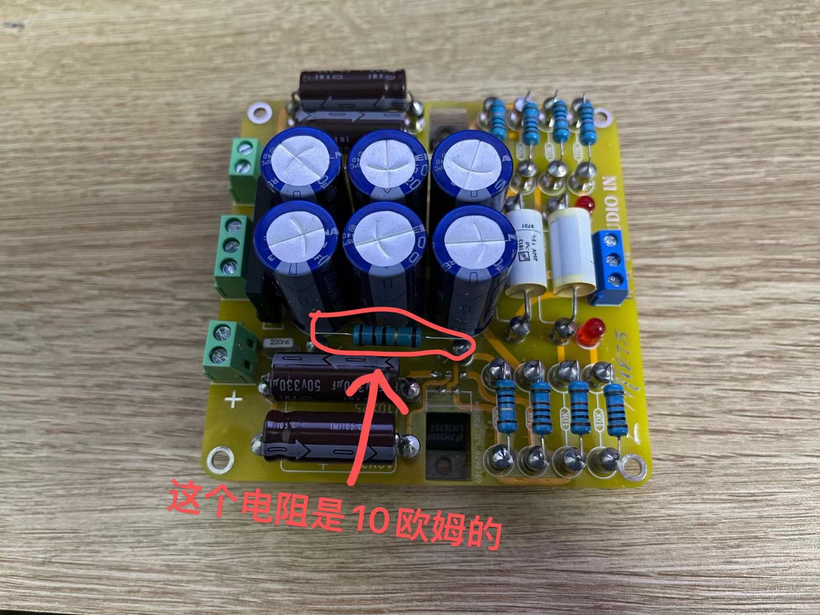
Another point is that the enclosed resistor is actually 10 ohms.
/************************************************************ Final Stage: Check and Power-On Test *****************************************************/
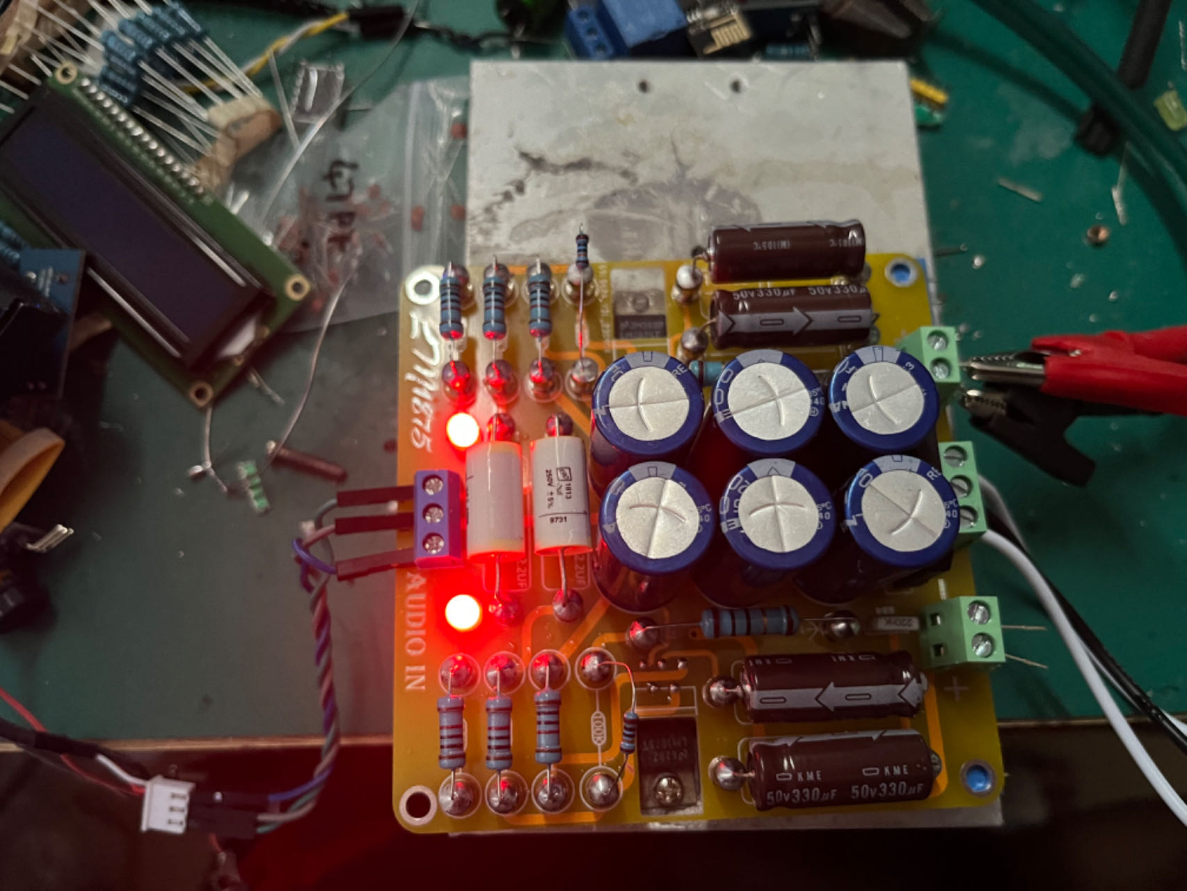
After the components are soldered correctly without any missing solder joints, you can proceed with the power-on test. If possible, use a low-voltage transformer for the test, and remember to install a heatsink.
@@@@@@@@@@@ After powering on, do not connect the speaker or audio input yet, just connect the transformer. After powering on, both power indicator lights will light up. If this is OK, there should
be no problems.
@@@@@@@@@@@ Then connect the speaker and power it on. The speaker should have no hum or background noise at this point. Then touch the "L" or "R" pin on the audio input.
The speaker should make a "hissing" sound when touched (this is hard to describe, but if you hear a sound, that's correct). Test both channels. If this passes, it means there are basically no problems, and you can
connect speakers to test it. Also, pay attention to whether there is any hum or background noise. There shouldn't be any background noise. When I tested it, I could barely hear it unless I put my ear right up to the speaker (
I mean, the background noise was almost zero).
When connecting the audio source, I recommend using a Bluetooth module. It's best not to connect devices like mobile phones first.
After passing the test, you can choose to match it with your case or other components.
This is a picture of my final soldered result.
This picture is of the previous version; this board is an improvement on that (the previous version had too thin wiring, haha). Finally, if you find any problems or design flaws in the schematic, PCB, or other aspects, please leave a message to let me know. Thank you. You can also discuss any issues you encounter

during soldering or debugging. October 14, 2023
PDF_GC version of LM1875 power amplifier.zip
Altium_GC version LM1875 power amplifier.zip
PADS_GC version LM1875 power amplifier.zip
BOM_GC version LM1875 power amplifier.xlsx
91463
combat robots
Combat robots built using the Liangshan School development board and bus servo motors.
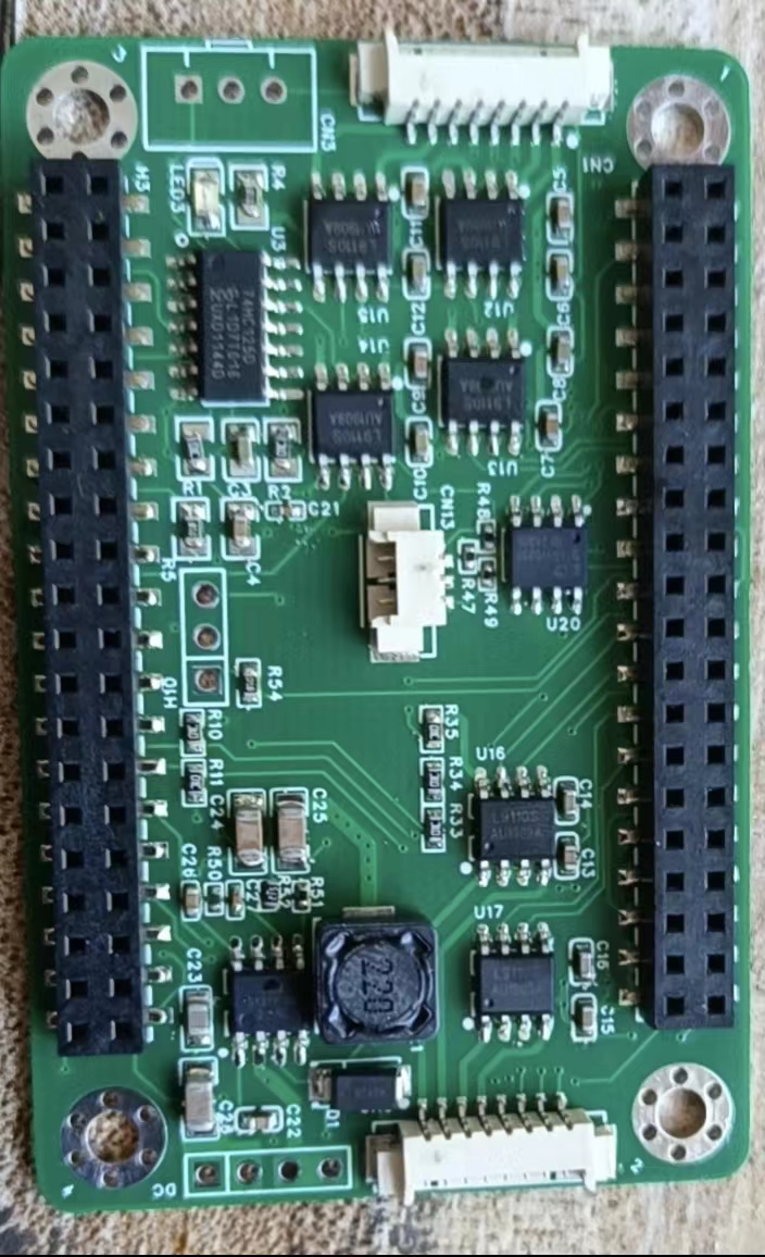
The combat robot's functions are achieved through the combination of various modules. The main control
board (the robot's brain) uses the Liangshanpai development board, with the GD32F470 as its main control chip. The GD32F470 has rich peripherals and a 240MHz clock speed, potentially perfectly supporting the robot's various functions. An expansion board was added to the main control board to allow communication between the components on the main control board and the expansion board. The expansion board diagram is shown below.
The
robot uses 7 modules and 7 drive circuits. These modules include a stepper motor module, a bus servo module, a 0.96-inch OLED module, a MAX7219 dot matrix screen module, an HLK-V2.0 offline interface module, a WS2812 LED, an MPU6050 attitude sensor, a CAN bus circuit, a digital transistor drive circuit, a 5V power supply circuit, a buzzer drive circuit, an ADC battery detection module, a 9G servo drive, and a button detection module. Commonly used modules are not described here, as they are all from the Liangshanpai porting manual, and the programs are also copied from the source code. Let me focus on the parts not mentioned in the manual or that have undergone significant changes in the program:
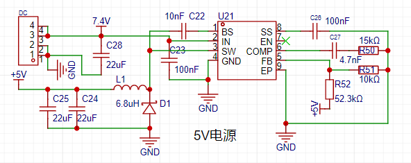
1. Power Supply:
The power supply is the core of the robot. Without sufficient power, the robot cannot move. The 25 WS2812 5050 batteries used for the LED lights and dot matrix screen are very power-intensive, with the total current expected to reach around 1A. The SGM6132 power chip from Sanbang Microelectronics, used in the medicine delivery cart in the electronics competition, can reach up to 3A, and the voltage is adjustable. As shown in the diagram,

each module uses a 5V power supply, directly through R1, R2, R3, and C3. The output power voltage is adjusted. The 3.3V is output through the Liangshanpai development board. The power circuit is shown in the diagram.
Two 18650 2000MA batteries are used, powered by a 16A switch to supply the power chip. See the diagram.

2. Bus Servo:
The main component of the robot is the servo motor. A UBTECH bus servo motor from UBTECH was used. This servo motor was a previously purchased second-hand unit; new bus servos are quite expensive. Ten servos were used. Eight were used for the leg joints, and two for weapon lifting. This bus servo used half-duplex serial communication. The Liangshan School (a computer programming language) can also configure the serial port for half-duplex communication, but I haven't done it before, so I don't know if it will work. I'll try it when I have time. For now, I'll use the circuit I've already tested, which will save time and avoid some detours. See the diagram.

The data for this bus servo is in the file below. You can download it if needed. Importantly, this bus servo sends hexadecimal data via serial port. I'll explain the data structure; following this structure will successfully control the servo. You can also refer to my program. The angle reading wasn't implemented; I don't know where the problem is. I'll investigate it later. The data structure is shown in the diagram.
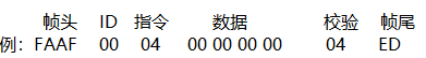
The check bit is the sum of ID + instruction + data.
3. 0.96-inch OLED screen.
The OLED screen circuit is nothing special. The key is that I ported the Arduino U8G2 library to the Liangshan School. This makes it very convenient to call U8G2 library functions. Software I2C driver was used. The LCSC development board's logo and battery level display were implemented using the U8G2 library functions, as demonstrated in the video. I originally wanted to create a cool menu, but didn't have time to debug the program; I'll add the menu items later.
3. MAX7219 Dot Matrix Screen Module:
The dot matrix screen only uses two 37*37 dot matrix panels, mainly displaying the robot's eye expressions.
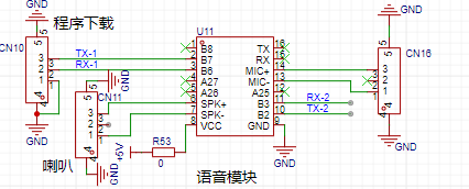
4. Offline Voice Module:
The voice module also uses the Hailink V2.0 module. This voice module is explained in detail in the smart curtain video tutorial. The voice module is quite useful. Five commands were created on the voice module for testing purposes. The circuit diagram is shown in the figure.
Robot Structure Description:
1. Servo Distribution ID Description

; 2. Robot Module Connection IO Table;
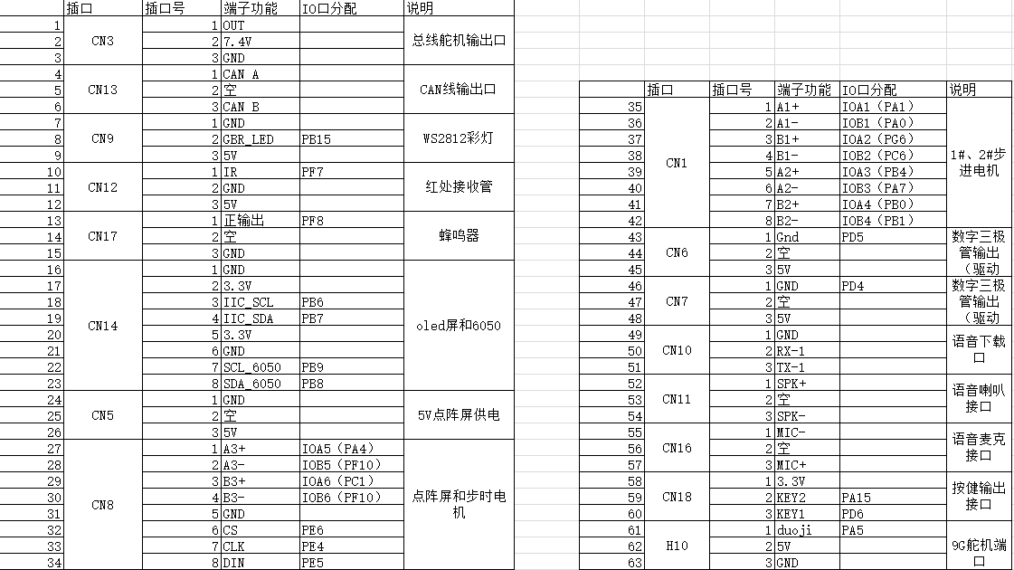
3. Robot Internal Images;
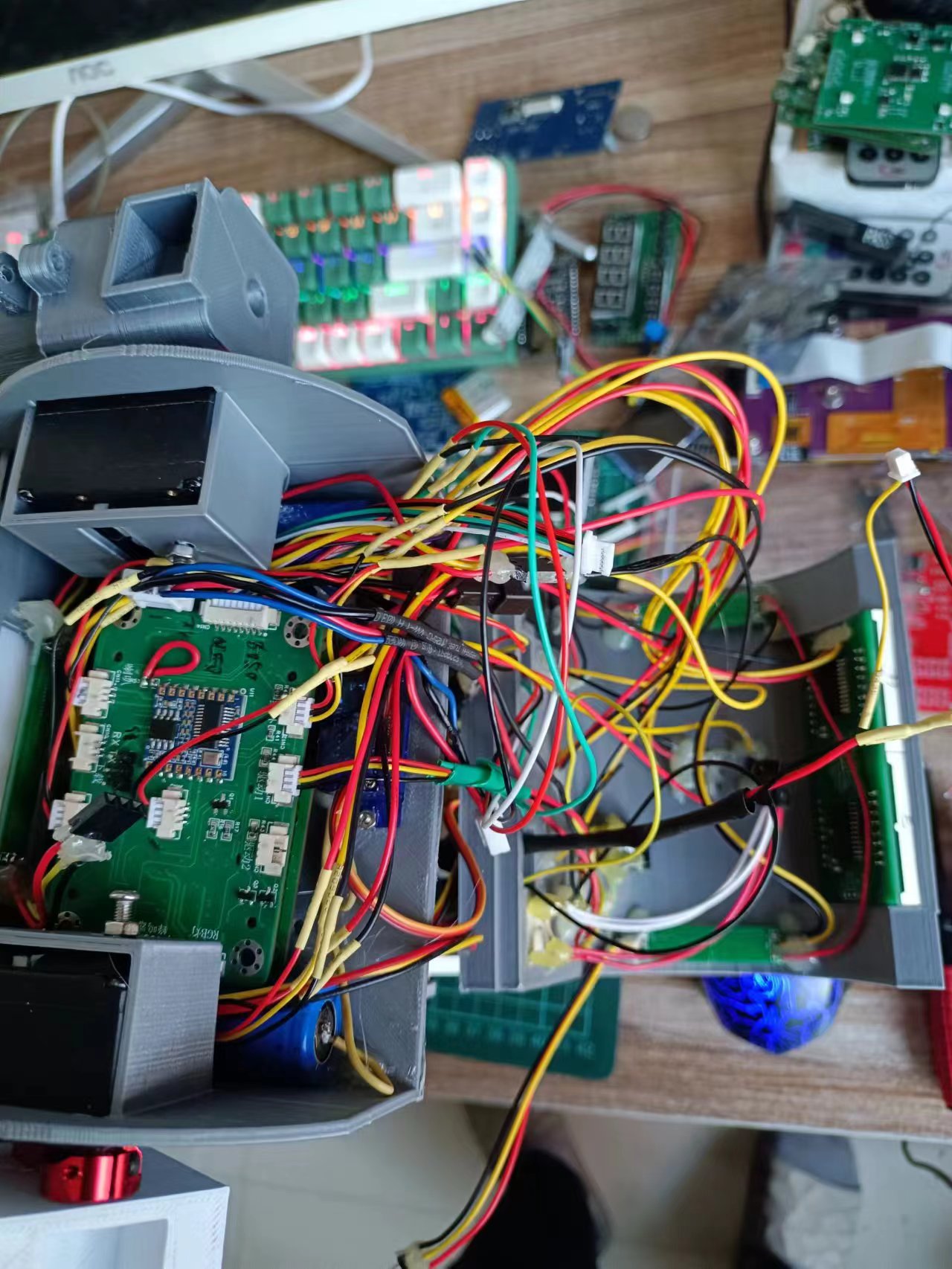
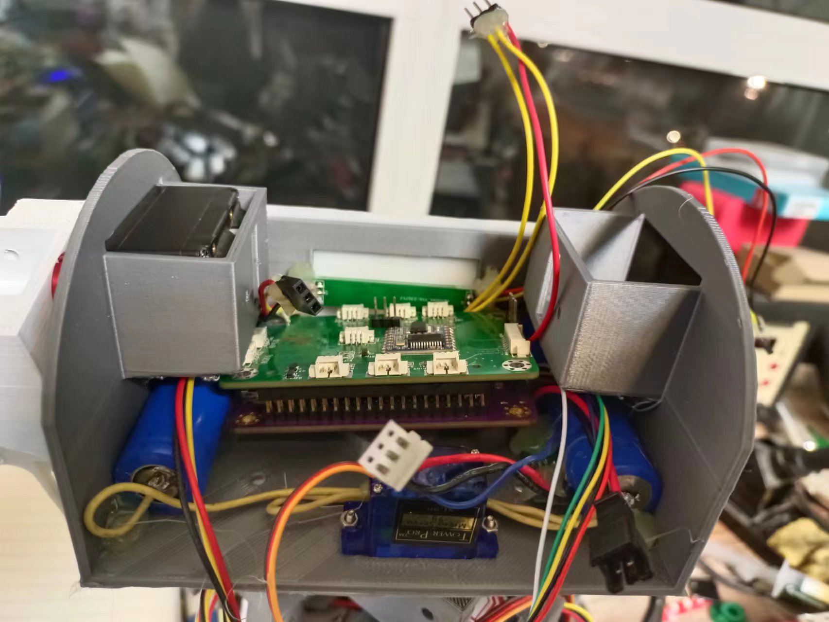
4. Component Positions in the Robot Head;
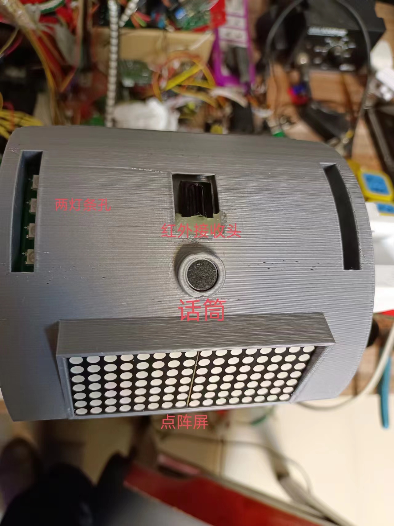

5. Full Robot Image

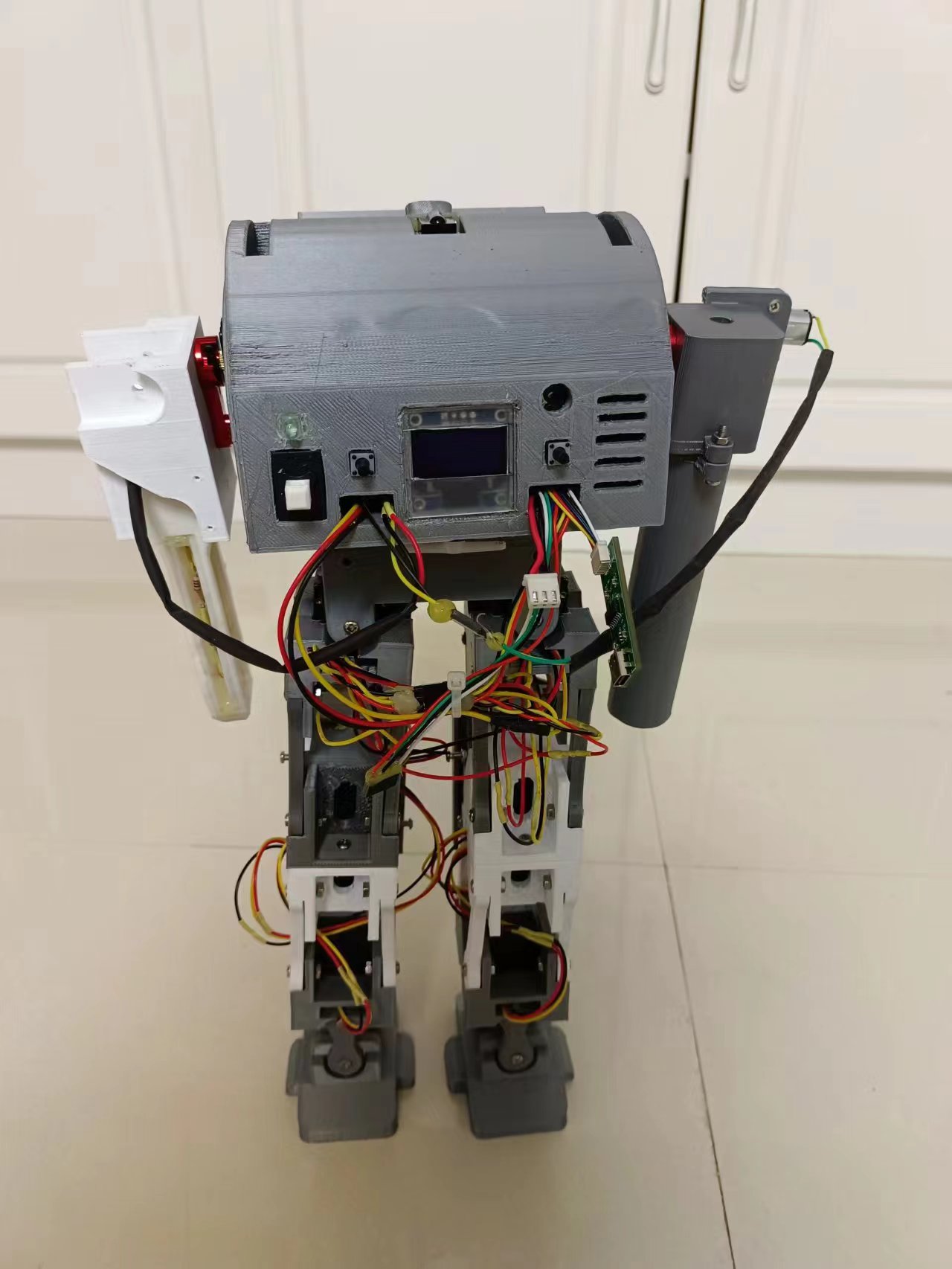
(Bilibili Video Address)
: [Combat Robot, main control uses Liangshanpai development board]. [https://www.bilibili.com/video/BV1VG41127Dq/?share_source=copy_web&vd_source=c4ac3c1e03440fed67ffc76ecb6d23d1](https://www.bilibili.com/video/BV1VG41127Dq/?share_source=copy_web&vd_source=c4ac3c1e03440fed67ffc76ecb6d23d1)
In summary
, bus servos have many advantages in use. Parallel operation saves on wiring and reduces the number of I/O ports required. Speed can also be controlled. Two months were spent completing the 3D model and debugging each module, but the program hasn't been properly debugged yet; the time allotted for program adjustments is too short. The walking posture is still not well-tuned; it's not as easy to adjust as I imagined. Further program updates will be made when time permits.
code.rar
STL file.rar
PDF_Battle Robots.zip
Altium_Battle Robots.zip
PADS_Battle Robots.zip
BOM_Battle Robots.xlsx
91464
AiPi-Eyes-R2_V1.0
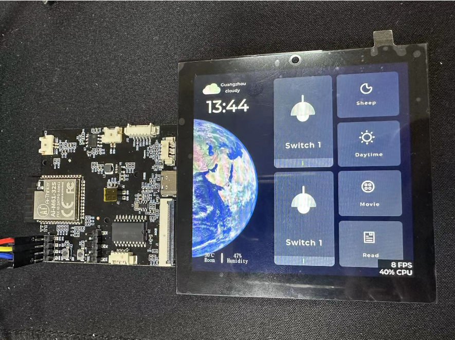
Anxinco Technology 4-inch RGB Interface Display Driver Board
I. Introduction
The R1 isn't the only board capable of directly driving a 4-inch RGB interface display; there's also its smaller version: AiPi-Eyes-R2.
This board has several improvements over the S2:
the DVP camera interface has been removed;
it uses a 4-inch RGB interface display (capacitive touch), with a higher frame rate (maximum 50fps, stable 30fps); and
it's smaller and more refined.
The biggest change is the use of a 4-inch RGB interface display with a resolution of 480*480, and it's smaller than the R1.

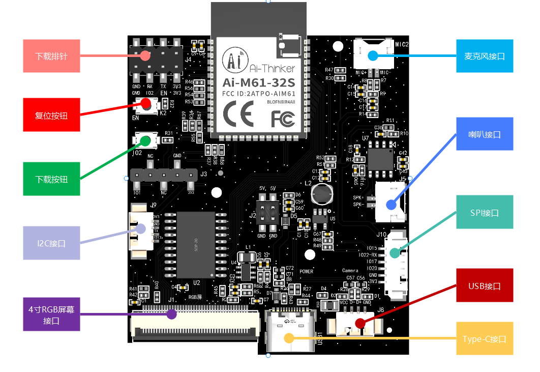
II. Interface Description and System Block Diagram
The R2 is smaller than the R1, but it can also drive a 4-inch RGB interface screen. The difference isn't just in size, but also in the audio chip. The R2 uses the BL618 built-in voice chip for unidirectional audio input and output.
III. RGB Interface Screen Circuit
RGB screens require a significant number of I/O ports; the GPIO of the M61 module alone is far from sufficient. Therefore, latches are needed for GPIO multiplexing.
Thus, the R2 still cannot fully utilize the refresh performance of the RGB screen.

IV. Wiring and Programming:
Compared to the AiPi-Eyes-R1, the R2 features a download header, allowing for programming via TTL connection.

The AiPI-Eyes-R2 is factory encrypted, so a specific boot2 and verification firmware must be specified during operation.
Otherwise, the program may not function correctly.

V. Other
Official Documentation: https://docs.ai-thinker.com/eyes-r
Source Code: https://github.com/Ai-Thinker-Open/AiPi-Open-Kits
PDF_AiPi-Eyes-R2_V1.0.zip
Altium_AiPi-Eyes-R2_V1.0.zip
PADS_AiPi-Eyes-R2_V1.0.zip
BOM_AiPi-Eyes-R2_V1.0.xlsx
91465
4G-OneNet Outdoor Light Acquisition System
This is an outdoor light sensor built using an STM32F103 and a HoloMatic Air724UG 4G module, transmitting light data to the OneNet cloud at second-level intervals.
The
purpose of this project was to create an outdoor light sensor to collect light intensity data from various sensor points in an area. The goal was to predict future light intensity and potential power generation for that area.
This open-source solution for uploading a light sensor to the cloud aims to share how to use the Air724 4G AT module and how to transmit data to the cloud (OneNet) via MQTT. Previously, online resources were scarce and disorganized, and it took me a long time to complete this. The solution also demonstrates how to use relevant APIs to acquire data from the cloud. Python code demonstrating how to use OneNet's HTTPS API to retrieve device data will be provided later.
The overall framework
uses an STM32F103RCT6 as the main controller; the power supply uses an EG1192, a Buck circuit, and also includes a Type-C port, allowing for direct 5V power supply; the 4G module uses a Holtek Air724 4G module; the light sensor uses a MAX44009 module, but here a JT-I2C1208 module was purchased directly, which comes with a waterproof transparent shell and connecting cable; the real-time operating system uses FreeRTOS; the LCD is only used during debugging; the external EEPROM is used to record manually tuned parameters, as the MAX44009 may have offsets requiring manual adjustment. Here, only y = ky'+b is used, where y is the adjusted value and y' is the original value. k and b can be adjusted to improve the offset.
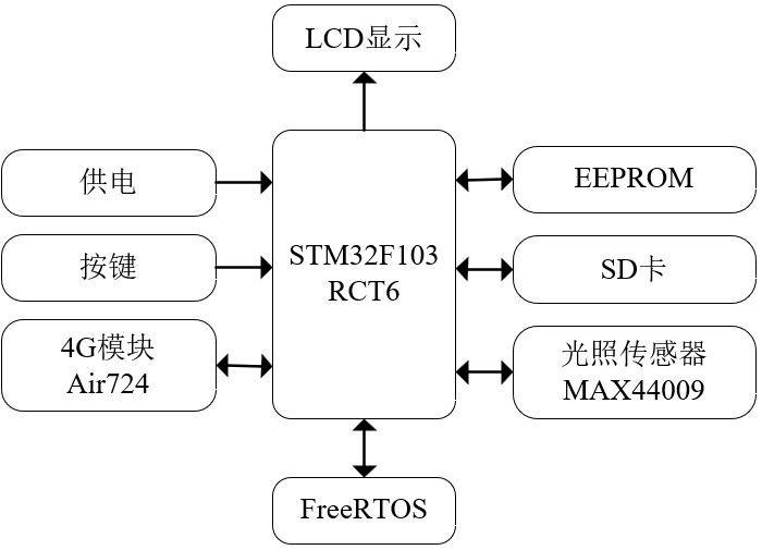
Figure 1 Overall Block Diagram
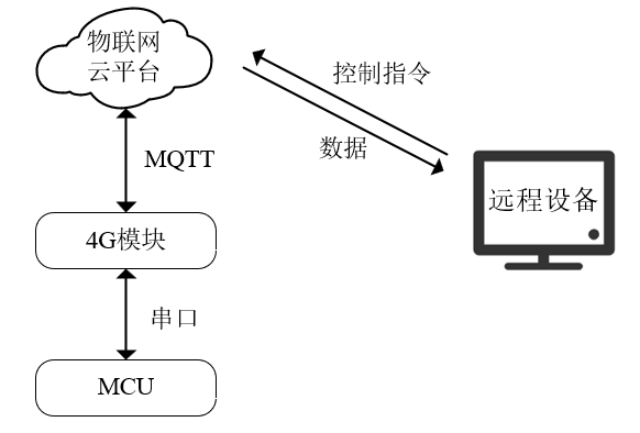
Figure 2 Data Transmission Block Diagram
4G Module Connection to OneNet User Guide
We chose China Mobile's OneNet, purchasing the Air724 4G module from Yinda. Initially, you can connect it to a computer and use a serial port assistant for debugging. We recommend using Gexi Fenghuo Serial Port Assistant. For detailed testing procedures and AT command sets, please refer to the YED M724 AT Firmware User Manual and the Luat 4G LTE Module AT Command Manual. If you want to test the OneNet access device using MQTT.fx, please refer to this link: MQTT.fx Simulating Device Access to IoT Platform. For OneNet access security authentication, please refer to this link: Access Security Authentication.
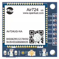
Figure 3 Air724 4G Module
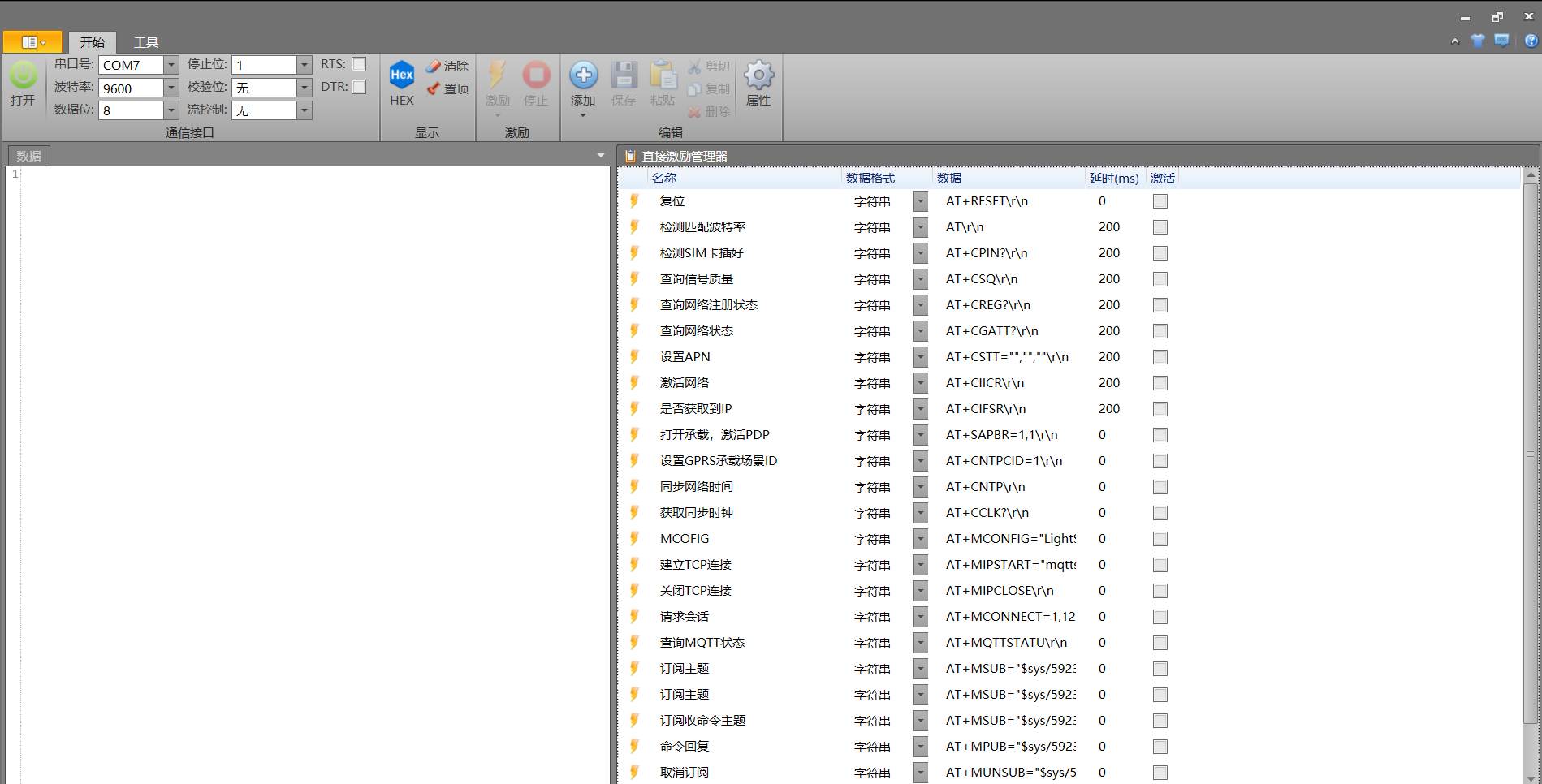
Figure 4 Gexi Fenghuo Interface
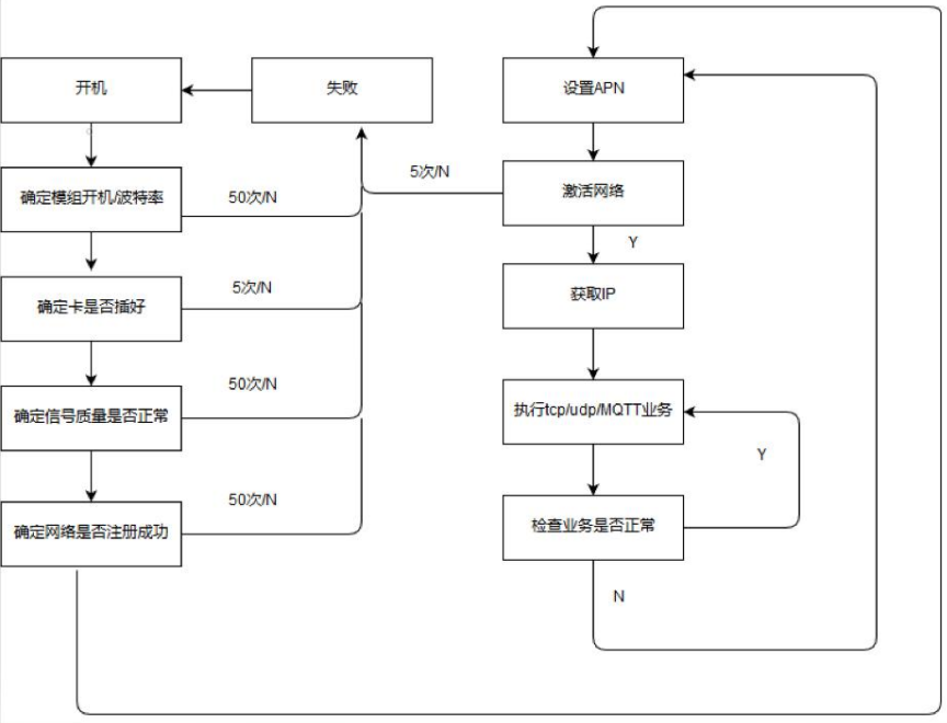
Figure 5 General Internet Access Procedure
The general process of the Air724UG 4G module connecting to OneNet via MQTT is shown in Figure 5, and the specific AT command process it sends is shown in Figure 4. In the specific process analysis, I will only explain the key parts of the sent AT commands. I will not go into detail about the return values; you can find the details in the Luat 4G LTE module AT command manual, code, or the stimulus in Figure 4.
The specific AT command sending process is as follows:
1. Hardware initialization. This includes matching the baud rate, checking if the SIM card is inserted correctly, and using AT+CPIN?
to check if the SIM card is inserted correctly. If it returns +CPIN: READY, it is normal.
2. Network settings. First, check the signal quality; then check the network status, etc. See Figure 4 for details.
3. MCOFIG. The command format is AT+MCONFIG="LightSensor1","592329","version=2018-10-31&res=products%2F592329%2Fdevices%2FLightSensor1&et=1781202267&method=md5&sign=???????????????????"
. The meaning of each position is as follows: "LightSensor1" in the first quotation marks is the name of a device within your product; the second parameter "592329" is your product ID; the third parameter is a token generated according to OneNet requirements, containing the product ID, device name, timestamp "et", encryption method "method", and signature value "sign". The third parameter can be generated using OneNet's token generation tool or the official Python example. The key here needs to be your OneNet product key, not the device key.

Figure 6 shows OneNet's token generation tool
. 4. Establish a TCP connection and request a session. First, establish a TCP connection using the command format AT+MIPSTART="mqtts.heclouds.com",1883
, connecting to port 1883. After sending, a successful connection is indicated by receiving CONNECT OK. Then,
request a session using the command AT+MCONNECT=1,120; a successful session request is indicated by receiving CONNACK OK. Open OneNet to view the device; you will see that the device is online.

(Figure 7: Device Online Query)
5. Query MQTT Status and Subscribe to Topics. The AT+MQTTSTATU command
can be used to query the MQTT connection status. Regarding topic subscriptions, in the IoT platform, the server and device communicate via communication topics. Devices can publish messages to system topics to call service interfaces, or subscribe to system topics to receive service message notifications. For details on the system topics provided by the service, please refer to the OneNet communication topic list. Subscribe to topics using the commands AT+MSUB="$sys/592329/LightSensor1/dp/post/json/accepted", 0
and AT+MSUB="$sys/592329/LightSensor1/dp/post/json/rejected", 0.
These two topics are for accepting and rejecting messages, respectively. During testing, you can use the messages from these two topics to determine if the message was successfully published
. 6. Publish a message. Use the command AT+MPUB="$sys/592329/LightSensor1/dp/post/json",0,0,"{22id22: 1,22dp22: {22light22: [{22v22:35}]}}"
, where 22 represents the embedded double quotes. Here, the physical data of the light is sent to the OneNet cloud. The specific format of the message is shown in Figure 8. After sending, you can see the data updated to "v": in the command.35.
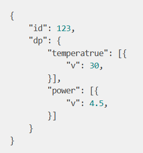
Figure 8 shows a payload format example. Figure 9 shows a schematic diagram for
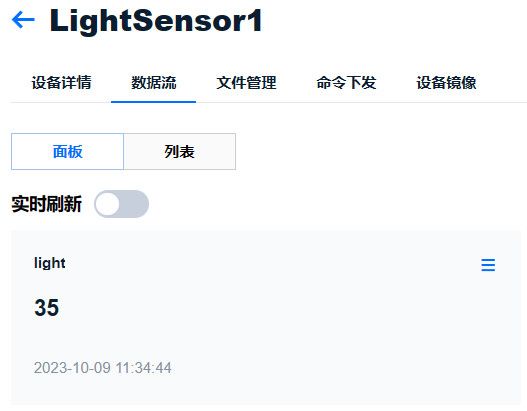
light value updates. The schematic uses an external watchdog timer because it cannot be fed during sleep mode, requiring an enable function. In the power supply section of the schematic, a J1 is connected to the HT7333-A output port. When using it, simply connect the jumper cap or solder it to a short circuit; alternatively, you can remove it. I added J1 during my previous debugging. Although an SD card slot is shown, considering the possibility of storing data locally, it is not currently used. The LED header connector on the schematic is connected to a 1.14-inch TFT screen, only used during debugging. The connection is: 1.14-inch TFT display screen.
The PCB design notes indicate that
the PCB layout has not been extensively optimized; you are welcome to modify it according to your own ideas.
The STM32 code notes specify that
the .c files for each task in the RTOS are located in the Tasks folder. The User_Tasks_Init(void) function in user_TasksInit.c is the task initialization function, replacing the MX_FREERTOS_Init(void) function generated by cubemx. When
you receive the code, you need to modify the code in the onenet_MQTT.c file according to your OneNet device information, adding your product ID, device name, and signature value, as shown in Figure 10. Due to security concerns, the value in the sign field in the provided code will be incorrect to prevent users from connecting to my devices.
In addition to uploading illumination intensity data to the edge device, I have also implemented cloud-to-edge command delivery, i.e., subscribing to a cmd topic on the device. For details on topic subscription and string processing, please carefully review the STM32 code. Figure 10 shows the Python code
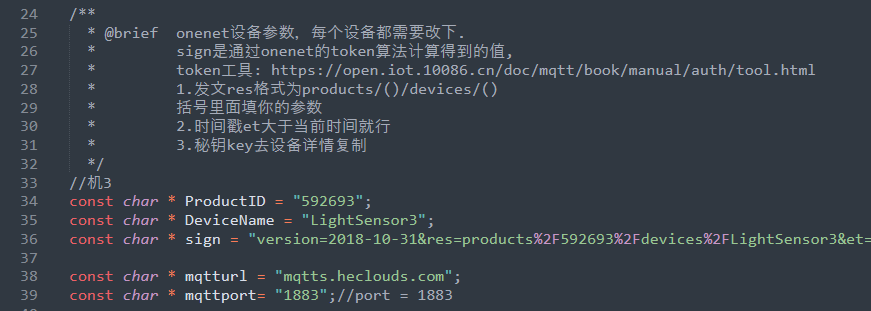
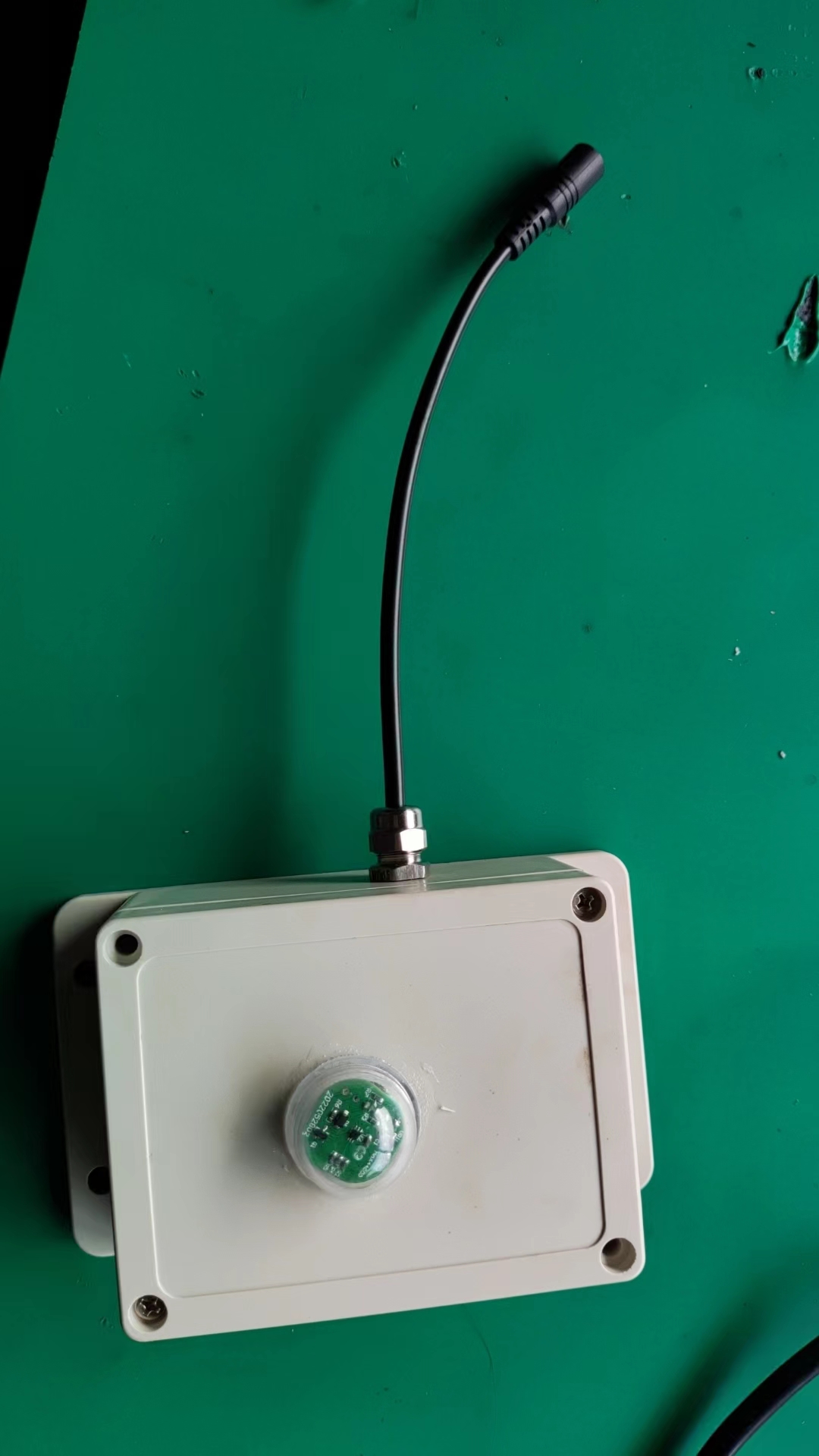
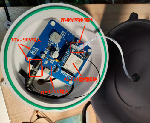
for modifying parameters in the onenet_MQTT.c file. I've provided two Python files: Onenet_getdata.py and token_ge.py, used to retrieve physical data from devices in OneNet and generate tokens, respectively. The retrieved data is returned in JSON format. Note that the product ID, device name, and product key in the code also need to be changed to your own parameters. Details of this information can be found on your OneNet developer platform; simply copy it. I won't demonstrate it here. The physical product with the casing is shown in Figure n. The casing was purchased directly from Taobao; ensure it's waterproof. A 12V female-male connector is used to connect to the monitoring power supply, which is then connected to an external 12V DC input. The disassembled physical product is shown in Figure n. This casing is 3D printed and will not be used later. The positions of the light sensor and the Air724UG plug-in module are marked in the figure; these can be directly plugged in. Figure 11: Physical image of the device with its casing. Figure 12: Disassembled physical image . Next is the actual device testing. Here, I captured data from the device in my dorm room while I was having dinner, as shown in Figure n. Since I'm currently attending classes elsewhere and don't have the device with me, I'm only showing images of previously recorded data. As mentioned before, this device can send data at second-level intervals, but in reality, it may be affected by network latency, etc. During the final test, I found that some data intervals were 1 second and some were 2 seconds. I couldn't find the previous data, so I didn't show it. Figure 13: Cloud data display. Reference links: Luat Community: Luat Community (openluat.com). For purchase links of some modules , please see the blue hyperlinks in the text. Github link: https://github.com/No-Chicken/4G-OneNET-LightSensor

LightSensor_V1_2_OneNet code.rar
python_codes.rar
PDF_4G-OneNet-Outdoor Light Acquisition System.zip
Altium_4G-OneNet-Outdoor Light Harvesting System.zip
PADS_4G-OneNet-Outdoor Light Acquisition System.zip
BOM_4G-OneNet-Outdoor Light Acquisition System.xlsx
91466
Homemade Electric Clothes Drying Rack
There are many electric clothes drying racks on the market, but they are either expensive, difficult to install, or have limited functionality. Therefore, I decided to design a better clothes drying rack myself. A demonstration video is attached.
I. Structure (STP attached)
A 540 geared motor (note: with an optocoupler that automatically triggers upon reaching a certain number of revolutions) is used as the power source to drive a 3D-printed spool. The clothesline is raised and lowered via a pull-string method. The expected load capacity is 25kg. Multiple fixing methods are available: it can be fixed to the ceiling via screw holes on the base, to an existing clothesline via round holes on the side, or to an existing folding clothes rack via square slots on the side.

II. Circuit (Please refer to the actual circuit in the BOM)
This project has two mainboards. Mainboard 1 uses an ESP32 microcontroller as the main controller, with relay-driven motors and optocoupler detection for clothing height. It also includes a 7.2V 6000mAh lithium battery (with charging circuit) for use during power outages. Mainboard 2 is an emergency lifting mainboard, using a 555 timer and switches to control the motor speed and direction, resulting in a lower failure rate. It can also connect to a high-power external power supply. The outputs (motor) of the two mainboards are connected in parallel.
III. Control Method
Normally, Alibaba Cloud IoT Studio is used, allowing control of the clothesline's raising and lowering via a mobile phone or computer webpage. (Following Mainboard 1) During a power outage, because the clothes rack has a built-in battery, you can continue to control its raising and lowering using your mobile phone or computer web browser by turning on a hotspot. (Following Mainboard 1) When Alibaba Cloud IoT Studio is unavailable for any reason, the clothes rack can be raised and lowered semi-automatically using the knob and switch. (Following Mainboard 2)
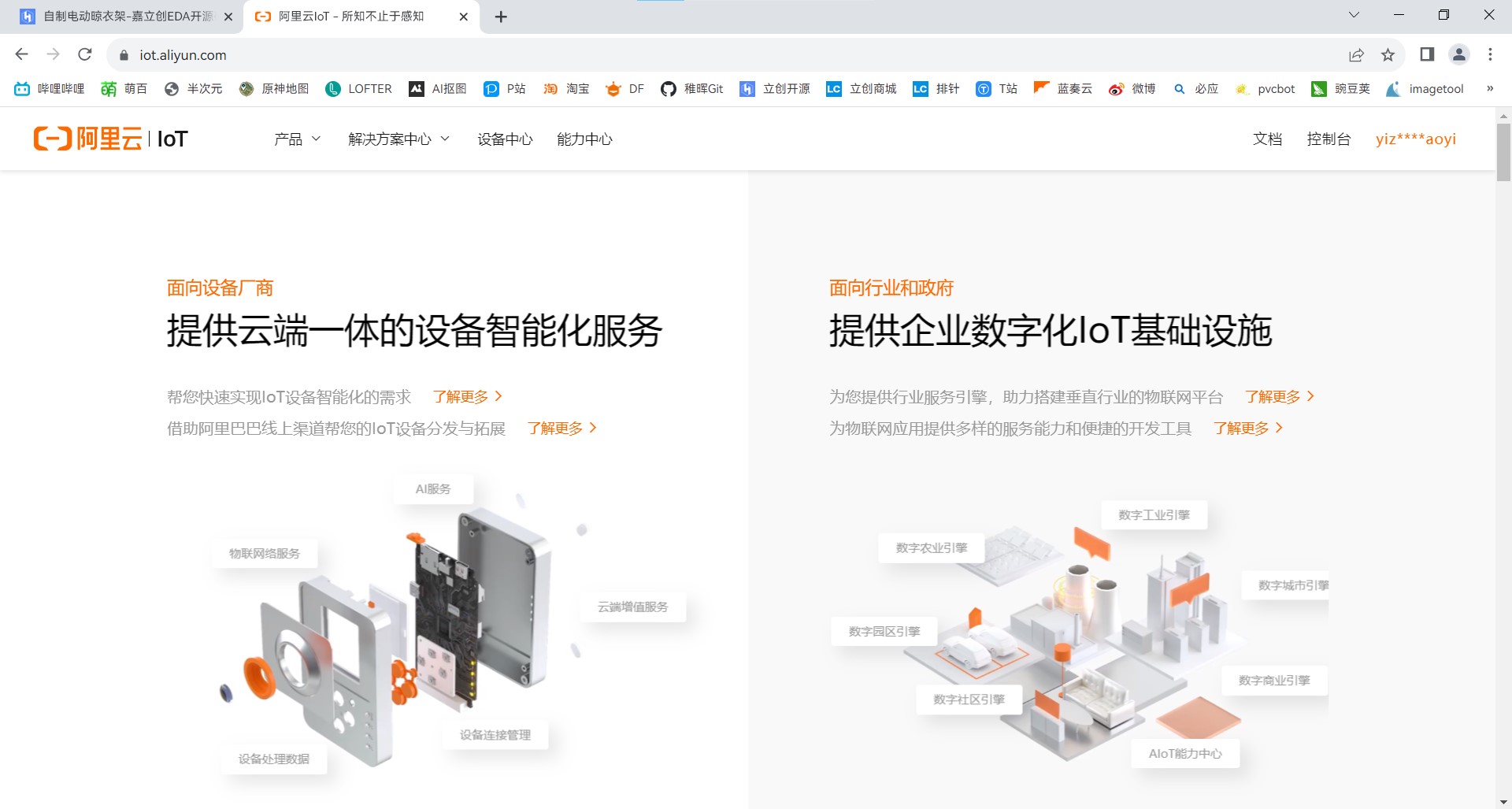
IV. Alibaba Cloud IoT Studio Registration Method
Open your browser, enter the URL https://iot.aliyun.com, enter the Alibaba Cloud IoT interface, and follow the instructions to complete registration and real-name authentication.
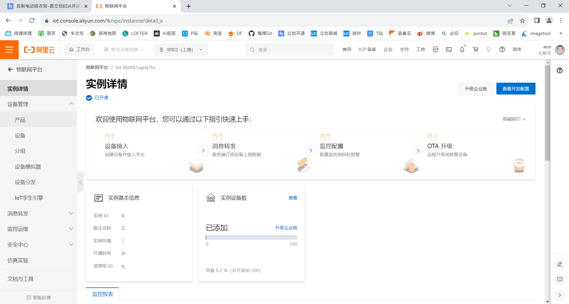
Click to enter the IoT platform

, select to activate IoT services, and follow the prompts until the service is successfully activated. Click on the management console to enter the console.

Users can complete the creation of products and devices, as well as the development of corresponding services, in this console. All steps in this tutorial are related to this console.
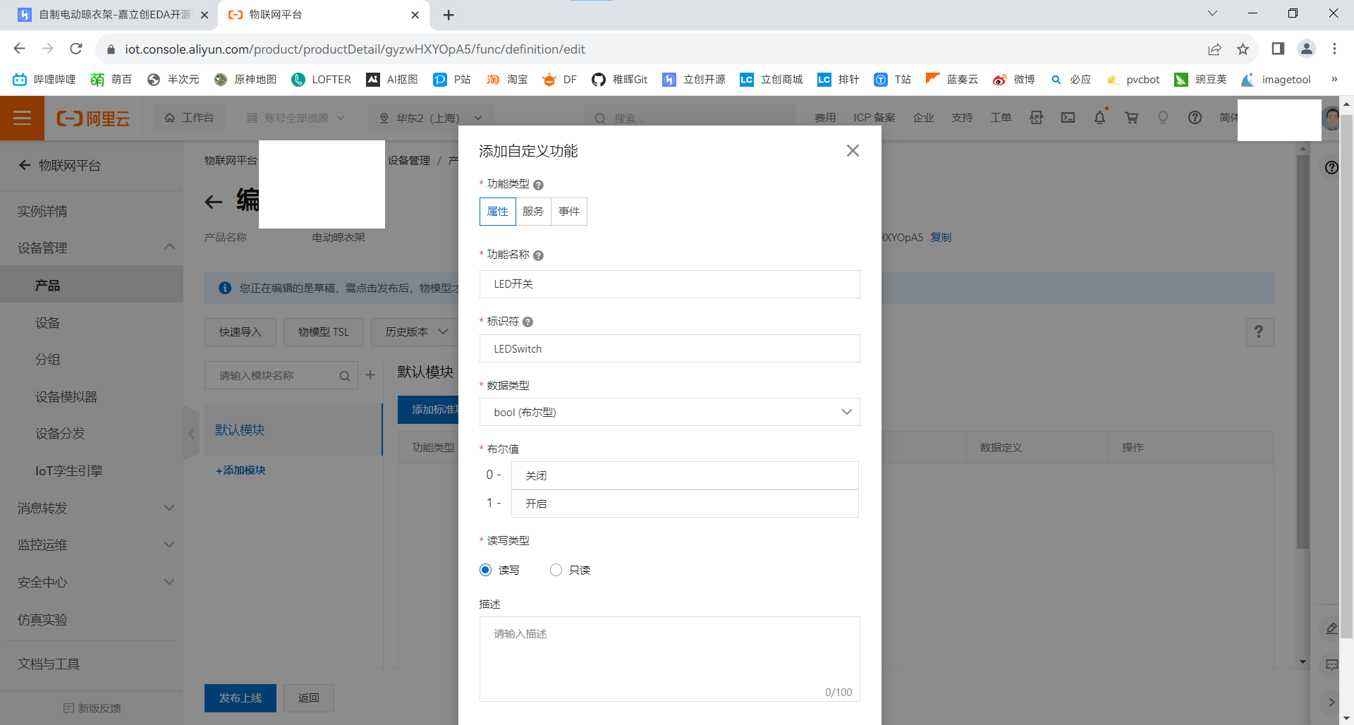
Enter the example (service) you just created, create a new product,

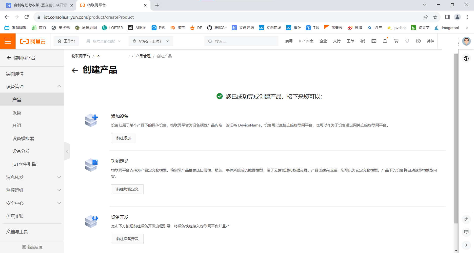
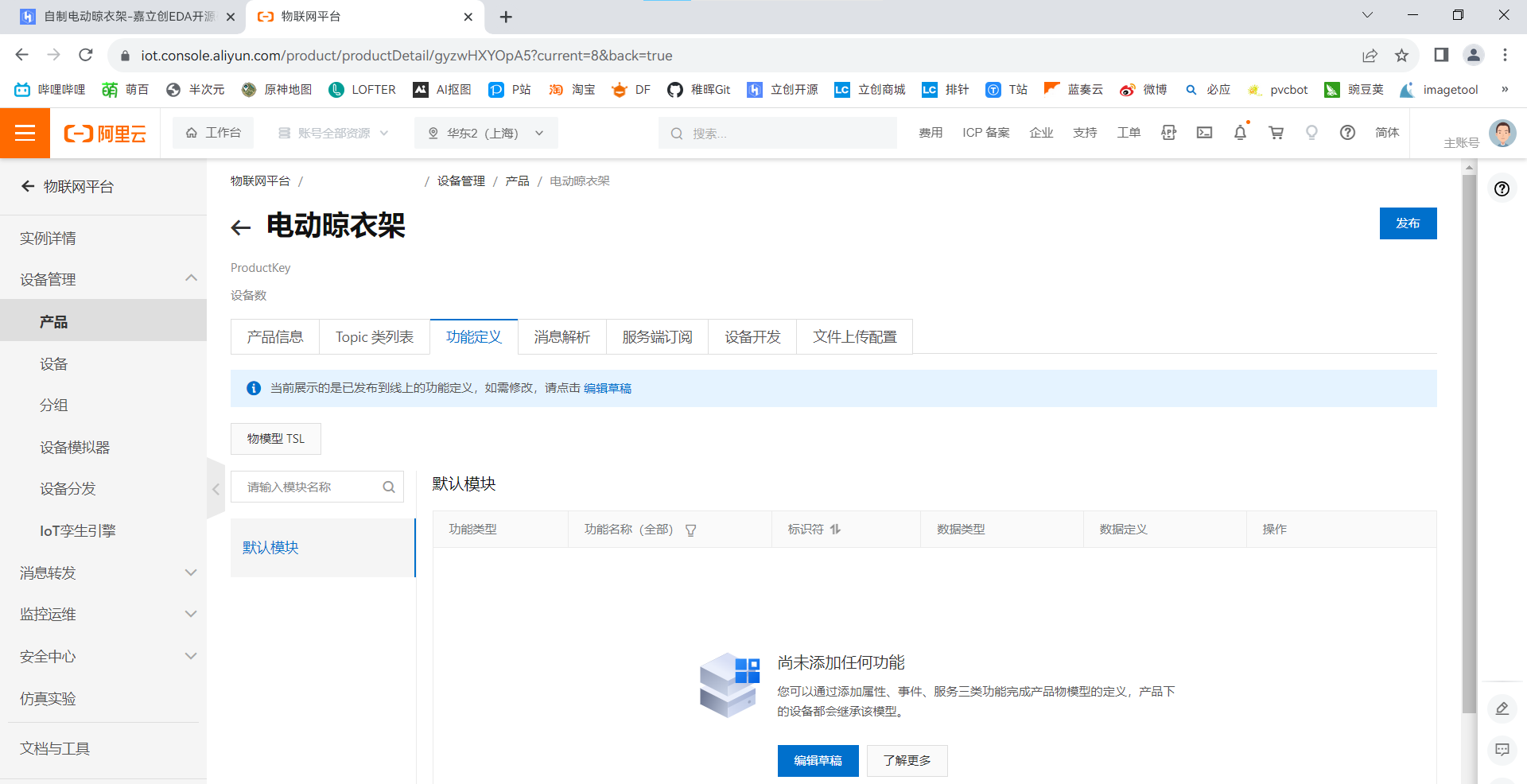
and then click on Product - View
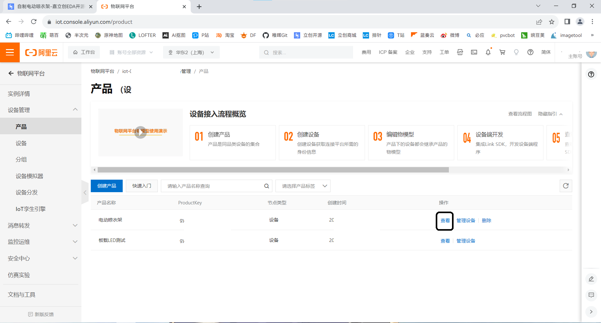
Function Definition.
Click on Device on the left - Add Device.

Enter https://studio.iot.aliyun.com/projects, create a new project
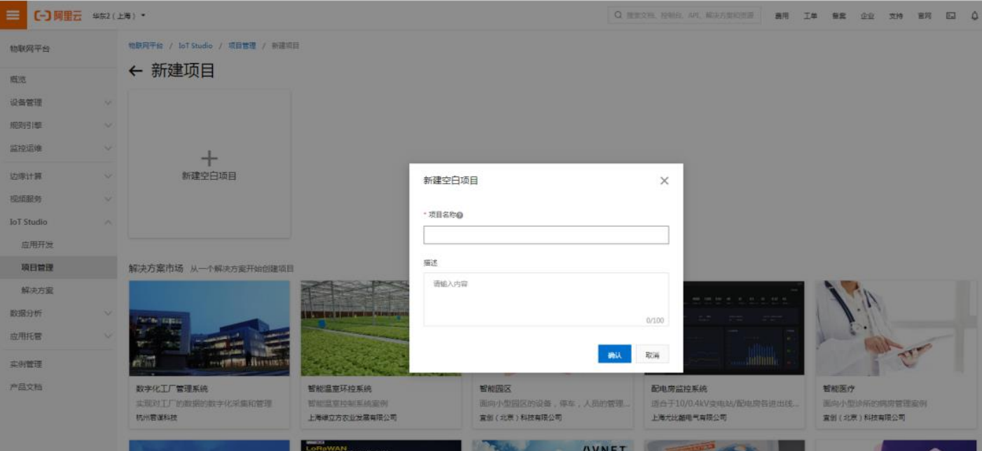
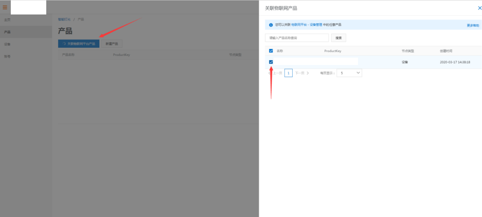
. Find the project you just created in the project list, click it, and enter the project overview page. We can import pre-created products at the bottom of the page (Note: Products already in a project cannot be imported into other projects). Click on a product in the overview page, then click on Associate IoT Platform Products. A dialog box will pop up; select the product to import into the project.
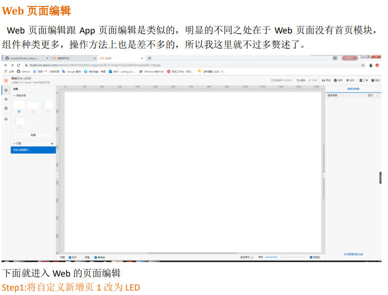
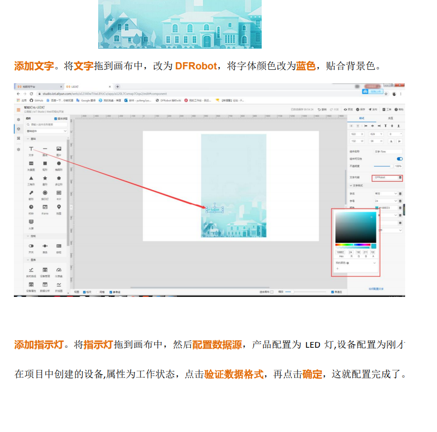
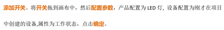
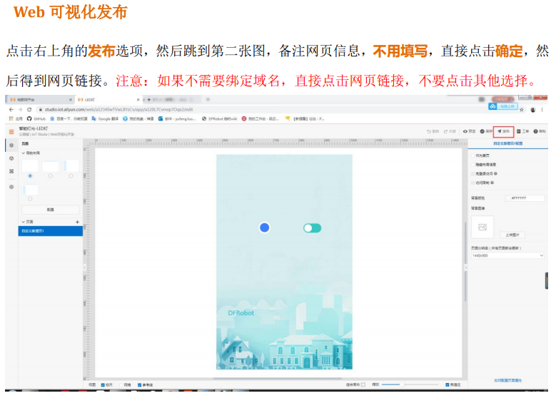
Finally, proceed with web visualization development. Here, I've directly copied someone else's tutorial.


V. Code:
First, install the DFRobot_Aliyun library file in the attachment.
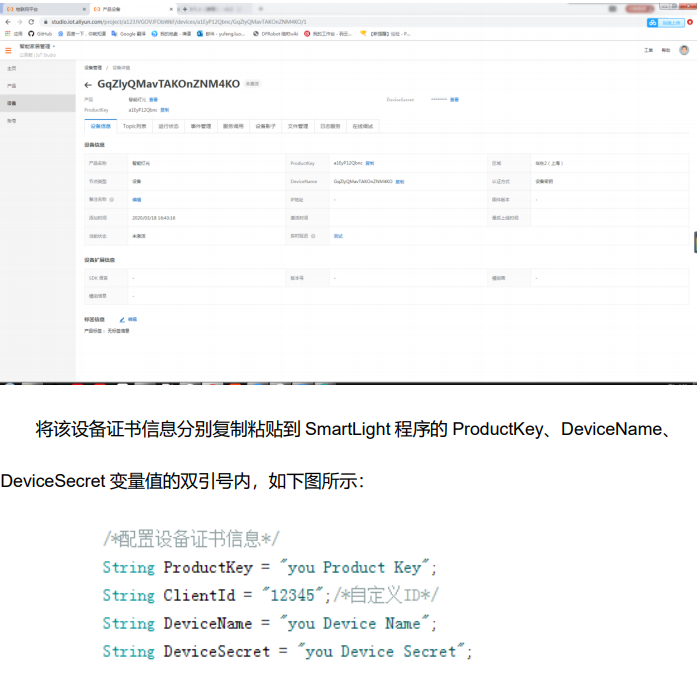
Then open the 191980.ino file in the attachment and modify the following content. Due to privacy concerns, this section uses the official tutorial.
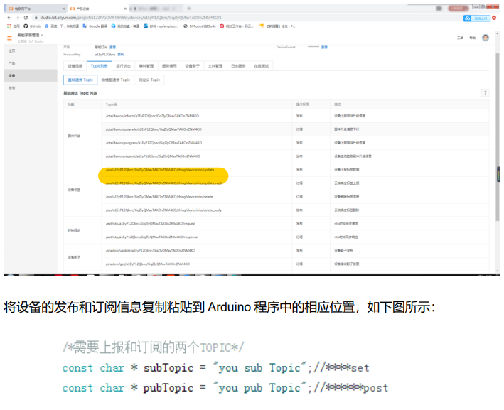
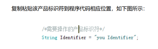
Then upload the program.
DFRobot_Aliyun library files.zip
191980.zip
The final assembly is used for screenshots. 123dx
Motor fixed.stp
terminal .stp
Support A.stp
Support base B.stp
studio_video_1695976246784.mp4
PDF_DIY Electric Clothes Drying Rack.zip
Altium_DIY Electric Clothes Drying Rack.zip
PADS_DIY Electric Clothes Drying Rack.zip
BOM_DIY Electric Clothes Drying Rack.xlsx
91468
electronic


 京公网安备 11010802033920号

 HPR122


