Voltage and Ammeter Function Definitions (Welcome to learn and exchange ideas)
1. Voltage Measurement (0~30V, two-level switching)
2. Low-side Current Measurement (0~3A)
3. High-side Current Measurement (0~1A, three-level switching)
4. Adjustable Power Supply (with current measurement 0~5V 0~1A)
Hardware Design:
Digital Tube Display Circuit
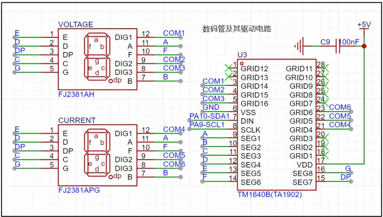
Considering MCU resources and expansion interfaces, the TM1640 digital tube driver chip is used to control the digital tube display. Driver adaptation was performed based on the specification sheet and online code resources, and the display interface was designed and implemented.
The power
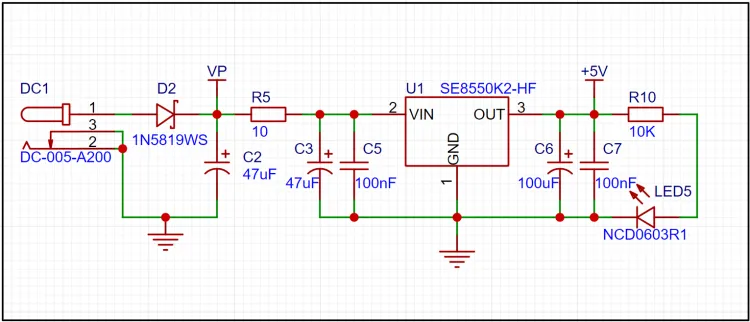
supply circuit primarily uses an SE8550 to regulate the DC/VP power supply to 5V, which powers the entire circuit board and the MCU.
Additionally, for various development and usage scenarios, a +5V external power supply path is provided. This can be achieved through a 5×2 female connector (pin 3) and a 0-ohm resistor connected to the MCU's 5V pin (the CW32F030 minimum system board has a 5V output port when using Type-C power, and this port can also be used as an MCU power input port in some scenarios).

In addition to the +5V external power input port, there are several reusable I/O ports. PB8 and PB9 can be used for UART and IIC (and also happen to be LED driver pins, so the LED will flash during communication).
PB15, PB14, PB10, and PB12 form an SPI (external expansion) group.
PA6 is a separate ADC channel.
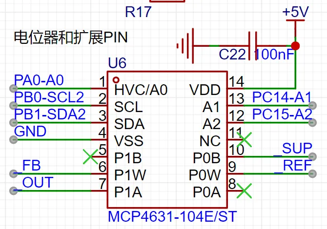
The adjustable power supply circuit

consists of a TLV7590 low-dropout linear regulator and a digital potentiometer, allowing dynamic adjustment of the output voltage by adjusting the resistance of the digital potentiometer.
The voltage measurement circuit

uses a voltage divider ratio of 220K and 10K to measure the input voltage (+V) in the 0~30V range. The software switches to the 0~3V range for measurement when the voltage is less than 3V.
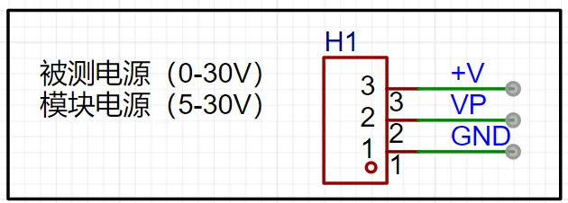
The voltage input port and the VP power supply port share a set of pin headers.
The voltage reference circuit
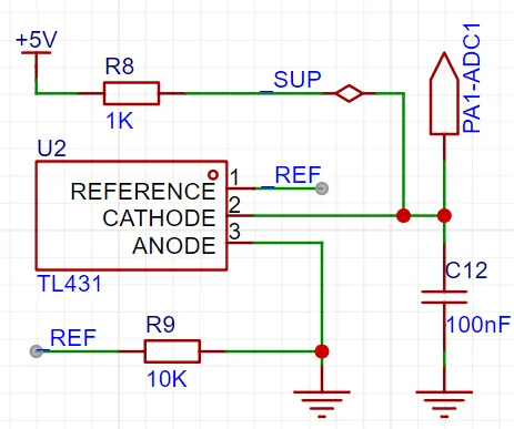
uses a TL431 for voltage sampling calibration and can also be used with a digital potentiometer to control the output voltage value (2.5V~3.8V measured). This is primarily for educational purposes.
The low-side current sampling circuit
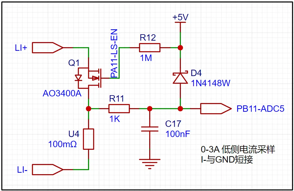
refers to the power supply flowing through the system under test before flowing into the sampling resistor. Here, we added a transistor control circuit (therefore, the voltage drop across this switching transistor needs to be considered when calculating the current; if the impact is significant, this circuit can be used to short-circuit it).
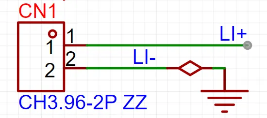
Below is the input port for low-side current sampling (L- is directly connected to GND): Compared to
low-
side measurement, high-side current measurement has two key advantages:
it can detect short circuits to ground within the load because the short-circuit current flows through the sampling resistor (which is not the case with low-side sampling),
and it is not affected by the differential voltage generated by the high current flowing through the ground plane (interference from the ground plane is usually significant).
However, high-side current measurement also has a limitation: it requires the current sense amplifier to have high common-mode rejection (I don't explain this very clearly; you have to look up some information to understand it). Here, we use the AD8237. For
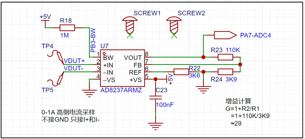
the sampling resistor, considering the need for small current sampling in some applications (mA, uA current measurement), a range switch is designed. The software controls the on/off state of the parallel resistor to switch the resistance value of the sampling resistor, thereby switching the measurement accuracy and range.

Finally, a mode switching circuit (switching circuit) is composed of high-side current measurement and an adjustable power supply.
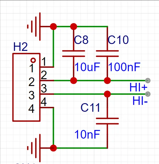
HI+ and HI- are the measurement input ports. In ammeter mode, HI+ is connected to the power supply, and HI- is connected to the load. In power supply mode, HI- and GND are connected to the load's power supply and GND, respectively.
The switching circuit on the right consists of three MOSFETs used as switches. In practical applications, their internal resistance (theoretically around 10mΩ) needs to be considered to affect the measurement results.
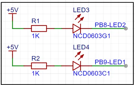
The button and LED circuits
are relatively basic, using the most cost-effective surface-mount packages from LCSC (they easily melt during soldering, haha).
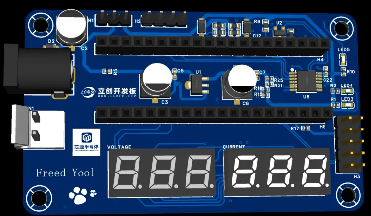
The PCB design
strictly controls the board size; most components are surface-mount, with only a small number of interfaces and digital tubes being through-hole components. Compared to the reference design, it is quite compact and refined.
Here are two renderings for a quick look. Regarding

the software design
, I'd like to introduce my development environment:
I use VScode + EIDE plugin + DAP-Link. Feel free to leave a message if you want to discuss your development environment!
The software code is still in the semi-finished stage. The high-side current measurement amplifier part is not yet working properly and we are still troubleshooting. So the current code is not the final product (but the adaptation code for the digital potentiometer and the digital tube driver is okay, and you are welcome to refer to it, discuss and exchange ideas). A
full-featured demonstration video will be released after the software is improved, but it is estimated to be quite a while later (around mid-September).
The key differences between this design and the reference design are explained below:
1. The voltage measurement circuit from the original project is retained, but the banana-head port used for external voltmeters and ammeters for verification and learning has been removed.
2. The TL431 circuit is retained, but a digital potentiometer is added to control its output voltage (reason for using a digital potentiometer: size considerations and learning purposes).
3. The low-current sampling circuit from the original project is retained, but a MOSFET switch is added to facilitate measurement mode switching.
4. The digital tube display is retained, but a digital tube driver chip is added (reason: insufficient MCU pins).
5. A high-current sampling circuit is added, consisting of three parallel measuring resistors of different resistance values and two low-on-resistance MOSFET switches. Range switching is implemented in software (software is available). An AD8237 instrumentation amplifier is also used (sufficient accuracy and relatively inexpensive with low bias current and 200K bandwidth).
6. An onboard LDO adjustable power supply (0~5V) is added to power the circuit under test, which is very useful when measuring the power consumption of different development boards.
7. Added an expansion PIN port, reserving one set of SPI, one set of I2C, and one set of UART for expanding more peripherals (such as temperature sensors or communication with a host computer);
8. Designed a 3D printed shell (first time making a shell, quite interesting haha);
PS: The PCB uses a four-layer board. The middle layer does not use the conventional GND and power supply. Instead, it is set as GND on the layer closest to the high-precision current acquisition circuit (bottom layer). Another layer has a small number of signal lines. Separate power supply traces are retained for the top and bottom layers. The reason for placing GND closer to the bottom layer is to provide some shielding for the high-precision current acquisition (I'm not sure if this understanding is correct). In addition, I want to explore the problems and effects caused by running signal lines in the middle layer through practice (learning purpose).


 京公网安备 11010802033920号

 MALREKX00AA147F00K


