I often work on small projects, many of which can be powered by lithium batteries. In these projects, the batteries are all housed in a casing, which, while offering high integration, still doesn't provide enough batteries.
This modular battery allows for plug-and-play operation and the ability to have multiple spare batteries.
The number of series and parallel connections can be set according to needs. A charger will be open-sourced later, allowing users to set the charging voltage and current based on the identification resistors on the board.
Example 1: A 1-series, 6-parallel battery pack, with a single cell voltage of 4.2V and a single cell capacity of 2600mAh, using 0.5C charging, which is a maximum charging current of 7.8A;
Example 2: A 1-series, 2-parallel battery pack, with a single cell voltage of 4.2V and a single cell capacity of 2600mAh, using 0.5C charging, which is a maximum charging current of 2.6A.
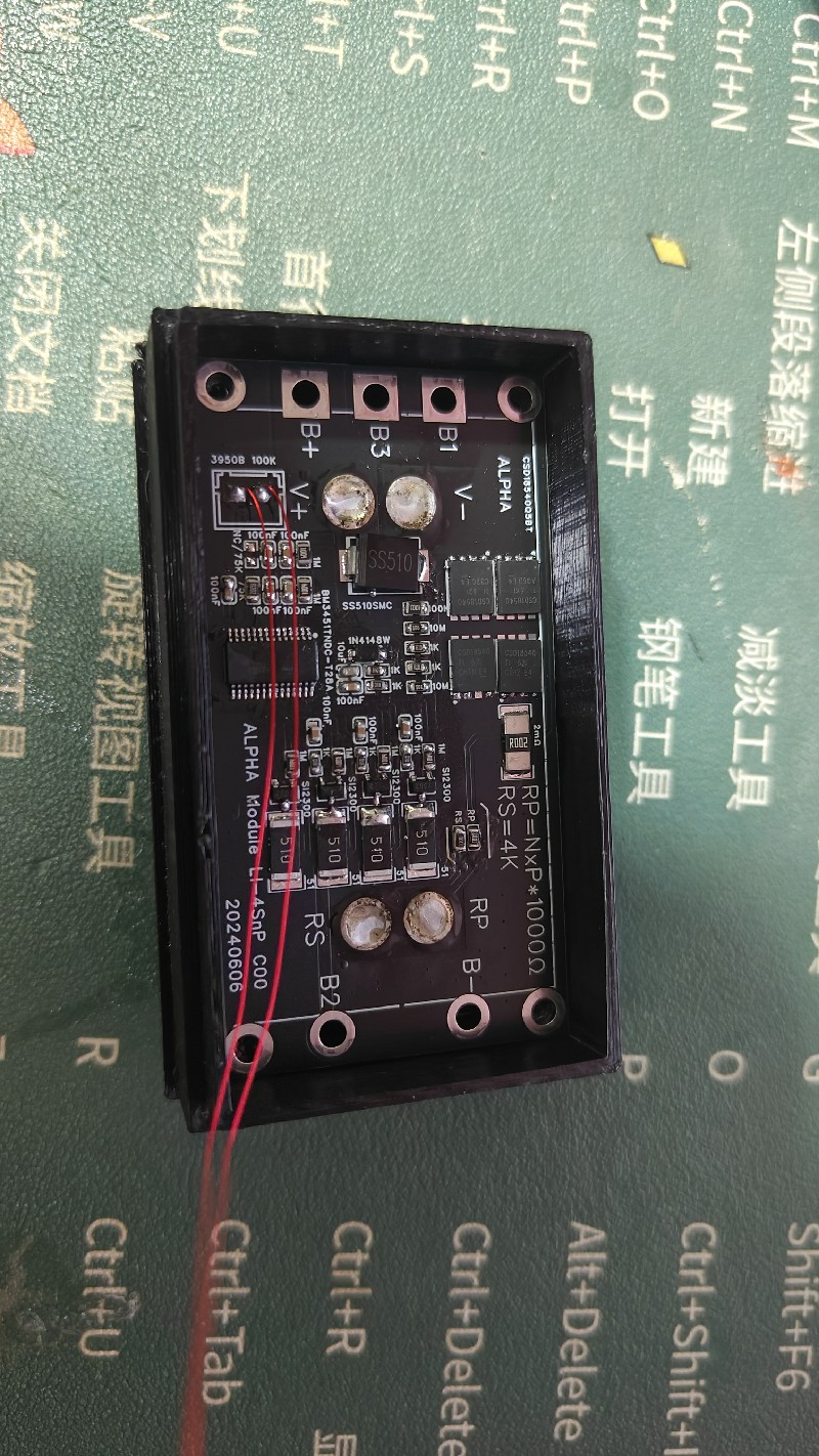
The resistors on the PCB are labeled RS (series setting resistor) and RP (parallel setting resistor).
The setting rule is: the number of series resistors equals the number of kilobytes (kΩ), and the number of parallel resistors equals the number of kΩ. For example, in a 1-series, 6-parallel configuration, RS=1KΩ and RP=6KΩ.
What if some resistors aren't perfectly aligned? The software will allow for a tolerance of ±400Ω, which I personally feel is reasonable.
Here are some reference resistance values: 1K, 2K, 3K, 3.9K, 4.3K, 5.1K, 6.2K, 6.8K, 8.2K, 9.1K, 10K, 11.2K, 12K…
Another important reason for doing this project is that I found cheap XT60 batteries on Taobao. I bought 80 sets (male and female connectors), with each set costing about 0.9 yuan. I also found brand new 18650 batteries on Taobao, buying 100 sets for less than 2.6 yuan each.
The battery specifications are approximately 2600mAh with a slightly larger capacity and around 18mR internal resistance, which seems quite worthwhile, cheaper than buying from secondhand sellers.
Also, the resistor identification uses XT60 batteries, which is a bit wasteful. I considered magnetic resistors before, but the current draw isn't very high, and they're more expensive, so they weren't suitable.
Using one XT60 and another other socket isn't a perfect height match. While it's workable, it's inconvenient. However, the price of this socket on Taobao is negligible…
The XT60 has a rated current of 30A and a peak current of 60A, which is sufficient.
For lithium battery connections, if you're using a welding machine, check out other open-source solutions. A few years ago, I made my own welding machine using two 3000F 2.7V farad capacitors in series. The power has always been plugged in, never unplugged, and it's still working perfectly—its lifespan is incredible. Farad capacitors were cheap back then; I think I bought those two for around 35 RMB including shipping, now they're around 90 RMB.
For NTC batteries, use thermally conductive silicone adhesive to attach them to the battery; safety first.
PDF_Modular Battery-4SnP.zip
Altium Modular Battery - 4SnP.zip
PADS_Modular Battery-4SnP.zip
BOM_Modular Battery-4SnP.xlsx
94282
thatmicpre_improve
This project is an open-source microphone preamp based on ThatMicPre, featuring a solid 60dB gain and supporting 48V phantom power, making it perfectly compatible with both dynamic and condenser microphones.
ThatMicPre is an open-source microphone preamp with a solid 60dB gain and supports 48V phantom power, perfectly compatible with both dynamic and condenser microphones. It features 12 adjustable fixed gain levels, avoiding noise caused by potentiometer adjustments. This project modifies the preamp using LCSC EDA and replaces some components for easier sourcing from the LCSC online store. Due to the preamp's prevalence and high price of counterfeit products, the compatible SSM2019 surface mount package has been added for user convenience. The overall design remains largely unchanged, with a redesigned layout and the addition of a 3.5mm headphone jack for easy connection to mobile phones or laptops for recording.
The original project is located at: GitHub - ojg/thatmicpre: Microphone Pre-amplifier
License: CC-BY-SA-4.0 license
PDF_thatmicpre_improve.zip
Altium_thatmicpre_improve.zip
PADS_thatmicpre_improve.zip
BOM_thatmicpre_improve.xlsx
94284
Simple cooling fan control board
Using a spare cooling fan, I designed a simple cooling fan control board. It supports 12V and 5V power input and fans with a size of 5-9cm. It can be used as a cooling fan or a small fan for venting soldering fumes.
This is a simple cooling fan control board that supports DC 12V/5V input and 5-9cm cooling fans (8cm fans are recommended; 9cm fans may cause size interference during assembly). It can be used as a cooling fan or a small fan for soldering fume extraction.
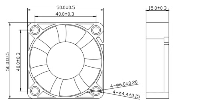


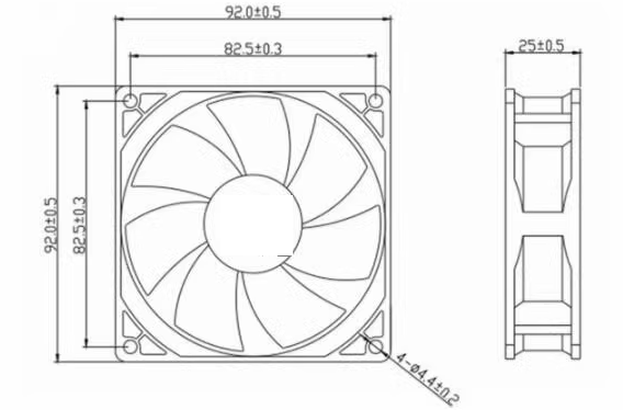
Regarding fan size: a moderate size is recommended; smaller fans may not produce much airflow.
Regarding the casing: it's optional; a bare fan with a color silkscreen print looks good.
Regarding assembly: 1. The fan can be secured to the PCB using M3-M4 screws and nuts (I used the screws that came with my previously purchased Deer Fairy heating plate).
2. The casing is secured with M4 screws.
3. The filter for the soldering fume extraction fan can be placed between the casing and the PCB, in the following order: front casing - filter - PCB - fan - PCB - rear casing. Alternatively, if you don't want a separate casing, you can add a PCB at the front during fan assembly, in the order of PCB - filter - PCB - fan - PCB.
PDF_Simple Cooling Fan Control Board.zip
Altium Simple Cooling Fan Control Board.zip
PADS Simple Cooling Fan Control Board.zip
BOM_Simple Cooling Fan Control Board.xlsx
94285
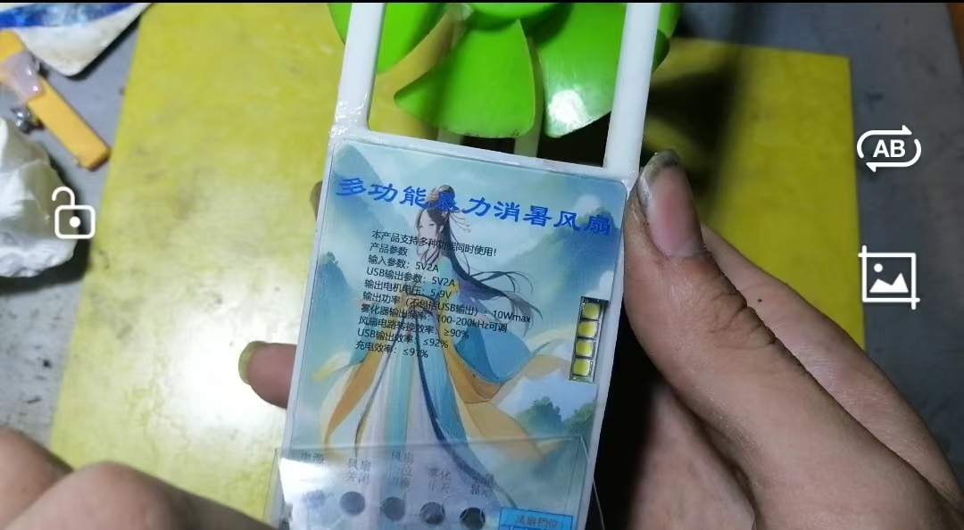
Multifunctional cooling fan
Using the CD4017 as the main control chip and the 3843 power supply chip as the PWM chip, the motor speed is no longer controlled by PWM, but by voltage. The 3845 chip is used as the atomizing chip, achieving high atomization volume and low power consumption. It also features power bank and flashlight functions for convenient outdoor use.
Project Overview:
The CD4017 is used as the main controller and buttons instead of potentiometers to achieve wind speed adjustment. This reduces size and avoids the problem of adjustment failure caused by poor potentiometer contact.
Motor speed is no longer controlled by PWM, but by voltage control, as it's a boost circuit and voltage control is more convenient.
The 3843 power chip is used as the PWM chip, reducing project manufacturing costs (a low-voltage PWM chip is significantly more expensive than a 3843).
The 3845 chip is used as the atomizing chip, achieving high atomization volume and low power consumption.
It includes power bank and flashlight functions for convenient outdoor use.
Project Cost:
There are two production cost options. One is to replicate the project source files (this option is more expensive and not recommended, and the project cost may exceed 150 yuan (including various coupons)). The other is to use the low-cost option I used (the PCB does not need color silkscreen printing, which also saves costs). Here's
a brief overview of the approximate project manufacturing cost. Besides the 50 yuan coupons for color screen printing, panel printing, 3D shell printing, and components, some components were salvaged from scrap metal boards, essentially free (including the fan blades). The motor is a type from DVD players, about 25mm in diameter and 12mm high, with wiring. I used a salvaged one, so it didn't cost me anything (actually, a new one only costs a few yuan with free shipping; you can buy it online). The atomizing disc was bought online; it's about 20mm in diameter, I think it was 3 for 10 yuan, I don't remember the exact price, but it wasn't expensive.
Note that if you are prototyping the 3D shell and ordering the panel, as well as purchasing components from LCSC Mall (all electronic components except motors and atomizers can be found on LCSC Mall), you will need to pay for shipping (my shipping cost is 7 yuan, but it may vary depending on the region, because I used LCSC Mall coupons and shipping vouchers; shipping the panel prototyping and components purchased from LCSC Mall together can save on shipping costs). However, please note that 3D prototyping coupons and shipping vouchers cannot be used together, meaning you still need to bear the shipping costs yourself (my shipping cost is 5 yuan, but it may vary depending on the region). Moreover, the more complex the model design, the higher the prototyping cost. In order to make free prototyping for this shell, I have removed most of the reinforcement and slotting designs. Of course, some parts still need to be prototyped back for secondary processing.
Function Overview:
Features a 5V/2A Type-C charging input and a 5V/2A USB output
; power display (short press to turn on, double press to turn off (can also control USB output))
; flashlight function (long press to turn on and off)
; atomization function
; 4-speed fan control
; one-button fan off and one-button fan and atomization off.
All functions can be controlled independently.
Product parameters
are detailed on the panel.

Materials required:
A sample panel, a set of 3D shells (self-printing can save costs), an atomizing plate and a motor (these two components are mentioned in the project cost), two high-capacity 18650 batteries (I used salvaged ones; appropriately sized soft-pack lithium batteries can be used, but the protection board current must be greater than 4A), a salvaged fan blade (approximately 75mm in diameter), and a soldered and tested circuit board.
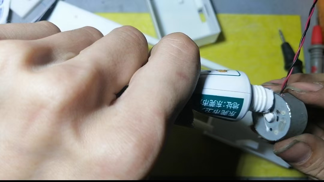
For motherboard testing
, first connect the motherboard to the battery, measure the motor output voltage and check if the buttons operate normally.
Connect the motor, measure the conversion efficiency and maximum input current (normally should be ≤2.5A).
Connect the atomizing plate and turn on the atomization function. At this time, the green indicator light on the motherboard will light up. Adjust the potentiometer to maximize the atomization volume.
Turn on all functions and the fan speed to maximum. At this time, the motherboard should be able to control the flashlight, atomization function, and master switch function.
Once all the above tests pass, you can proceed with assembly .
For
the sample shell from the source file, you can skip the shell processing steps.
Prepare the sample shell (the shell has been modified here to enable free sampling and will differ from the source file).

Cut as shown in the figure.

The circled area needs to be cut with a groove about 1.5mm wide and 1mm deep.
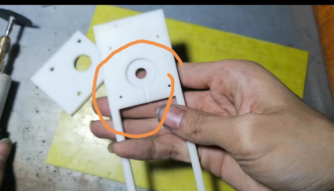
Here, a 5*5mm hole needs to be cut

. Break it off at this position (it is recommended to cut it with a knife before breaking it off).
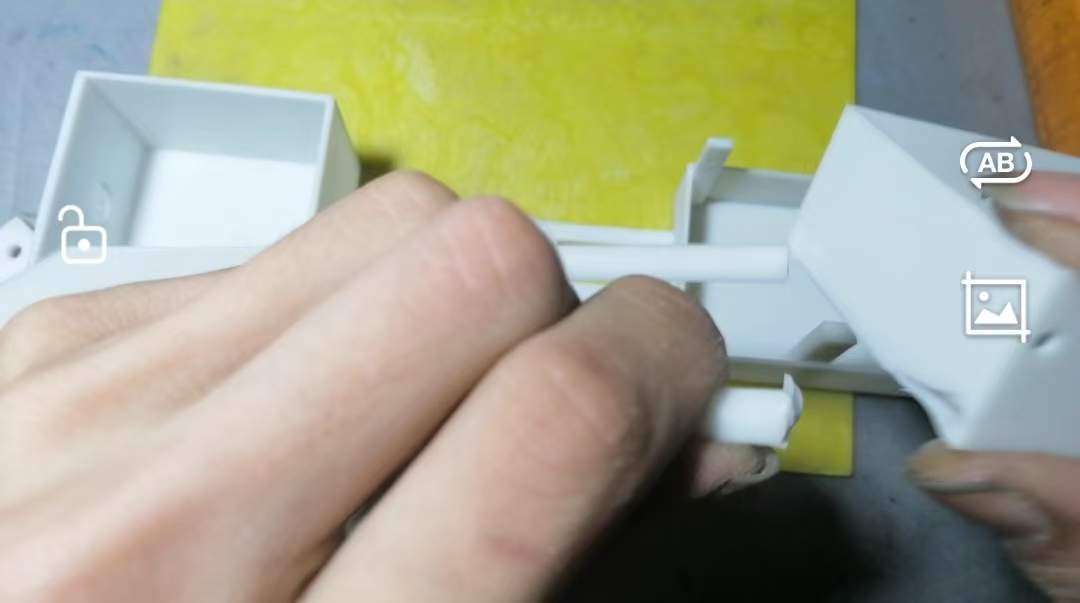
Then glue these two parts together with AB glue.
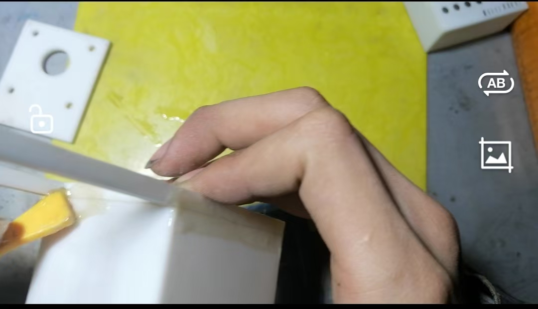
Here, cut a suitable wire groove (about 1mm deep and 2mm wide).
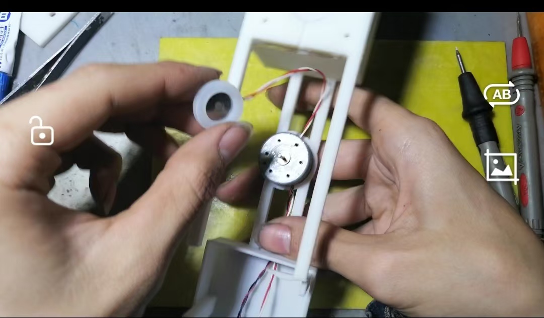
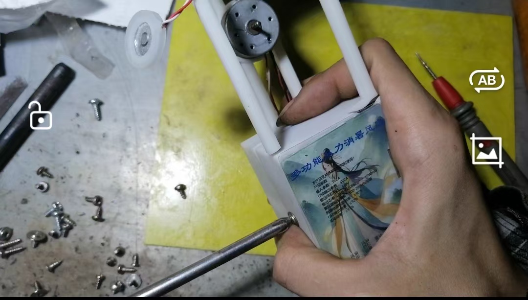
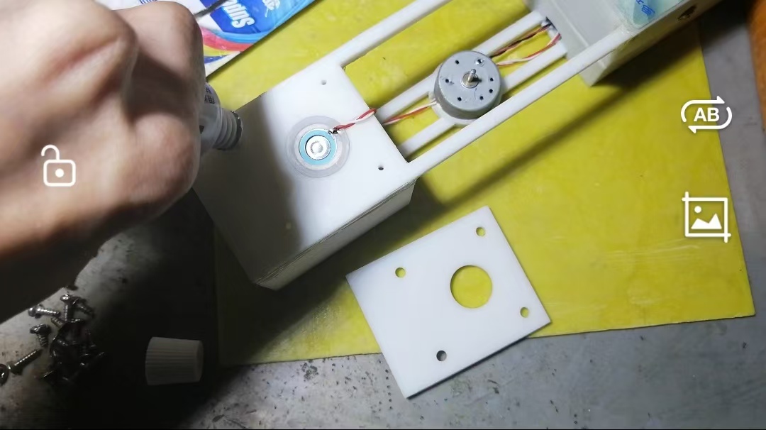
Apply 704 silicone rubber to the motor. Press the
motor into the socket, leave an appropriate length for the atomizer wire, and thread the remaining wire through the hole.
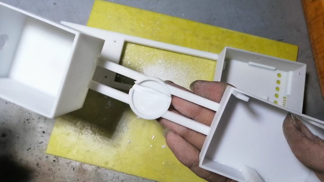
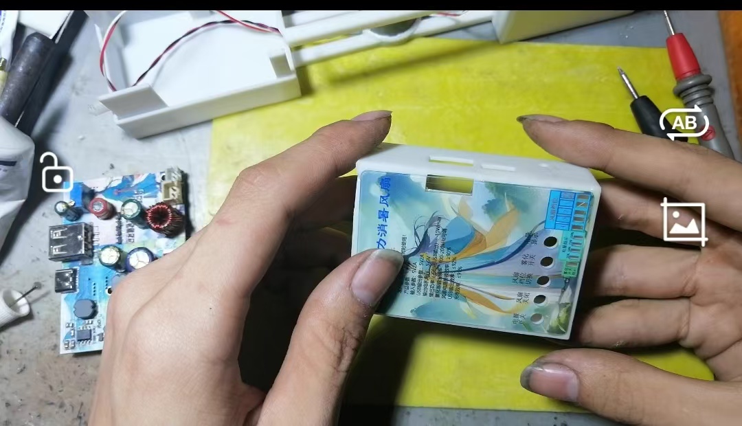
Place the circuit board into the casing.

Apply the glue used for phone back covers to the back of the panel (remember to remove the protective film on the back).
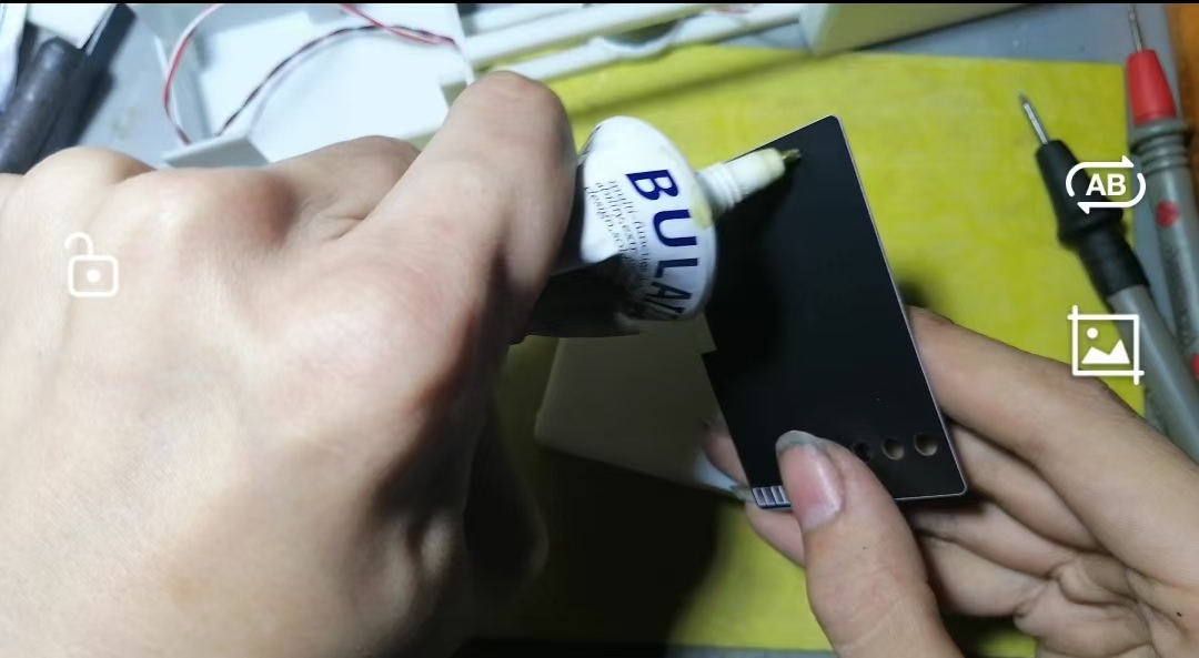
Align the panel holes and attach them.
Attach all the ribbon

cables. Apply 704 silicone rubber to the battery (double-sided tape can be used instead).

Attach the battery, cover

the casing
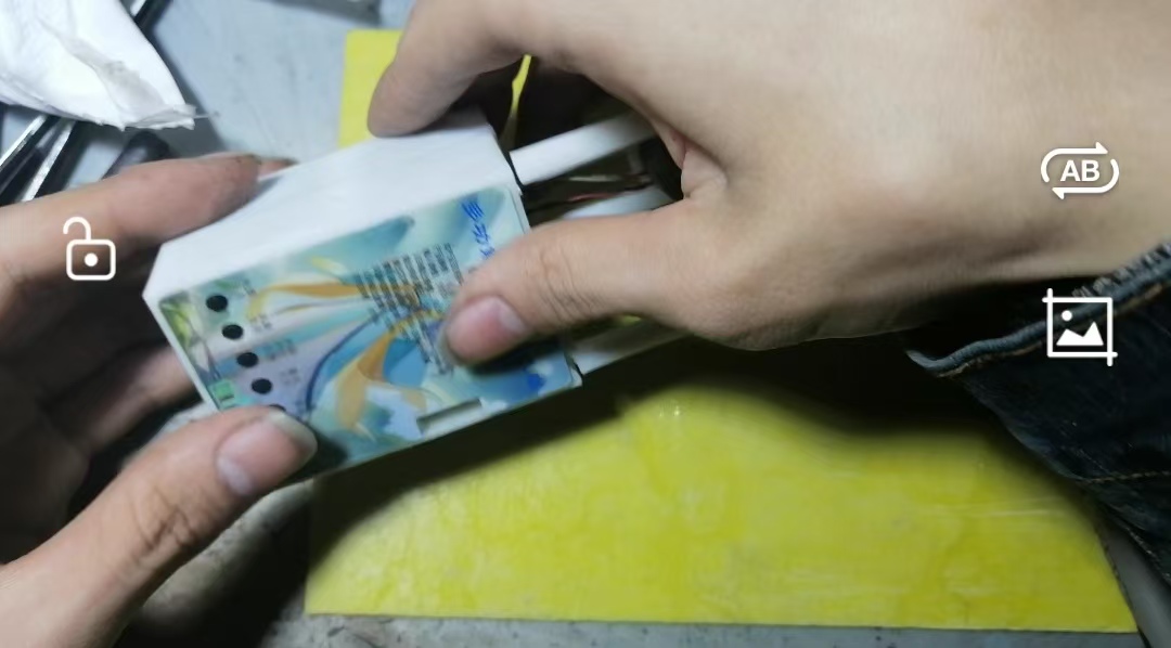
, and screw on the screws (actually, the circuit board is fixed by the internal support feet of the casing, so you don't need to glue the circuit board).
Use AB glue to firmly bond the broken parts. Secure

the atomizer wire with transparent tape.

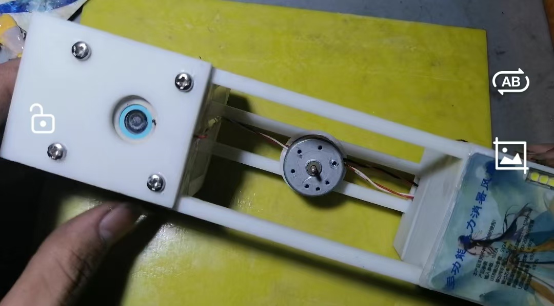
Place the atomizer and apply 704 silicone rubber to the screw holes to prevent water leakage.
Cover the cover and screw on the screws .
Install the fan blade (this fan blade is from a disassembled device; see the materials preparation for dimensions. You can also 3D print it or buy a ready-made one).
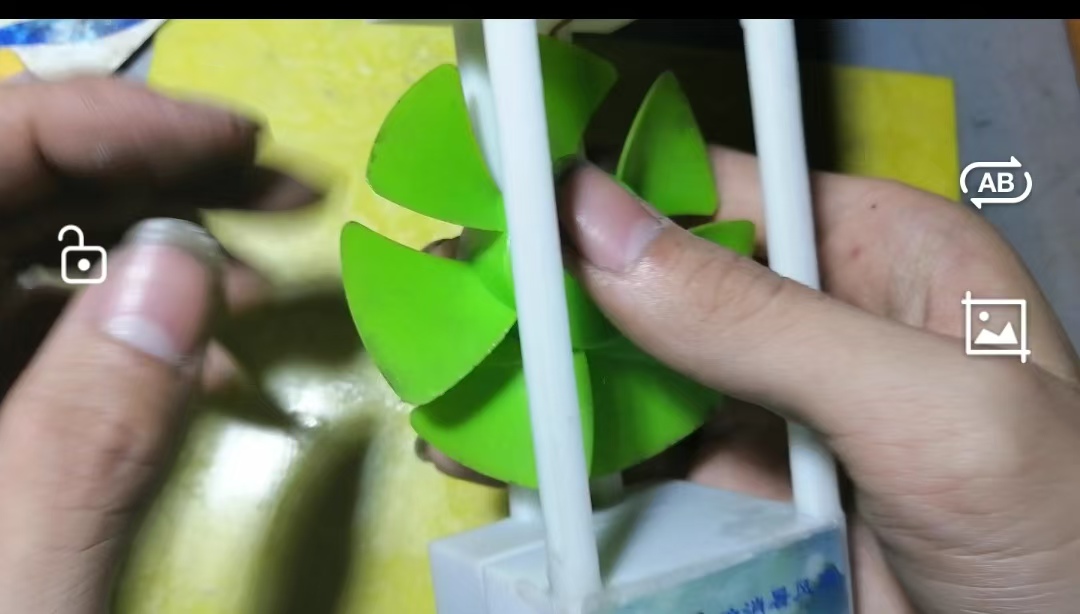
Remove the protective film from the front of the panel.
The assembly process is now complete.
Test video link:
Since the entire project (including test videos) was uploaded to Bilibili, only the link to the first video in the collection is provided here. To watch other videos, please go to the collection and select them.
Video link
: https://www.bilibili.com/video/BV1Bz42127J3?t=3.5
Notes on
transformer winding: Two 10*6*4.5mm magnetic rings are stacked together. Two 0.51mm enameled wires are wound together for 12 turns (make sure the winding is smooth). Then leave a tap and continue winding for 4 turns in the same direction. Then cut the center tap and install it on the circuit board according to the schematic.
To save costs, you can use a reduced version of the 3D shell file for prototyping, or you can design your own.
The attached file includes a test video.
The water inlet plug needs to be made by yourself using a rubber plug, or you can design your own.
If the power button cannot control the circuit, you need to adjust the parameters according to the text instructions on the schematic.
If the power switch circuit is normal, and there is voltage on the GS pin of the MOSFET controlling the power switch, but the subsequent circuit does not work, you need to replace the MOSFET with a new one (you can use a similar model MOSFET you have). In this case, the MOSFET's DS is usually open, but a multimeter cannot detect it, while the body diode is normal. Don't ask me how I know, because after checking this fault and replacing all the components, the only one left that wasn't replaced was this MOSFET. (Similarly, if the boost circuit is faulty (e.g., the switching transistor overheats abnormally, the drive signal is normal but it can't boost, the conversion efficiency is abnormal, etc.), you can also try replacing the MOSFET.)
Panel order parameters: 5mm thick acrylic sheet, ink-printed on the bottom, no adhesive backing (you can also choose the adhesive backing option when replicating). Two panel designs are provided in the attachment below: one with a cutout design, and the other with a raised button design.
A high-performance battery is recommended; ordinary batteries do not have sufficient discharge rate to support the device at full load.
The atomizer and motor cables will need to be extended if they are not long enough!
A Gerber file is included for easy ordering.
b9aaa0fc1a12c93cb9c9ed0b9bf2c1e8.mp4
3DShell_Violent Cooling Fan Source Files.zip
3DShell Multifunctional Summer Cooling Fan (Reduced Version).zip
Panel_Multifunctional Summer Cooling Fan Panel Bulging_2024-05-25.epanm
Panel_Fan Panel Cutout_2024-05-25.epanm
Gerber_Violent Summer Cooling Fan_2024-05-26.zip
BOM_Violent Cooling Fan_Violent Cooling Fan_2024-05-26.xlsx
PDF_Multifunctional Summer Cooling Fan.zip
Altium Multifunctional Cooling Fan.zip
PADS_Multifunctional Cooling Fan.zip
BOM_Multifunctional Cooling Fan.xlsx
94286
[Verified] MPPT solar charging panel based on CN3722
This is a CN3722-based solar charging panel; its functionality has been verified.
This is a solar power panel based on the CN3722. After four revisions, it's finally usable without any problems. Theoretically, the charging current can reach around 5A. Testing at 19V 1A, it reaches 20W. I charged a 9Ah 18650 lithium battery pack, and it went from about 20% to 70% in about half a day, which is acceptable. An INA219 chip has been added to the board to collect solar input power, voltage, and current information, but I haven't tested it yet. It should work fine. I expect further revisions later, as this power panel is for use with other boards.
Regarding the inductor selection, I think you could choose a cheaper one. I chose a higher specification one, but it depends on your needs. I used the one I had on hand. Making your own would probably cost around ten yuan, depending on your requirements.
d6dd657fd210f798236af85a7d5e262.jpg
PDF_【Verified】MPPT Solar Charger Based on CN3722.zip
Altium_【Verified】MPPT Solar Charger Based on CN3722.zip
PADS_【Verified】MPPT Solar Charger Based on CN3722.zip
BOM_【Verified】MPPT Solar Charger Based on CN3722.xlsx
94287
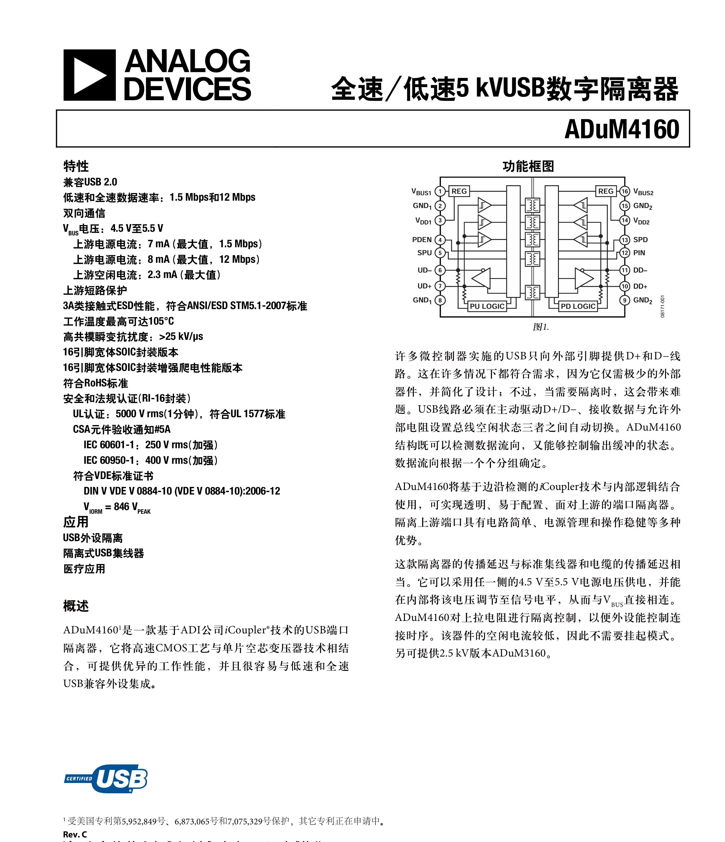
USB Isolation Hub ADUM4160+CH334
ADUM4160 + CH334, USB HUB
The ADUM4160 is used for USB isolation to ensure computer safety during experimental debugging.
The hub chip is CH334R, supporting high-performance MTT mode.
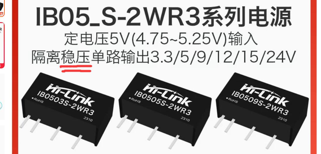
The power supply is an IB05_S-2W isolated power module.
This hub has 7 interfaces, 3 of which are 480Mbps full speed but not isolated, and 4 are 12Mbps full speed with complete data and power isolation.

The IB05_S-2W isolated regulated power supply is recommended for isolation.
Note that some isolated power supplies are "isolated unregulated power supplies," and their output voltage fluctuates with the power rating. They can still be used and function without problems.
To prevent voltage fluctuations from affecting the isolation chip, an ME6211 is used to step down the voltage to 3.3V to power the ADUM4160.
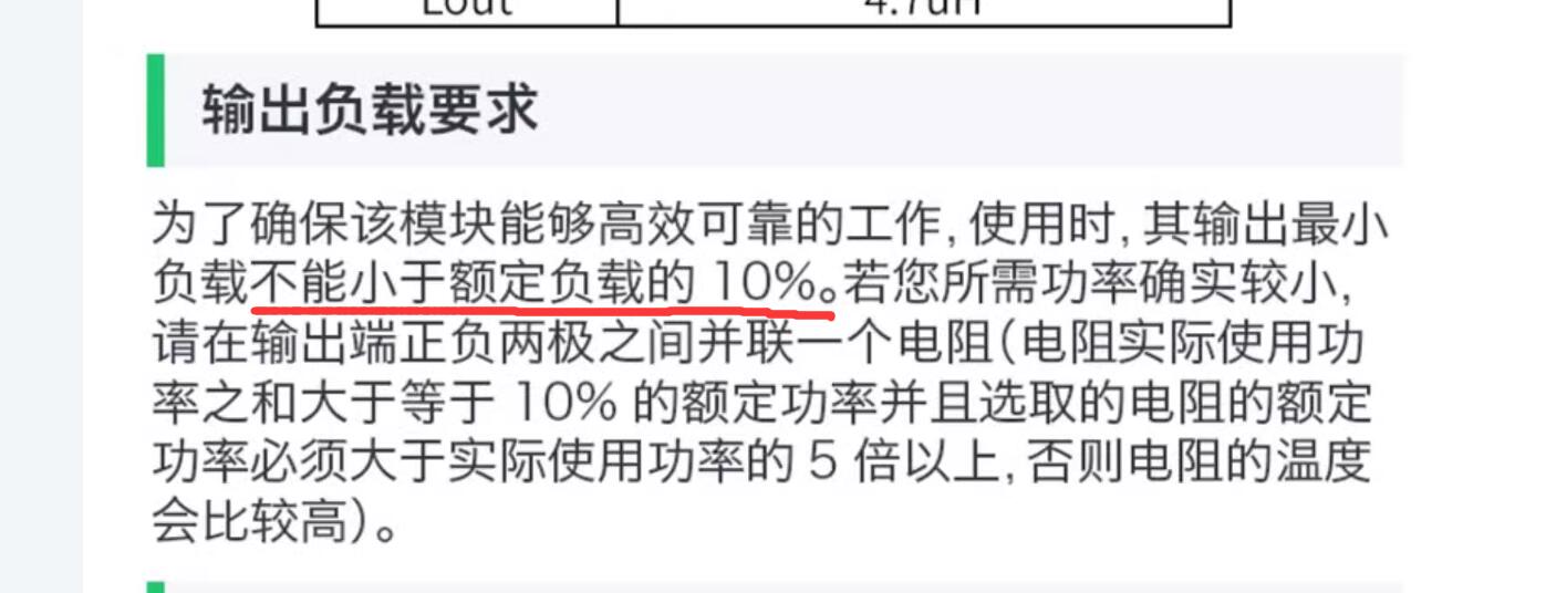
Because the isolated power supply has significant ripple under no-load, a resistor is added as a load.
PDF_USB Isolated HUB Hub ADUM4160+CH334.zip
Altium USB Isolated HUB (ADUM4160+CH334.zip)
PADS_USB Isolated HUB Hub ADUM4160+CH334.zip
BOM_USB Isolated HUB Hub ADUM4160+CH334.xlsx
94288
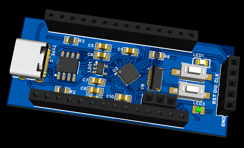
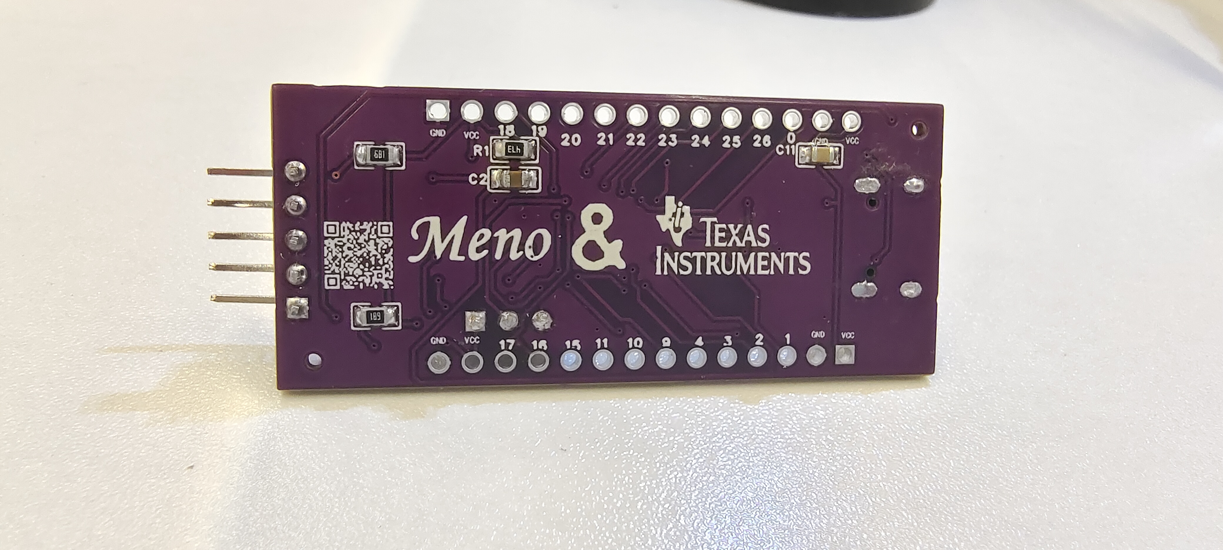
MSPM0L1306 core board
This design was created for an official TI innovation event and is prohibited from commercial use or reproduction. The design is based on the concept of a compact yet fully functional program, and also includes an onboard 0.96-inch TFT color screen, facilitating development and debugging.
PDF_MSPM0L1306 core board.zip
Altium_MSPM0L1306 core board.zip
PADS_MSPM0L1306 core board.zip
BOM_MSPM0L1306 core board.xlsx
94292
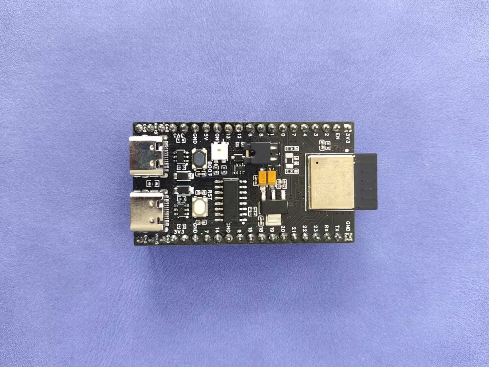
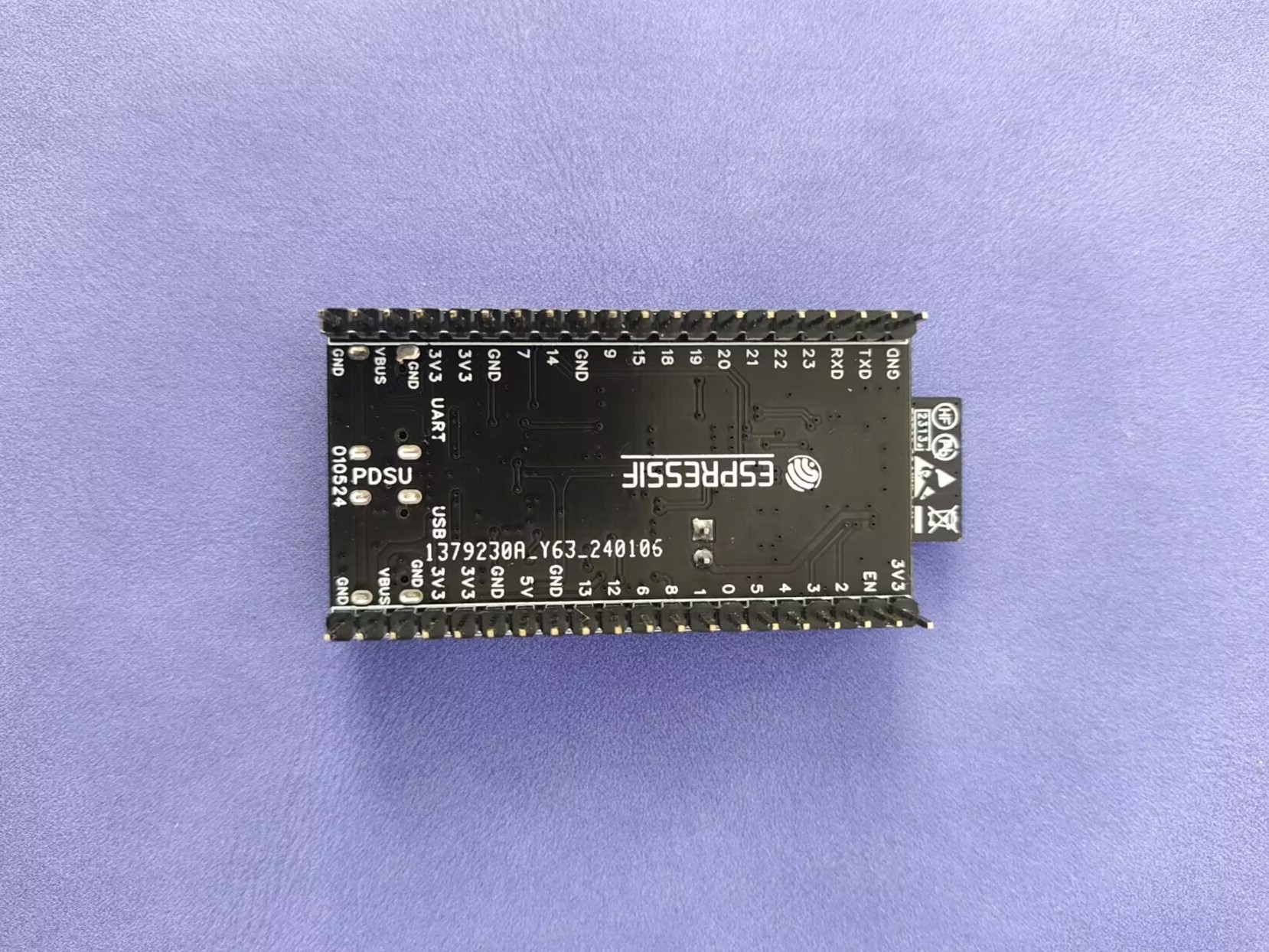
ESP32-C6-MINI Development Board
Referring to the official development board, Espressif's first SoC supporting Wi-Fi 6 integrates 2.4 GHz Wi-Fi 6, Bluetooth 5 (LE) and the 802.15.4 protocol.
1. Project Description:
This development board is only for testing program download; all other aspects are for testing.
It references the official development board, but has more power pins than the official board; it uses the CH340C chip; it includes an RTC pin; the left Type-C port is for the chip's USB port, and the right port is for UART, whereas the official board is the opposite.
2. Physical Sample Image
and Silkscreen Marking: PDSU: Pingdingshan University, 010524: Design completed on January 5th, 2024.
3. Other
Work: I've become lazy; I'll add more later when I have time.
PDF_ESP32-C6-MINI Development Board.zip
Altium_ESP32-C6-MINI Development Board.zip
PADS_ESP32-C6-MINI Development Board.zip
BOM_ESP32-C6-MINI Development Board.xlsx
94293
[FOC] Gimbal Motor Module
FOC controller using STM32G030F6P6
To learn the FOC algorithm, a single-motor integrated closed-loop module was redesigned, drawing inspiration from open-source projects. It includes an onboard encoder and current acquisition chip, enabling three-loop control: position, current, and speed.
This version is for learning and testing purposes only .
PDF_【FOC】Gimbal Motor Module.zip
Altium_【FOC】Gimbal Motor Module.zip
PADS_【FOC】Gimbal Motor Module.zip
BOM_【FOC】Gimbal Motor Module.xlsx
94294
electronic
 The actual product is as follows:
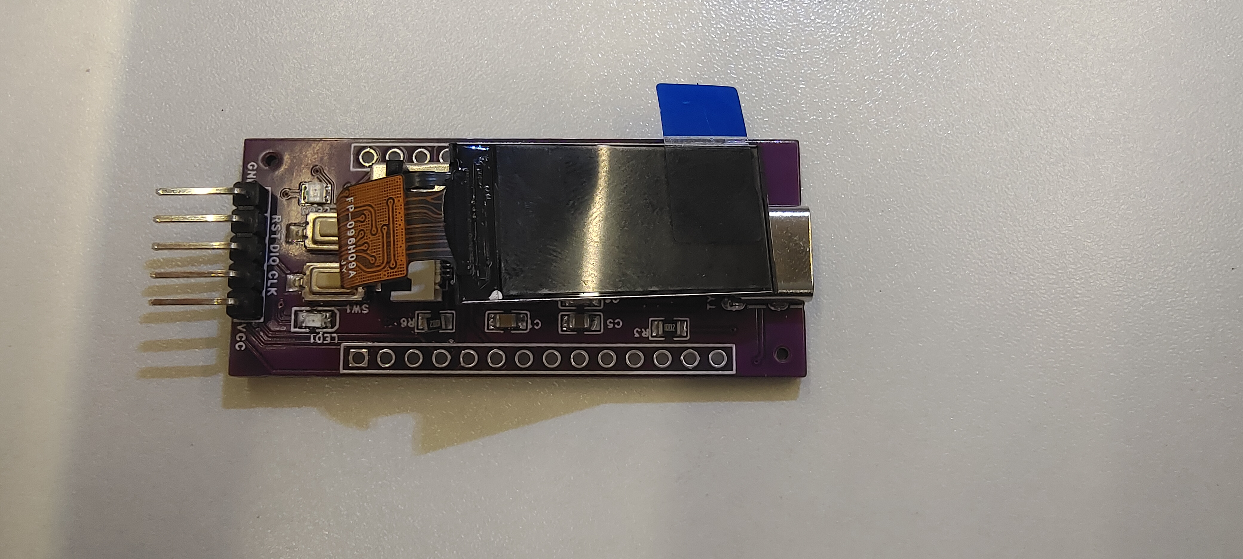


 京公网安备 11010802033920号

 68658-419LF


