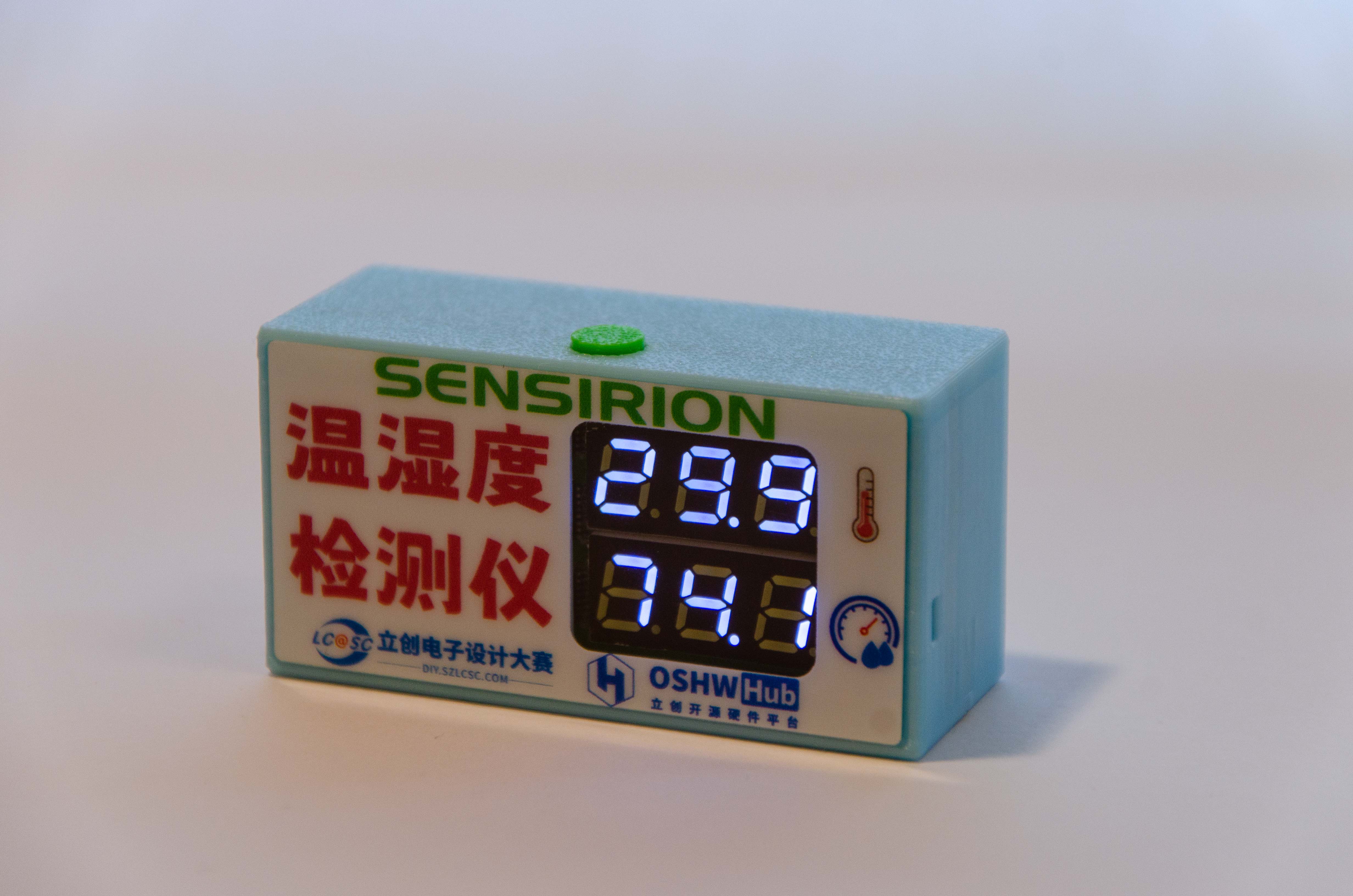
1. Project Function Introduction
This desktop temperature and humidity meter project in the training camp uses the STM32G030K6T6 chip as the main control chip. This chip uses an Arm Cortex-M0+ core with a maximum clock speed of 64MHz.
It has 32KB of Flash and 8K of SRAM, and the power supply voltage is between 2.0V and 3.6V.
Basic code generation and configuration can be performed using this chip through the STM32CubeMX software. The graphical interface allows for quick and easy use of the chip, which is very user-friendly for beginners like myself.
This temperature and humidity meter can achieve high-precision temperature and humidity detection and operates in a low-power mode, saving energy.
2. Hardware Section:
2-1 Overall Schematic Design:

Project Overall Schematic
2-2 Main Control Circuit:

The main control MCU
circuit is powered by the ferrite bead in L1 and capacitor C2, achieving filtering to ensure a clean power supply for the MCU. The peripheral pin connections of the main control MCU should follow the pin definitions in the product manual. It is important to note that pins with specific functions should be used for their designated functions. For example, if the sensor connection requires the I²C function, then a pin with the I²C function should be used. This facilitates future pin usage.
2-3 Crystal Oscillator Circuit:
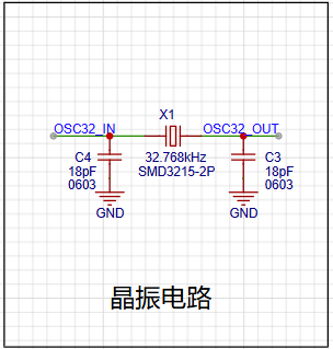
The crystal oscillator circuit
uses a 32.768kHz clock crystal to provide timing for the RTC, enabling the temperature and humidity detector to have a timing function, facilitating future functional expansion.
2-4 Temperature and Humidity Sensor Circuit: The core component of this project is the SHT40 temperature

and humidity sensor module
. The SHT40 is a fourth-generation, high-precision, ultra-low-power 16-bit relative humidity and temperature sensor manufactured by Sensirion. Its main characteristics are: relative humidity accuracy of ±1.5%RH, temperature accuracy of ±0.1℃, average operating current of 0.4μA, idle current of 80nA, and operating range of 0-100%RH, -40-125℃, meeting daily temperature and humidity measurement needs.
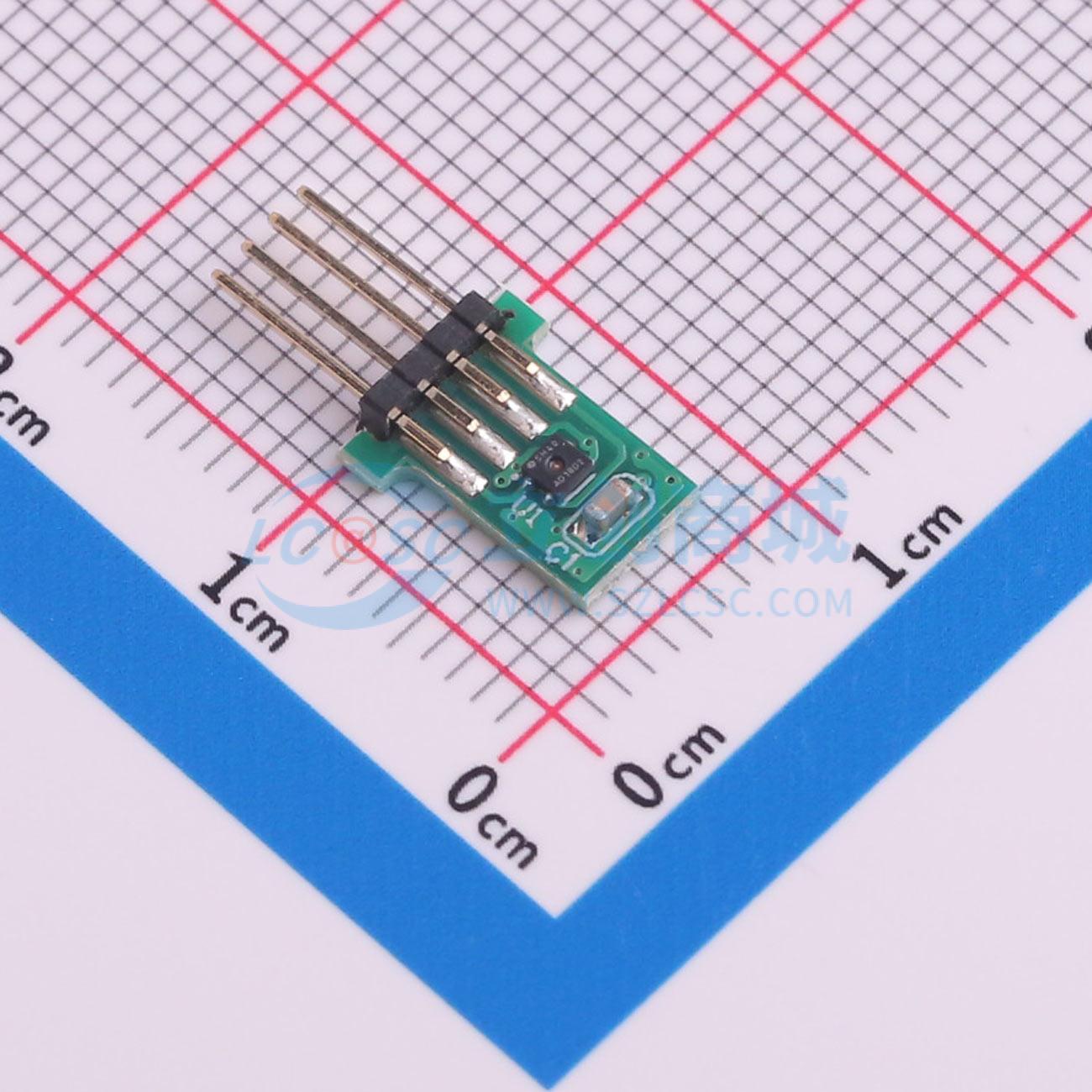
Because
the SHT40 is very small and difficult to solder, the SHT40 module specifically provided for this competition was used for ease of use. A crucial point to note is that the pins and sockets of the SHT40 temperature and humidity module must be correctly connected. Incorrect connection can affect measurement accuracy or even burn out the module!
2-5 Tri-state Output 8-bit Shift Register Circuit: To illuminate multiple digital tubes, an SN74HC595PWR
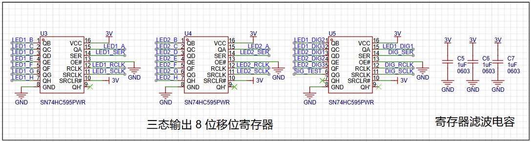
register is used to connect to the digital tubes for display. Multiple LEDs on the LED digital tube can be controlled via a single pin of the MCU
. It's important to note that if the digital tube display is incomplete or malfunctioning during later soldering, it's highly likely due to solder bridging or improper soldering of the register pins. Resoldering and checking the pin connections are necessary.
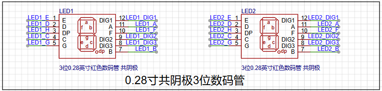
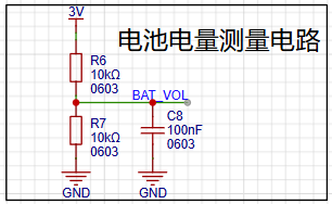
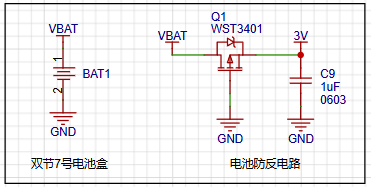
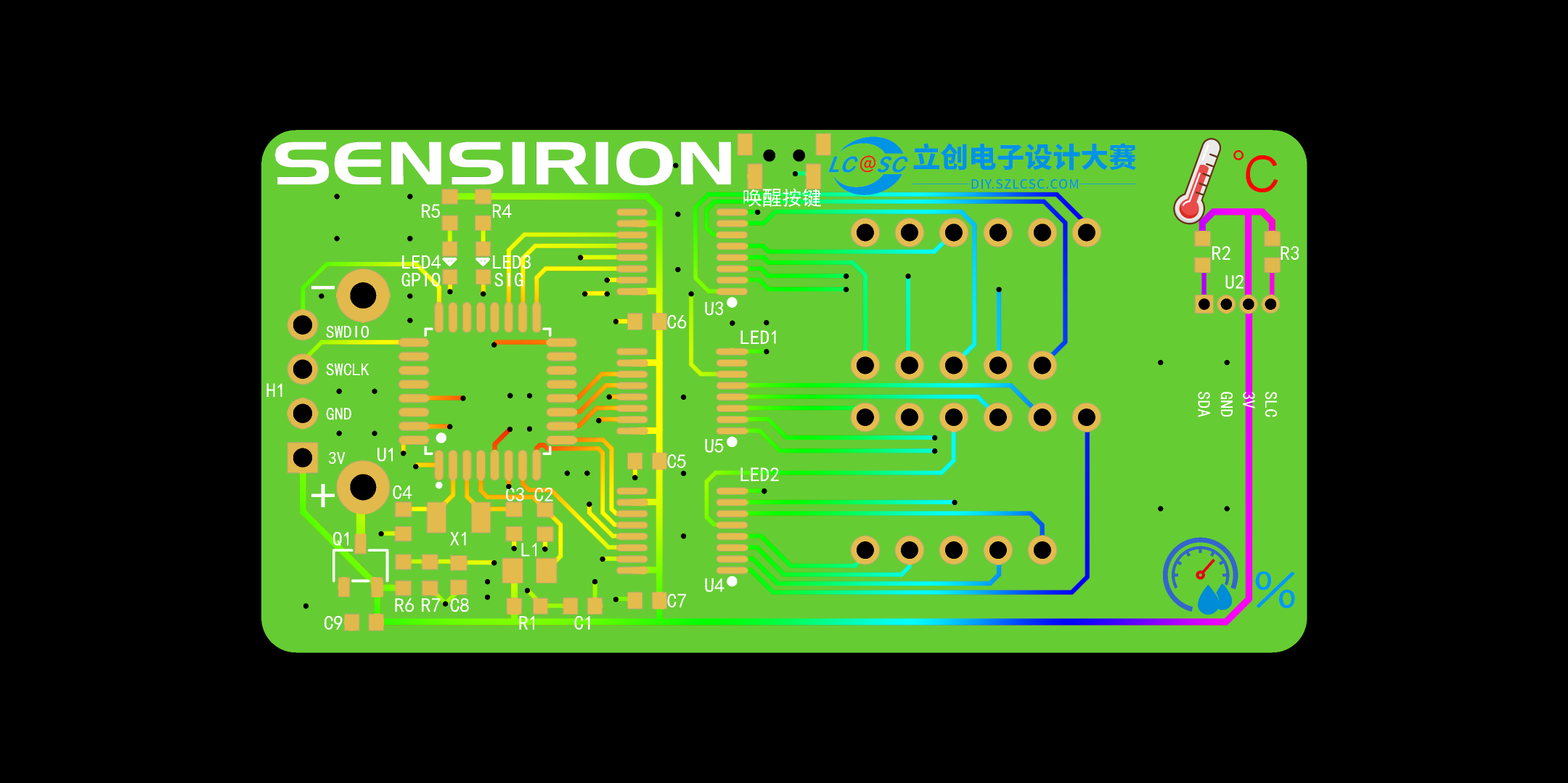
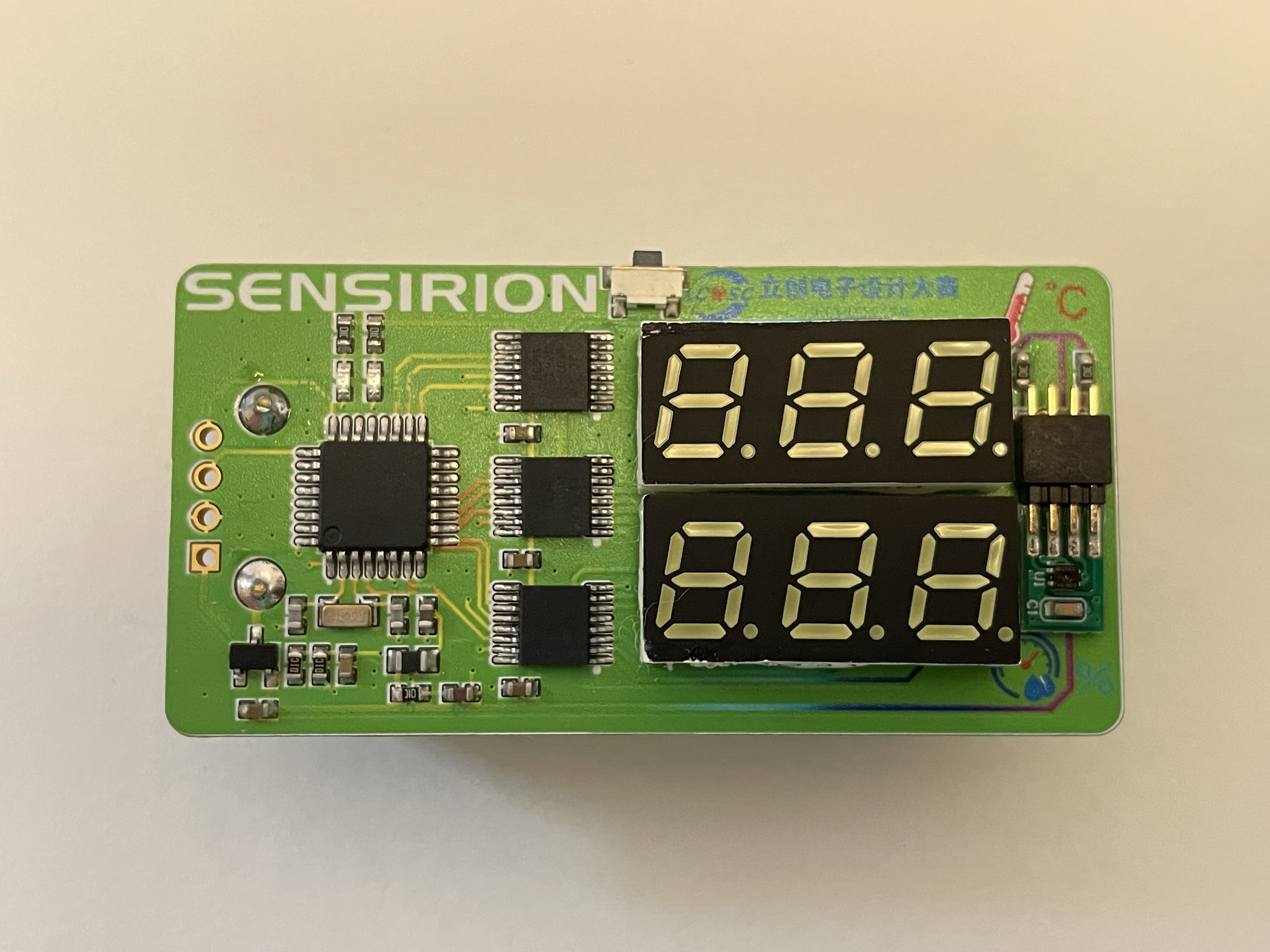
2-6 Wake-up Button Circuit: To achieve low power consumption and energy-efficient long-term operation of the temperature and humidity detector, a dedicated wake-up button is used. This allows the device to be woken up when temperature and humidity display is needed, and enters a low-power standby state when not in use. The button should be placed near the edge of the board for easy access. 2-7 Test LED Circuit : To facilitate later software debugging, two LEDs are used for testing and debugging of the software code. 2-8 Digital Tube Circuit: This circuit uses two 0.28-inch common-cathode 3-digit digital tubes to display temperature and humidity respectively. The LEDs come in various colors, which can be selected according to preference. 2-9 Battery Power Measurement Circuit: This circuit measures the battery voltage by collecting data, providing an extension function for displaying the battery level later. However, a reference voltage is needed for the MCU to compare the measured power level. Since there is no standard reference for comparison, the power measurement is inaccurate. For more accurate power measurement, consider replacing the MCU with one that has a built-in reference voltage ADC. 2-10 Battery Circuit: The battery power supply section uses two AAA batteries to power the entire system. To prevent reverse connection damage to the I/O ports, a WST3401 is used for reverse connection protection, protecting the chip's I/O ports. 2-11 Debugging Interface: This circuit uses an external SWD debugging interface for software debugging of the entire project. It's important to note that for easier installation of the casing later, this 1x4p header doesn't need to be soldered; it can be held in place by a programmer for downloading and burning code. 3. PCB Display 3-1 PCB Overall Layout and Routing The overall layout is compact, with all resistors and capacitors using the small 6030 package, further reducing the board size. 3-2 PCB 2D View PCB Front View PCB Back View This PCB was manufactured using JLCPCB's color silkscreen printing process, providing a more attractive appearance. The overall PCB uses Sensory's signature green as the main color, accented with JLCPCB's blue, making it more eye-catching and beautiful. The PCB traces are also drawn using a color gradient, giving the board a more technological feel and clearly showing the connections between components, facilitating measurement of pin soldering during later soldering. There was a small hiccup here: initially, the component silkscreen was changed to green, the same color scheme as the board, which made it visible on the screen, but difficult to see in the actual printed result. So, I changed the component silkscreen back to white for easier soldering. 3-2 PCB 3D View PCB Front View PCB Back View One point to note here is that the 4P header of H1 can be left unsoldered, which makes it easier to install the casing later. You can use a programming clip or other methods to connect to the debugging interface for downloading and debugging. 3-3 PCB Soldering Completed Object View PCB Front View When soldering the power socket on the back, you can use a sponge strip to pad the base, which will make the battery holder fit more flatly on the PCB. Back Sponge Strip Diagram 4. Software Part 4-1 Software Preparation The software part uses STM32CubeMX software to generate the basic framework. When using STM32CubeMX software, you need to register an account before you can install and download the software. Basic Usage of STM32CubeMX Software Log in to your account first to use the software .


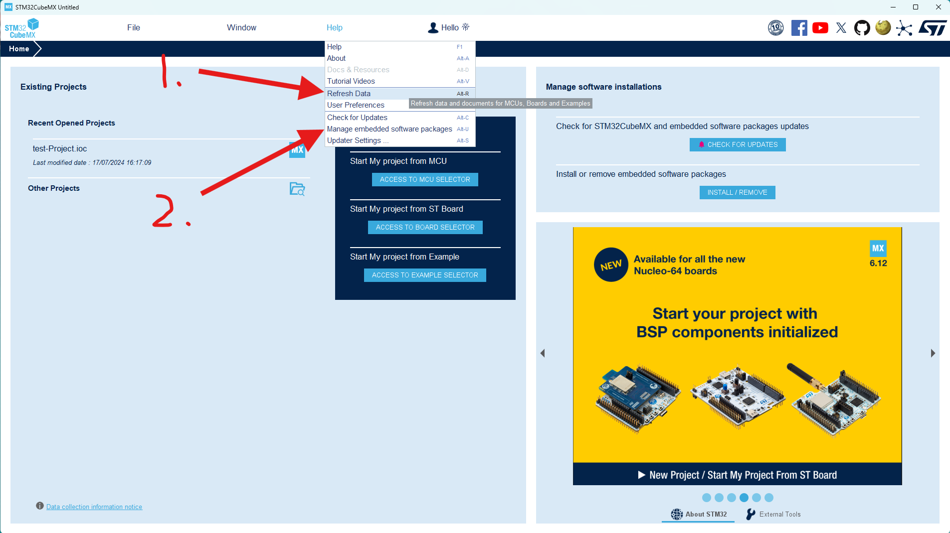
After logging into your account, first click the "Update Data" option under "Help" to ensure the software data is up-to-date, then click "2. Manage Firmware Packages".

Scroll through the list to find the STM32G0 series firmware package you're using and select the latest version to install.

Click "New Project" to begin creating our software code project.
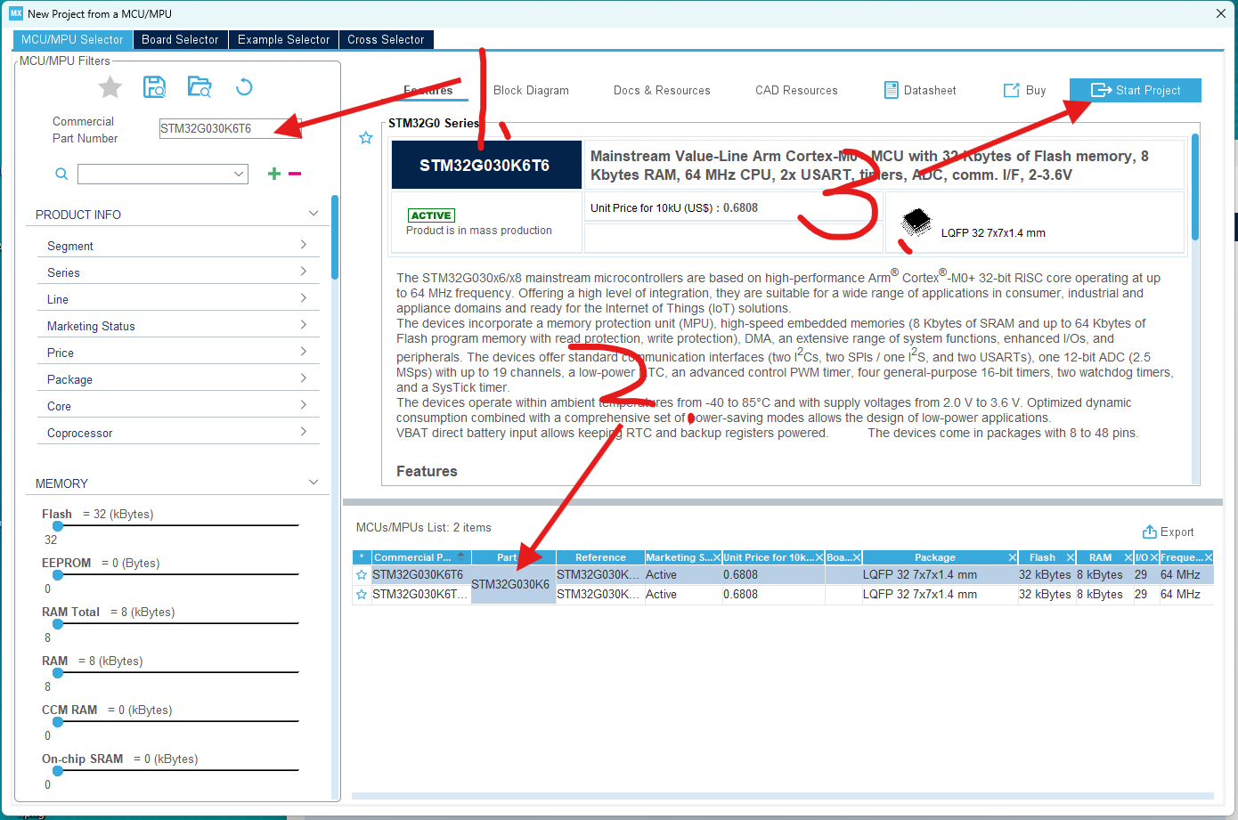
In the pop-up project window, select the STM32G030K6T6 chip you're using and create the project directly.
This completes the project creation. We'll then configure and call the chip's parameters within the newly created project.
4-2 Code Modification:
The code directly uses Chen's instructions, only modifying the button wake-up function.
Specific code modifications:
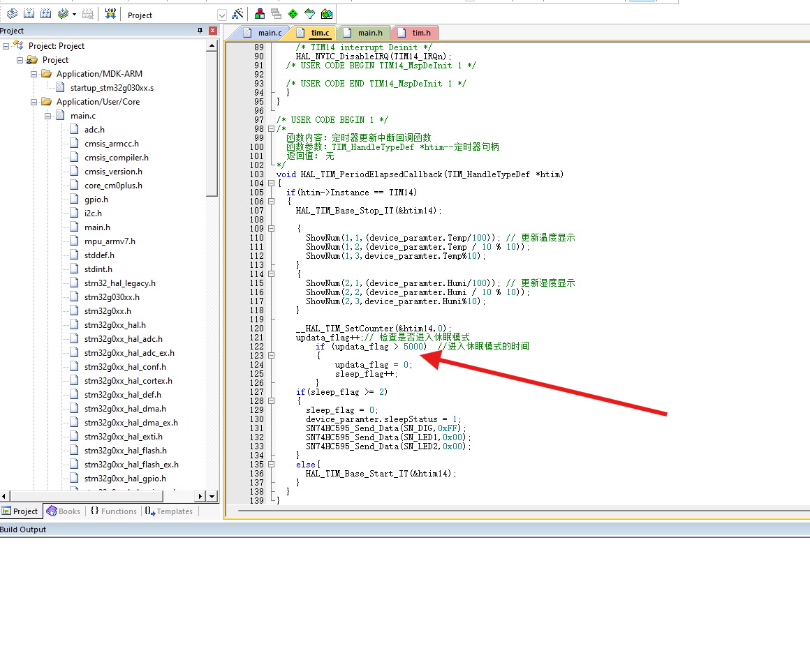
To display both temperature and humidity values simultaneously on the digital tube, we need to adjust the logic in the interrupt service routine so that the temperature and humidity display is updated with each interrupt, instead of alternating between them.
In this version, I made the following changes:
The conditional judgment for switching temperature and humidity displays using `updata_flag` was removed; instead, the temperature and humidity display is updated every time the interrupt service routine is triggered.
The logic for controlling the sleep mode using `update_flag` and `sleep_flag` is retained, but `update_flag` is no longer used in the display update section.
After this modification, the temperature and humidity values will be displayed on the digital tube every time there is an interruption, instead of alternating between displays.
The duration of the digital tube display can also be modified, allowing you to choose how long the digital tube should remain lit before entering sleep mode. I set it to enter sleep mode 5 seconds after the digital tube lights up. Regarding
the code burning in section 4-3, I used
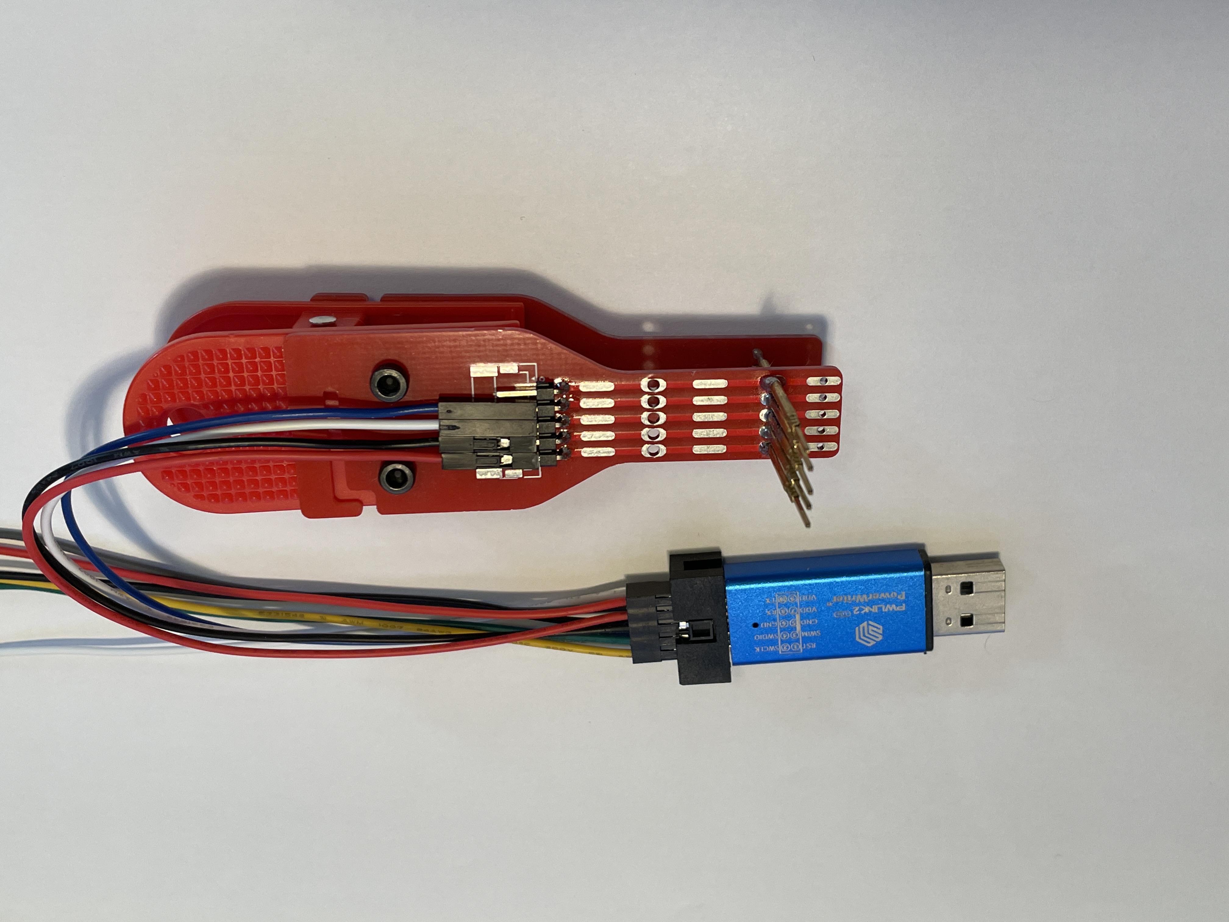
the PWLINK2 programmer and the programming clip.
The programmer I used is the PWLINK2, which is inexpensive and supports a wide range of chips. You can also use DAP Link or STLink if you have them. I only
used the PWLINK programmer here because I only had the PWLINK programmer. The programming clip is used here for easy placement into the casing later. The link to make the programming clip is here: Compatible Multi-Version Test Clip, Probe Clip, Programming Clip, Download Clip - JLCPCB EDA Open Source Hardware Platform (oshwhub.com). Using the programming clip is very convenient.
Points to note when programming: The first time you program the code, it will program directly. However, the second time you try to program, it might tell you that the board cannot be detected because the MCU has entered sleep mode. You need to wake it up by pressing a button before you can program the code.
Another issue I encountered when using PWLINK is that the following window pops up during programming. Follow the troubleshooting steps in

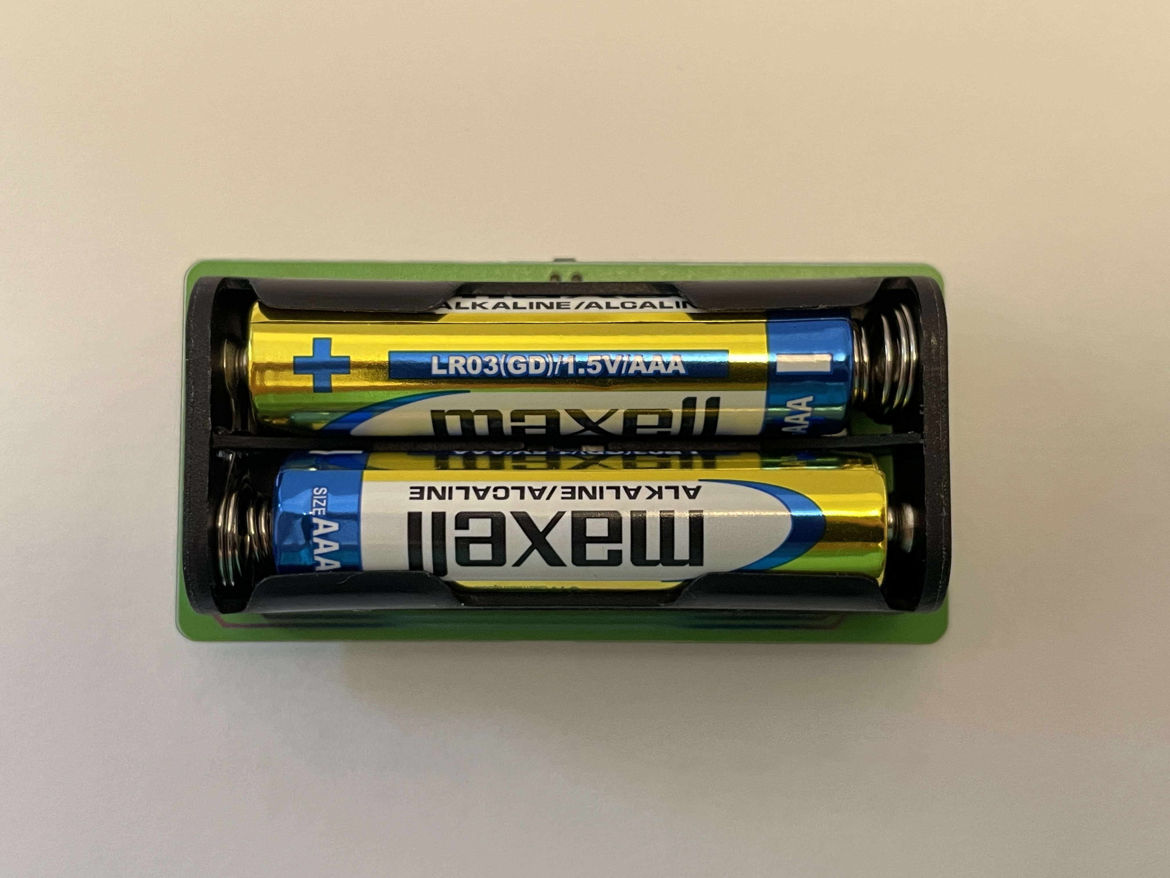
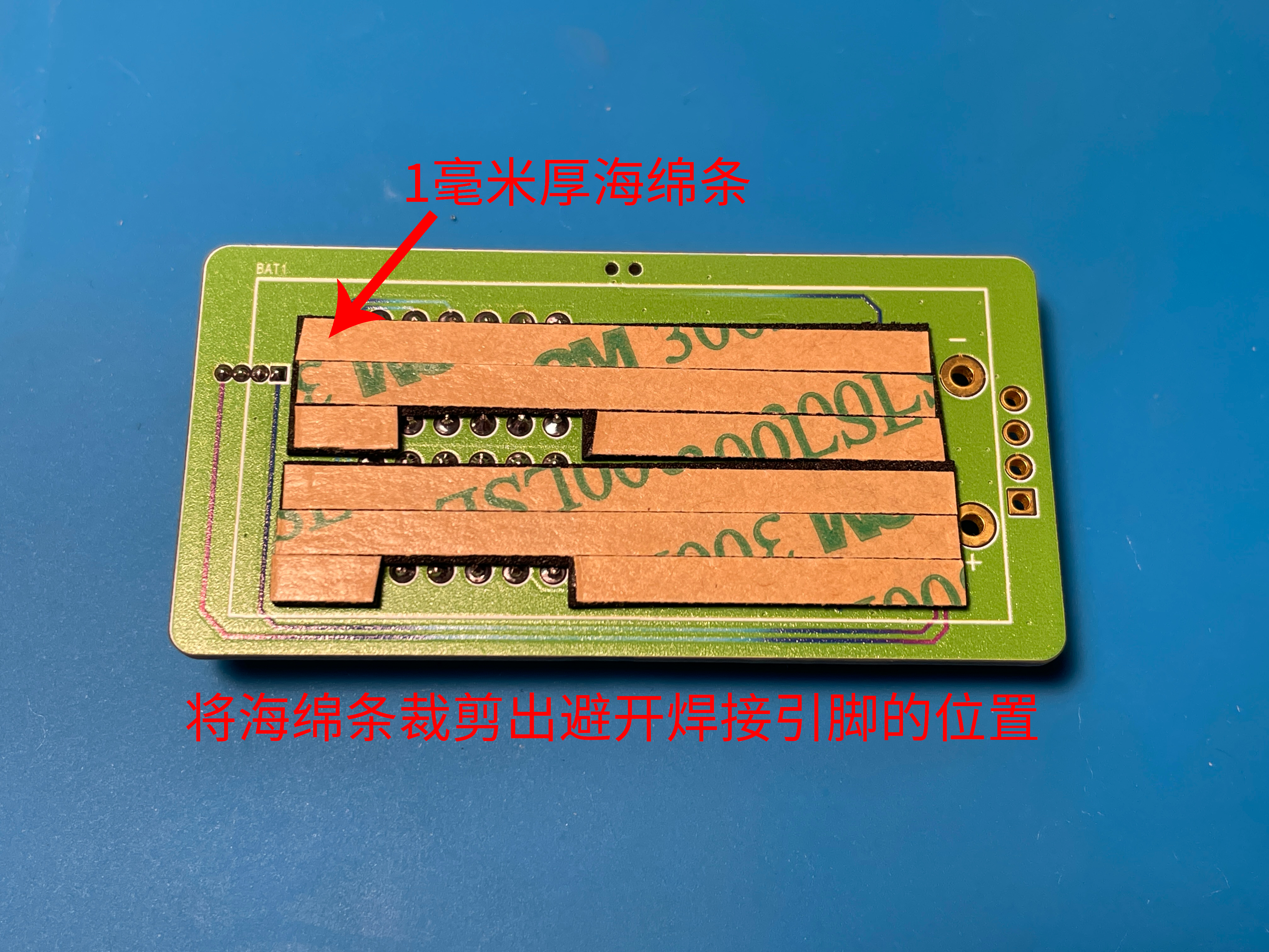
the pop-up window to resolve the issue, and you should be able to download normally. 5. Shell Part: Shell rendering image, actual product image, overall assembly diagram. The shell uses an embedded installation mode, with the PCB inserted through slots on the left and right sides. This avoids installing screws on the PCB, thus reducing the overall size of the PCB and making the finished product compact and aesthetically pleasing. The bottom plate of the shell is fixed to the top of the shell with two M2 screws. The top of the shell has a pre-drilled hole for an M2 heat-fused nut, which can be directly pressed into the hole without heat fusing (because the pre-drilled size is a bit large, haha). A hole is also made on the top of the shell to accommodate the wake-up button. Four simple panel designs were provided, and the files are included in the PCB design files. You can modify them to your liking. I chose PET material, printed on the bottom, with a thickness of 0.125mm. I didn't use adhesive backing because I didn't receive panel coupons this time, so I applied double-sided tape myself to save money; the effect is the same. 6. Competition LOGO verification PCB front PCB back 7. Project assembly demonstration video


 京公网安备 11010802033920号

 XC6204B69BDL


