
The flickering and ghosting issues are due to compression of videos and photos; they won't appear in real-world viewing. For
actual effects, please refer to the initial GIF (below) or video

. ▎Update Plan
√ June 27, 2024: Release open-source PCB project [Control Board 4.0.4 cost reduction] [Power Board 2.8.5 cost reduction] Upload
open-source project + source code (without alarm clock)
Release firmware 20240627A Upgrade program
open-source shell STL, STP files
√ July 3, 2024: Upload Taobao BOM, LCSC BOM
⚫ July 10, 2024: Upload SOP workbook (not updated, as no one has replicated it, so it's been shelved)
Cost
: LCSC order: ¥200+ = ¥150+¥10 (shipping)+¥30 (buy battery, OLED, RTC battery, vibration switch, FFC cable on Taobao)+¥12 (3D shell + shipping)
Taobao order: ¥120+ =109+12 (3D shell + shipping)
Get materials from the author: ¥70 = 52 (average quantity and shipping) + 9 (average shipping for 3D shell) + 10 shipping.
The
third batch of 16 clocks in this project is under construction. Too many people have asked about it, I'm simply too busy to keep up. I haven't dared to update the project or reply to messages. I haven't dared to say anything
because so many people have left messages or sent me private messages expressing their desire. Also, this project is quite difficult to solder, and I feel very sad seeing others in the group failing to complete theirs. If you really want one, you can send me a private message (read the following carefully). 63 including shipping, I'm losing money on the shell to make friends, but the delivery time may be a little longer. The author is working like a slave and needs some time to complete it.
The QQ group
is basically inactive, hardly anyone talks. Group number: 427651038.
Project demonstration video
: Reduced version feature demonstration and power consumption demonstration: https://www.bilibili.com/video/BV1hZ421g7mz
Project description:
This project is based on [24-day constant light]. Low-Power Mini Desktop Clock (https://oshwhub.com/yq-qvq/low-power-consumption-for-24-days-desktop-clock) This project represents a significant cost-reduction improvement to the previous model. The current batch cost is approximately ¥50+, but the cost per unit will increase due to the inability to share shipping costs.
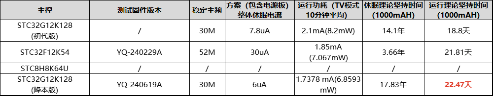
This project is a low-power desktop clock based on the legendary 32-bit 51 microcontroller STC32G12K128 chip as the main controller, operating at 5V... At 255 brightness in TV mode (factory default setting), the average power consumption is 1.7378mA (6.8593mW), and it can run for about 24 days. It is equipped with RTC, temperature and humidity, magnetic intensity, acceleration, air pressure and light intensity sensors for development.
Note that
this project is powered by a soft-pack lithium battery. Please pay attention to safety when using it. Do not leave it unattended while charging to avoid physical damage to the battery. Avoid overcharging, over-discharging and short circuits. Avoid placing it in harsh environments such as high temperature or low temperature.
Screen burn-in issue:
This project uses an OLED screen. If a certain pixel is lit for a long time, light decay will occur, resulting in a "mark" on the screen. The image below shows the screen burn-in situation after 6-7 months of use. The horizontal line is the camera shooting problem. You can see that the mark is left in the frequently displayed area, but it is almost invisible when displaying the time interface, unless you enter the menu or a pure white screen.
Therefore, the screen is essentially a consumable item and can be replaced every year or year and a half. If you mind this, please do not copy or purchase.

Project changes:
OLED screen communication has been changed from SPI to I8080 bus;
logic power supply has been reduced from 2.8V to 2.7V;
surface mount resistors and capacitors have been changed from 0402 to 0603; tactile switches, FFC sockets, and RTC batteries have all been replaced; capacitors are now uniformly MLCCs; PCB layout has been rearranged; pins have been adjusted; the reset button has been moved below the screen; all underlying drivers have been modified accordingly; the step
-down chip has been changed from TPS62740DSSR to ETA3425S2F;
the fuse and lithium battery protection chip ME4211AM6 have been removed; and the system is now entirely reliant on a soft-pack battery. The battery protection board was modified to
remove the 4K square wave generation circuit and replace it with a microcontroller PWM port direct drive for tone and volume adjustment.
The CH340 was removed and replaced with USB direct download.
The RTC package was increased for compatibility with the DS3231MZ
light intensity meter. The original BH1745 was replaced with an OPT3001.
The casing was redesigned.
The MCU was changed from an STC32F12K54 to an STC32G12K128. Although the speed decreased, the flash memory was doubled, resolving the issue of the 32F being full.
The OLED contrast current reference resistor was removed and replaced with an internal reference, but the pads were retained.
The issue of long-waiting tasks causing congestion in the program framework was fixed.
Project hardware resources
: ● Main controller: STC32G12K128
● 1.3-inch OLED: SSD1315
● Thermometer and hygrometer: SHT40
● Barometer: SPL-06
● RTC: INS5699 (with reserved DS3231MZ package)
● Light intensity meter: OPT3001
● Magnetometer + accelerometer: BMC050
● Buzzer
● Vibration Switch
● Buttons X5: +, -, OK, Exit, Reset
Project History
2020-September
: Project Conception Begins
2020-11-18:
Prototype 2.0 version power management board, soldered and tested
2020-12-16:
Prototype 2.0 version core board, soldered and tested 2020-12-25
: Prototype 2.0 version sensor board, soldered and tested
2021-01-02: Prototype 2.0 version core board, soldered
and tested , code writing completed 2021-01-14: Prototype 2.0 version core board, soldered and tested 2021-01-17: Prototype 2.0 version core board, soldered and tested 2022-June
Started conceptualizing a low-power UI framework and used a development board to verify the basic program framework (where the dream began).
October 18, 2022:
Prototyped the 4.0 power board (completely redesigned), and soldered and tested.
December 6, 2022
: Prototyped and iterated the 4.0 power board, and soldered and tested.
Prototyped the 4.0 control board (integrating the 2.0 core board + 2.0 sensor board), and soldered, programmed, and tested
. Design, verification, and completion began. Optimized task stack push and pop, fast batch loading, main menu, second-level menu, third-level menu, etc.
Started studying English manuals, writing sensor drivers,
and getting engrossed in Minecraft with friends.
October 10, 2023:
Prototype iteration 4.0 power board, soldered and tested.
October 19 , 2023 : Prototype iteration 4.0 power board
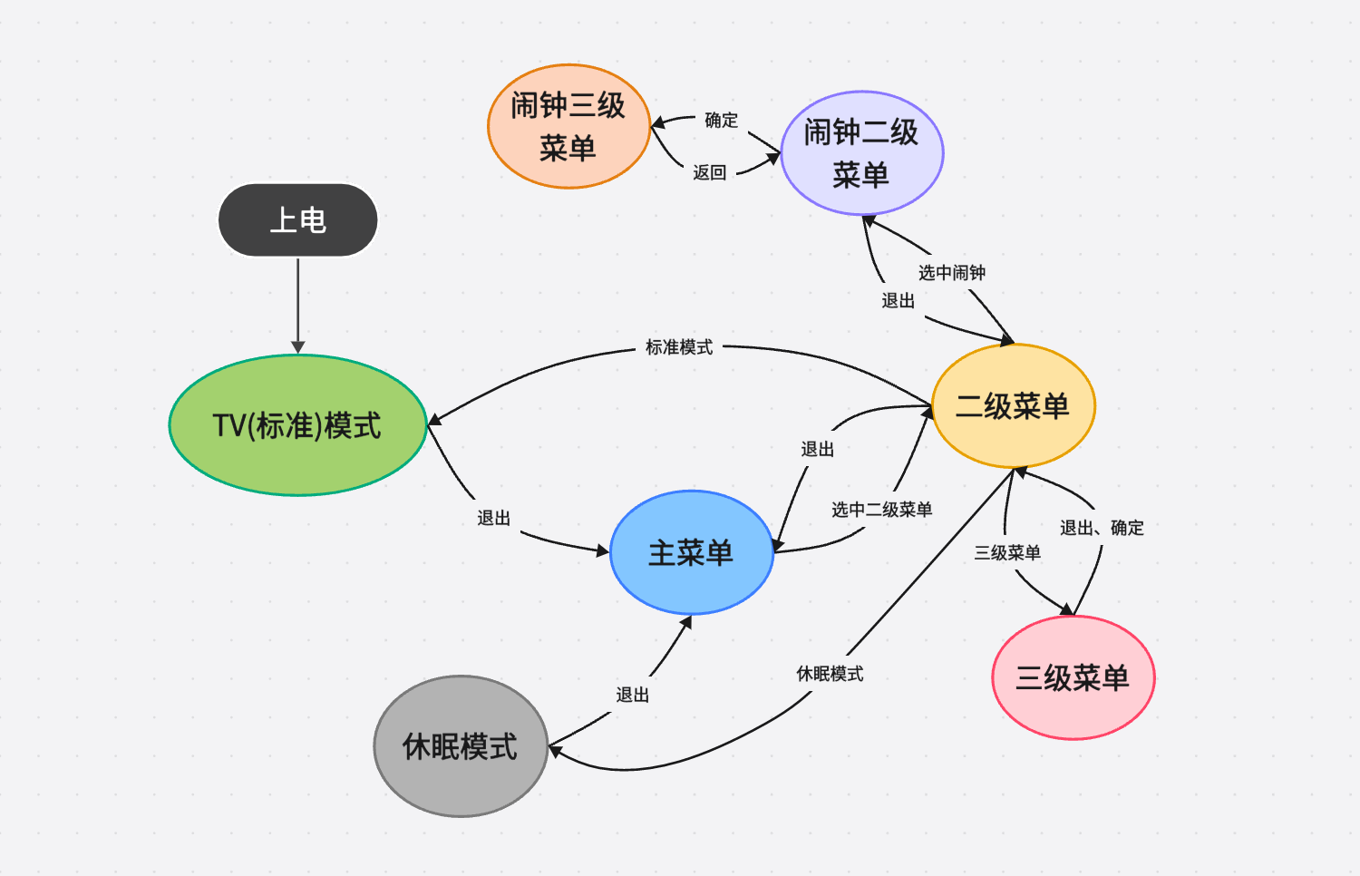
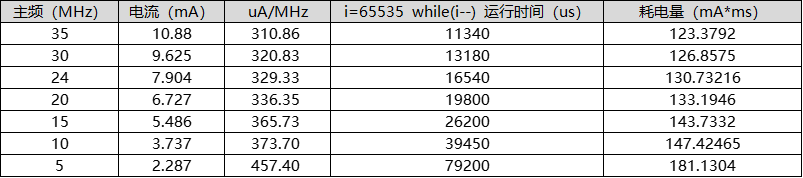
, soldered and tested. October 23, 2023: Prototype iteration 4.0 power board (Yutai solution), soldered and tested . October 27, 2023: Prototype iteration 4.0 power board (Texas Instruments solution), soldered and tested . December 25, 2023 : Prototype iteration 4.0 power board (Texas Instruments solution 2), soldered and tested. January 16, 2024: Prototype iteration 4.0 power board V2.8.4 (Texas Instruments solution), soldered and tested. January 25, 2024: Released on LCSC Open Source Community . January 26, 2024: Prototype iteration 4.0 control board (I8080 bus solution), soldered, programmed, and tested. March 6, 2024 : Prototype iteration 4.0 power board V2.8.5. Soldering and testing were performed on the following projects: March 14, 2024: Prototype Iteration 4.0 Control Board V4.04 (SPI solution); April 29, 2024 : Prototype Iteration 4.0 Control Board (I8080 bus solution 2); May 5, 2024 : Newly designed 4.0 Power Board V2.8.5 (cost reduction); June 1, 2024: Iteration design 4.0 Power Board V2.8.5 (cost reduction 2); Newly designed 4.0 Control Board V4.0.4 (cost reduction I8080 bus solution); June 23, 2024: Attempt to fix the issue of long-waiting task requests causing blocking in the program framework; currently under testing, no abnormal power consumption has been observed . Testing was conducted using a Hezhou CC meter under factory initial settings (OLED). The 5V 255W brightness version uses 3.84V battery power (the downgraded version uses 3.94V battery power, but automatic dimming is off). At full brightness (5V), it can last for 22 days. With automatic dimming enabled, it can last even longer, over 24 days. UI display : Main menu (scrolling 3.94V 2.5mA) : Secondary menu (scrolling 3.94V 4.3mA) : Tertiary menu: TV mode (clock display): TV mode (ambient display): TV mode (power display): Sleep mode: Compass UI: UI operation logic: Low power consumption approach. Those familiar with PCs know that computers generally consume less power when idle because the CPU is downclocked, in a "idling" state. Similarly, most people use downclocking to reduce device power consumption. Many people ask why I don't downclock when I use a 30MHz CPU. Indiscriminately downclocking, regardless of the situation, will actually increase device power consumption. The following graph tests the operating current of the STC32G12K128 microcontroller at various clock frequencies. I measured the time required for the microcontroller to run 65535 `while(i--)` cycles at each clock frequency. This is to demonstrate that when a microcontroller processes a fixed amount of work, the time required is inversely proportional to the clock frequency. A 35MHz clock frequency is 7 times that of a 5MHz clock frequency, so the time required to process a task at a 5MHz clock frequency should also be 7 times that at a 35MHz clock frequency. This is indeed the case: 79200/11340 = 6.984. However, the current consumed at a 5MHz clock frequency is not 1/7 (0.1428) of the current consumed at a 35MHz clock frequency, but rather 2.287/10.88 = 0.21. This shows that executing the same amount of work at a lower frequency consumes more power, meaning a higher uA/MHz. For UI refreshes required in this project, the dot matrix calculations for UI refreshes involve a fixed workload. A lower uA/MHz results in lower power consumption, so a high clock frequency is needed to execute these tasks or calculations. Once completed and no further tasks are needed, the system enters sleep mode. Regarding the software, some low-level configurations utilize STC's sample code, OLED initialization references code provided on Taobao, and the CORDIC algorithm for the inverse trigonometric function Atan references code from the Redstone Circuits forum. The remaining parts were developed independently. The program flowchart is shown below. It uses a task number stack and a task waiting time stack for task scheduling and execution. The intermediate waiting time is used to enter power-down mode for transition. The reason for such power saving is that the MCU doesn't perform unnecessary tasks; it only runs when there are tasks available and remains in sleep mode at other times. When developing the first and second generation clocks, we discovered that the MCU often experienced delays during task execution. For example, when scrolling numbers, shifting 32 pixels required 32 shifts, with a 6-millisecond interval between each shift. This resulted in 186ms of idle time (31 x 6 = 186ms), which is critical. If the refresh rate is only one second, 18.6% of the time is wasted waiting. Similarly, after sending a measurement command to a sensor, there's a waiting period before the measured value can be read. To address this MCU idleness, a power-down mode could be implemented to reduce power consumption. However, this introduces a new problem: how does the MCU know when it needs to wake up? Once in power-down mode, the main clock stops oscillating, effectively rendering it "asleep." Knowing when to resume normal operation becomes a significant challenge.


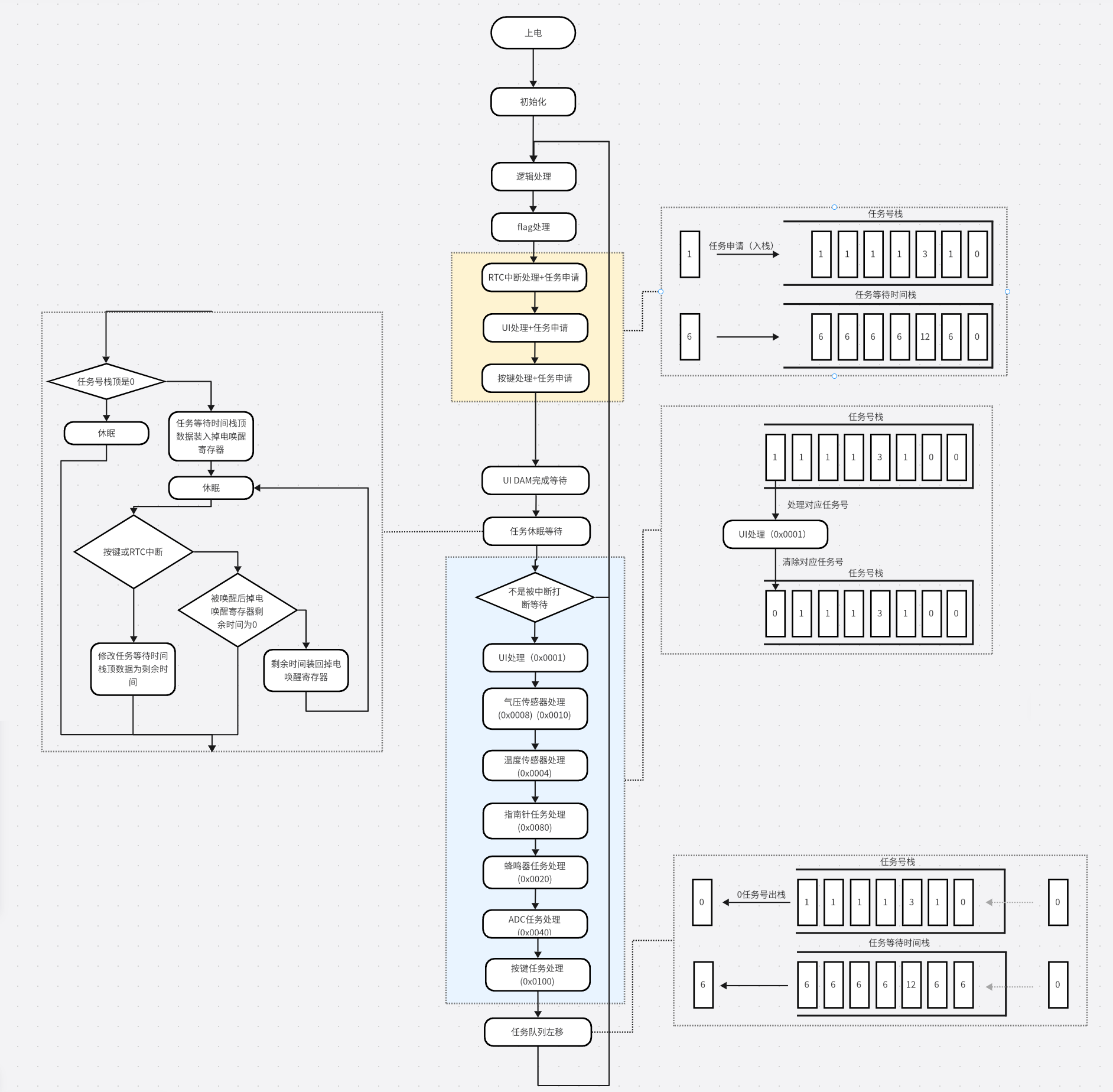
To address this issue, similar to how a worker can set an alarm clock, a power-down wake-up timer can be used. By setting the time of the power-down wake-up timer, the MCU can be controlled to wake up at the specified time after going into sleep mode. Then, we can take it a step further, for example, to shift 32 pixels, we would set 31
alarms. To do this, I introduced two arrays: a "sleep time array" and a "task number array" (each bit represents a task). The values of the two arrays correspond one-to-one. For example, to perform a 32-pixel shift, which needs to be performed 32 times, I first reserve 32 tasks in the "sleep time array" and the "task number array", as shown in the figure below.

Each time, the MCU checks the values in the "sleep time array" [0] and the "task number array" [0]. If they are not equal to 0, the value of the "sleep time array" [0] is loaded into the power-down wake-up register, and the MCU goes into sleep mode. After waking up, the corresponding task is matched according to the value of the "task number array" [0]. After the task is completed, the value of the entire array shifts one position to the left. When the values in the "sleep time array" [0] and "task number array" [0] are both 0, it indicates that the UI refresh task has been completed, the power-off wake-up register is closed, and the system has completely entered sleep mode, waiting for the external button to interrupt the task and wake it up.
However, there is not only one OLED screen refresh task in the project. For the sensor measurement waiting task, in order to ensure the timeliness as much as possible, it is impossible to measure it after the UI refresh is completed. Of course, we hope to do both at the same time. At this time, we need to write an insertion algorithm to insert the task into the task queue. For example, to insert a barometric pressure measurement task into the queue ("task number array" bit1 = 1), it is necessary to wait 15ms (6+6+3) and insert it into the queue in the figure above, as shown in the figure below. It can be seen that when the values cannot overlap, it is necessary to interrupt the queue to insert the value. 3 means that both bit0 and bit1 are 1.

For example, on the basis of the above, to insert another barometric pressure measurement task into the queue, it is necessary to wait 12ms and insert it into the queue in the figure above, as shown in the figure below. It can be seen that when the values overlap, it is not necessary to interrupt the queue to insert the value. It is only necessary to add the bit corresponding to the task number.

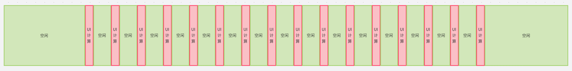
As described above, we know that when a microcontroller refreshes UI animations, it doesn't refresh continuously. There's always a certain interval between each pixel movement; otherwise, the movement would be too fast. For example, in the main menu mode, three 32x32 icons are displayed. The screen length is 128 pixels, and the icons are spaced 16 pixels apart. Therefore, to complete one scroll, it needs to translate 48 pixels, or 48 times. Assuming a 6ms wait between each movement, one translation takes 282ms (not including other execution time). If the microcontroller isn't doing anything else during this 282ms time, it's essentially idling. We can reduce power consumption by replacing this idling time with a sleep mode. This requires pushing the 48 UI refresh tasks (task number 0x0001) and the 6ms interval onto the task number stack and the task wait time stack, which are then processed by the task sleep waiting module. The microcontroller will then wake up from sleep 48 times at 6ms intervals, executing one UI refresh task each time.
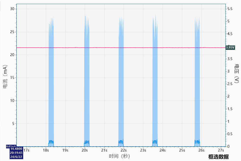
The following images are data collected from the test PCB. The test environment is a power board + test motherboard (only the FFC socket, MCU, and buttons are soldered). The test access points are the two ends of the battery output.
Since the MCU is powered by a step-down 2.7V supply, the actual 2.7V current should be converted by multiplying by 1.4. Of course, the battery is the final power source, so using the original data is also fine.
The while(1) test simulates the full operation of the microcontroller. The current can be seen to be around 7mA.
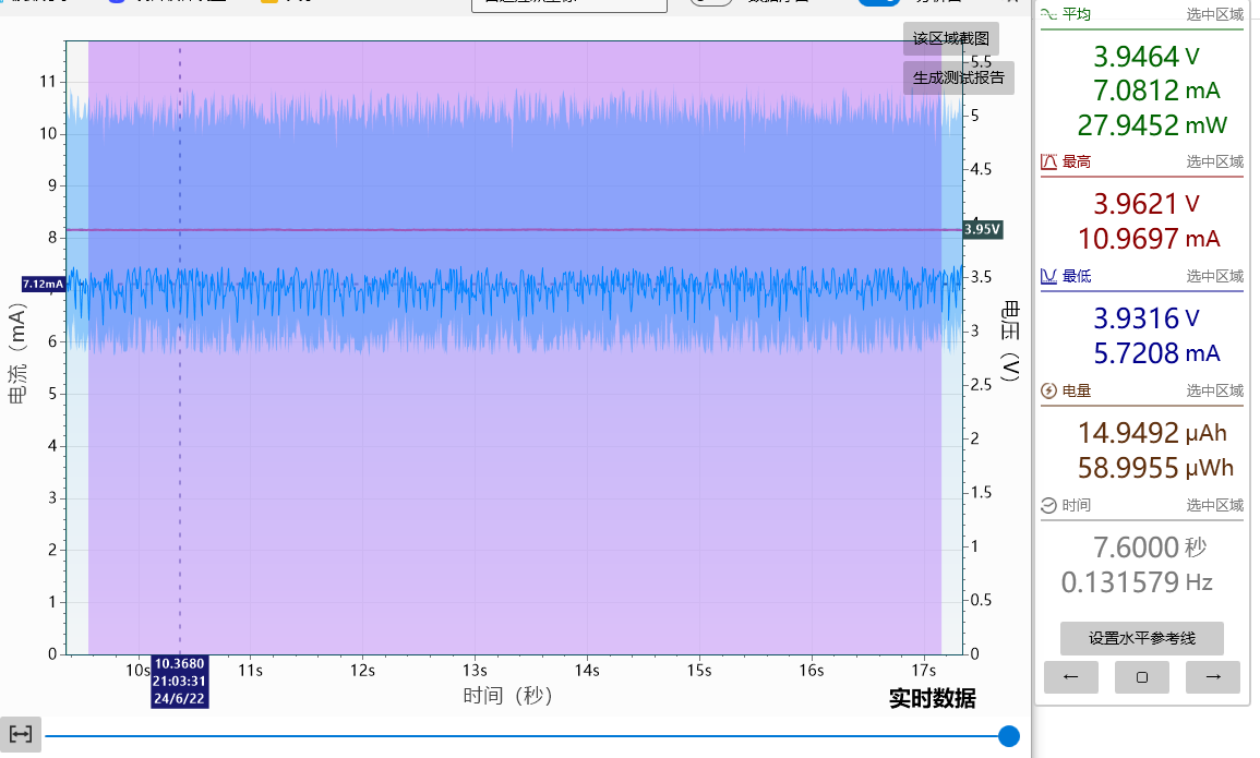
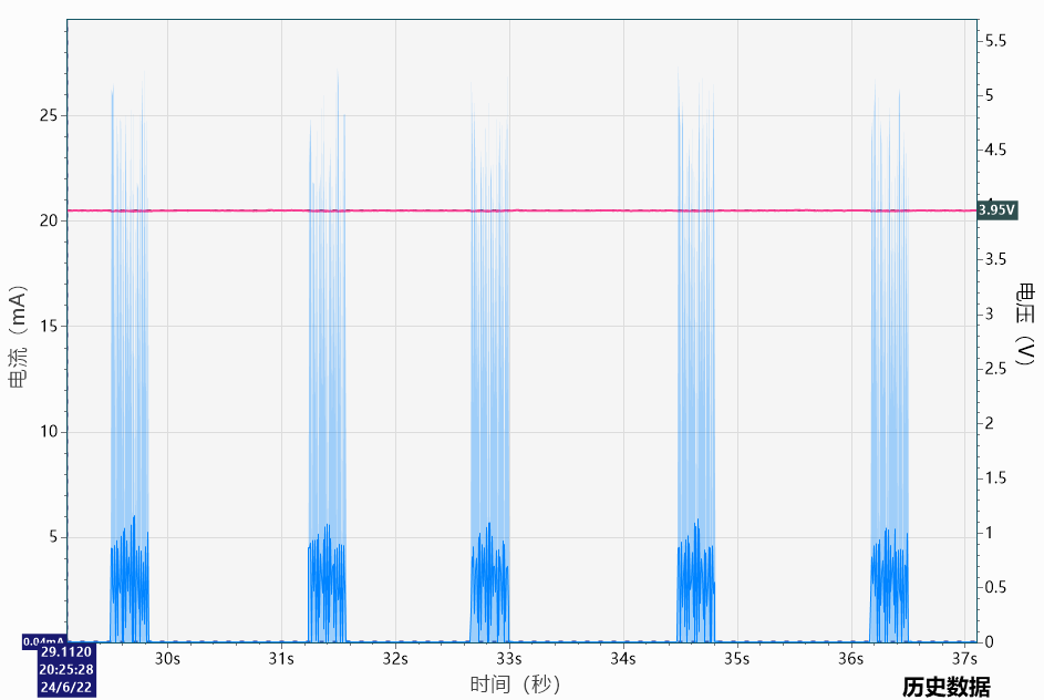
The main menu scrolling test moves the main menu UI once every 1-2 seconds. The average current is around 1mA. Zooming in, we can see that the current has 48 intervald spikes, indicating that the microcontroller works intermittently. The test involved 48 pixel movements, followed by a hibernation
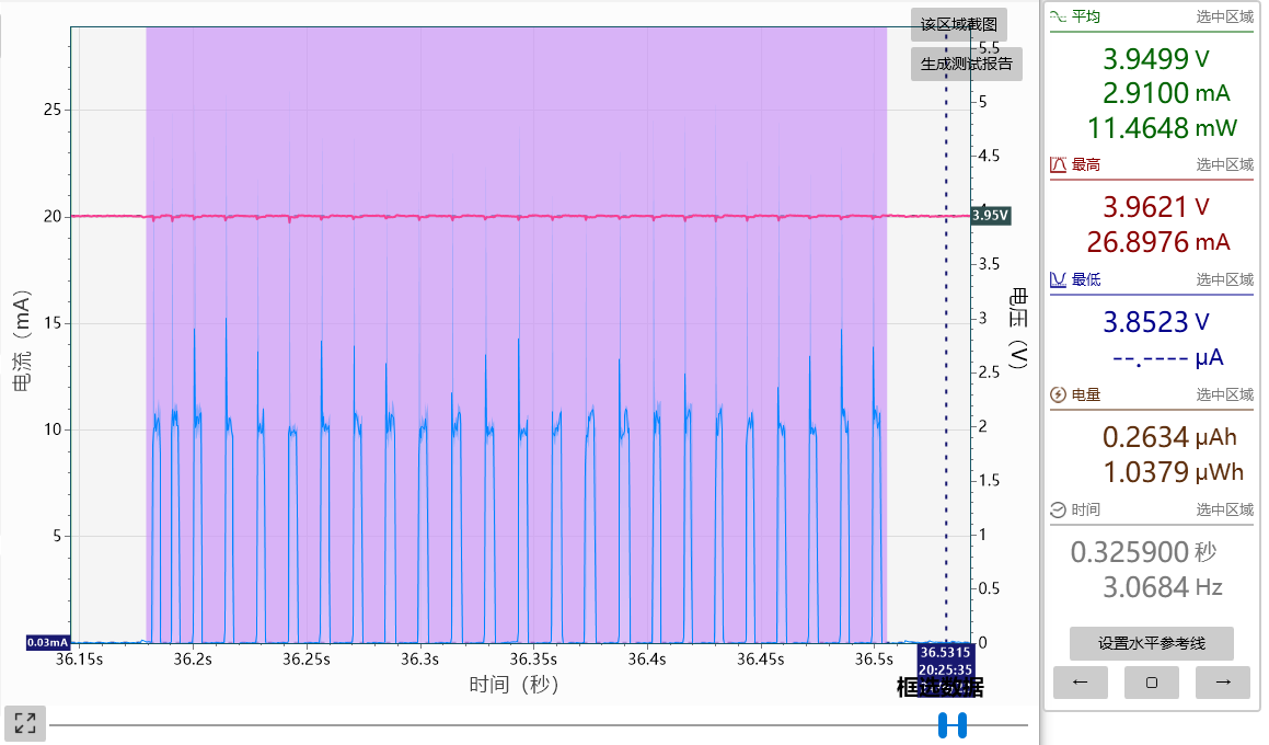
test of the secondary menu scrolling. The main menu UI was moved every 1-2 seconds. The average current was around 2.9mA. Zooming in, 24 spaced current spikes were observed, indicating the microcontroller intermittently worked 24 times, completing 24 pixel movements before returning to hibernation. Because more calculations were required than for the main menu movement, the current spikes had larger pulse widths, resulting in higher power consumption.
The previous code contained a serious bug in the framework: the queue-jumping algorithm. While a queue was being interrupted, the waiting submodules for the task to hibernate did not accept this, blocking the current task until it finished. This caused noticeable system congestion when waiting for tasks with long waiting times. For example, after enabling light control, ambient light data was acquired every second, with readings taken 200ms after each measurement. If the user was on the menu interface and waiting for sensor data, pressing a button would require waiting for the scheduled time to complete before UI scrolling could begin. Macroscopically, this manifested as intermittent stuttering after pressing the button. The correct behavior should be that when the button is pressed, if the submodule waiting for the task to sleep is currently sleeping for other tasks, it needs to be stopped, the remaining time is read back and filled into the top of the task waiting time stack, and then the task is inserted into the queue according to the source of the interrupt. After discovering this bug, no matter how I fixed it, it wouldn't work. Then, on the morning of June 24th, 2024, I made a random change and it actually fixed! Currently, no abnormalities have been found in testing.
Main hardware introduction:
MCU:
The MCU used in this design is the legendary 32-bit 51 STC32G12K128. Since I don't know how to use other series of microcontrollers, I had to choose this model. The maximum clock frequency is 35MHz, and the maximum stable clock frequency for this project is 30MHz. Exceeding this will cause random and inexplicable restarts. This problem bothered me for two weeks.
Power consumption is approximately 310uA/MHz, and the actual measured power consumption in sleep mode is around 2uA. The edge triggering of the IO port interrupt in power-down mode has a hardware problem; triggering one may trigger another, making it difficult to maintain.
Power supply: A 3.7V 1000mA soft-pack lithium battery is used for power supply.
The main circuit power supply
for the MCU, sensors, buzzer, and OLED logic is provided by an ETA3425. The power supply is provided by a DC-DC synchronous rectification buck converter, with the supply voltage set to 2.7V. This voltage is limited because it also needs to charge the RTC battery, so it cannot be reduced too much.

The OLED display's
built-in charge pump efficiency is extremely poor, so a DC-DC boost converter is recommended. Synchronous rectification boost is not recommended because its efficiency rarely exceeds 80%.
The OLED display power supply is provided by the MT3608L DC-DC asynchronous rectification boost converter, with selectable supply voltages of 5V, 6V, 7V, and 8V. The MCU controls the switching of the OLEDV1 (open-drain) and OLEDV2 (open-drain) pins.
The MT9700 is a current-limiting chip to prevent output short circuits.
OLEDV1 1 OLEDV2 1 5V
OLEDV1 0 OLEDV2
1 6V OLEDV1 1 OLEDV2 0 7V
OLEDV1 0 OLEDV2 0 8V
OLEDV1 (quasi-bidirectional) 1 OLEDV2 (quasi-bidirectional) 1 13V+ It was originally designed to have an isolated MOSFET, but this was later removed to reduce costs.
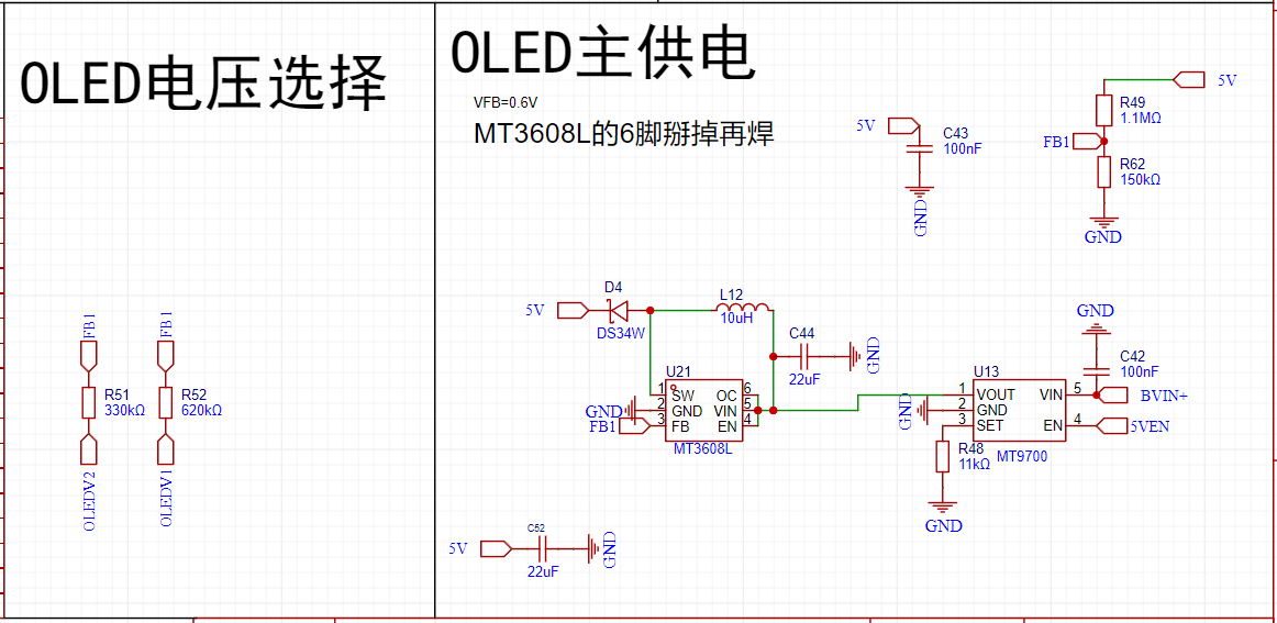
The MT3608L (72mV ripple) has a 10uf
output voltage (V).
Output Current (mA)
Output Power (mW)
Input Voltage (V)
Input Current (mA)
Input Power (mW)
Efficiency
5.018
1.521
7.630
3.873
2.230
8.637
88.35%
4.986
3.030
15.108
3.873
4.360
16.886
89.47%
5.037
156.250
787.031
3.740
247.000
923.780
85.20%
Lithium Battery Charging
Lithium battery charging is handled by ME4059ASPG-N, using DC-DC synchronous rectification and step-down charging. The charging current is approximately 550mA, which can significantly reduce the temperature rise caused by linear charging. Reserved control pins EN_2 and GHRG.
EN_2 is the enable pin of the ME4059ASPG-N. It can be briefly disabled to obtain the actual battery voltage when measuring battery power during charging.
GHRG is the charging status indicator port, used to determine battery status and whether the battery is active.

Lithium battery protection
relies entirely on the battery's built-in protection board; no protection device pads are reserved, reducing costs.
Lithium battery charging current detection
uses the INA181A2IDBVT chip to provide 50x differential amplification. The sampling resistor is placed on the low side to prevent leakage (placing it on the high side would result in approximately 11uA of leakage current).
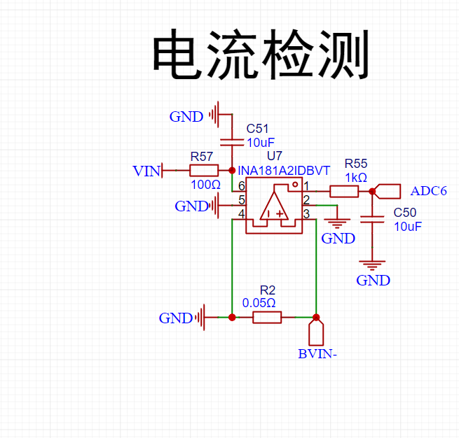
For other functions, refer to the open-source schematic.
Current features include
standard mode,
burn-in protection,
time display,
temperature, humidity, air pressure, and
power status.
Hourly chime , sleep mode
setting, time display, temperature, humidity, air pressure, power status, hourly chime, deep sleep, sleep screen display settings, environmental information ( temperature, humidity , air pressure , light intensity, brightness ) , screen brightness settings, voltage level automatic adjustment, UI dynamic , UI static, extremely dark mode , TV static linkage, voltage brightness magnification , compass, level, time settings ( seconds , minutes , hours, Sunday , month, year ) , alarm clock settings (10 alarms) , seconds, minutes, hours, Sunday , Saturday, Sunday, Sunday, Sunday, alarm clock duration switch, incremental alarm clock, stopwatch, sound settings (button sounds, sound length, master switch, tone adjustment, volume adjustment ) , flashlight , power management (external power supply, internal power supply , power supply voltage , charging current, remaining battery life protection (currently unavailable), system settings ( save parameters ) , anti-accidental touch (currently unavailable), 12-hour clock (currently unavailable ), screen flip (currently unavailable ), sleep schedule (currently unavailable), start sleep ( currently unavailable), end sleep (currently unavailable), system information (main controller model, thermometer, hygrometer , barometer, light intensity meter, accelerometer, magnetometer , clock chip, screen, main controller, number of buttons, version number, machine model , author, factory mode , sensor, temperature compensation , humidity compensation, air pressure compensation, ADC adjustment )


 京公网安备 11010802033920号

 IDT74FCT157TQB


