Video Link:
[Bilibili Video - Function Demonstration and Introduction] https://www.bilibili.com/video/BV1iSWVenErq/?vd_source=dcec384099758377125cc78a52ec1015
Project Introduction:
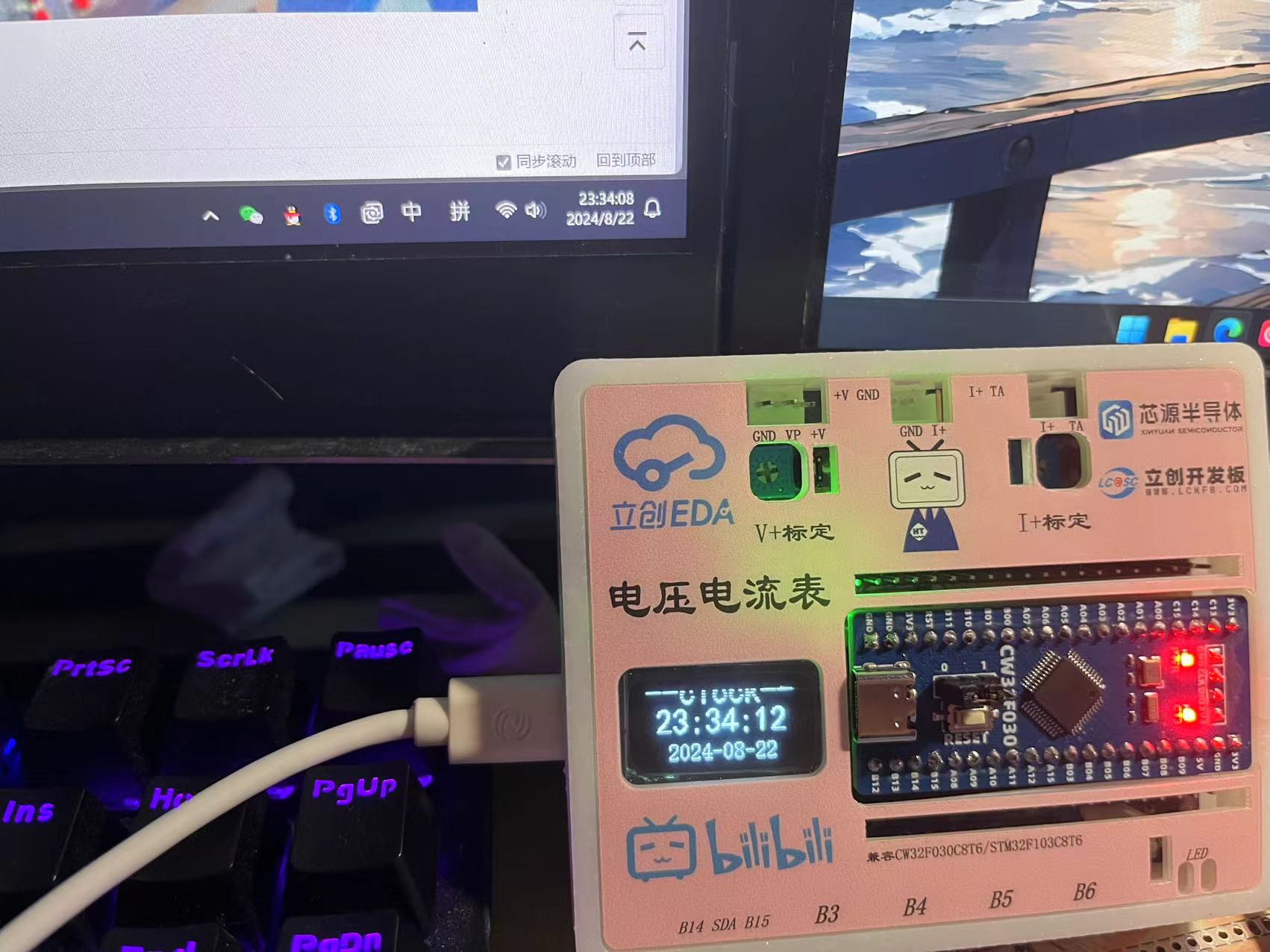
This project is a voltage and current meter developed based on the LCSC CW32 GeoStar development board. It can perform basic daily voltage and current measurements. The accuracy is similar; for precise measurements, please use a multimeter. This project is only for understanding the principles of voltage and current meters. In addition to the main functions, the board is designed with SPI... The OLED interface is used for displaying voltage and current values. It also features a CH340 serial port output for data transmission and reception. We use the MODBUS communication protocol. Originally, the design involved the host computer sending a request command for the voltage value. However, due to damage to the RX port of the LCSC development board, we adopted an active transmission method, with the output option set via a menu. The main reason for this was the lack of a virtual serial port function on the onboard Type-C, requiring an external USB-TTL connection, which is cumbersome. Additionally, the onboard ESP01S module interface can be used for IoT development, similar to MQTT. Here, we use it as a network clock to request network time data from an API. Due to time constraints, network weather functionality has not yet been implemented.
Project Functionality
: This design is a voltage and current meter based on the LCSC development board - LCSC:
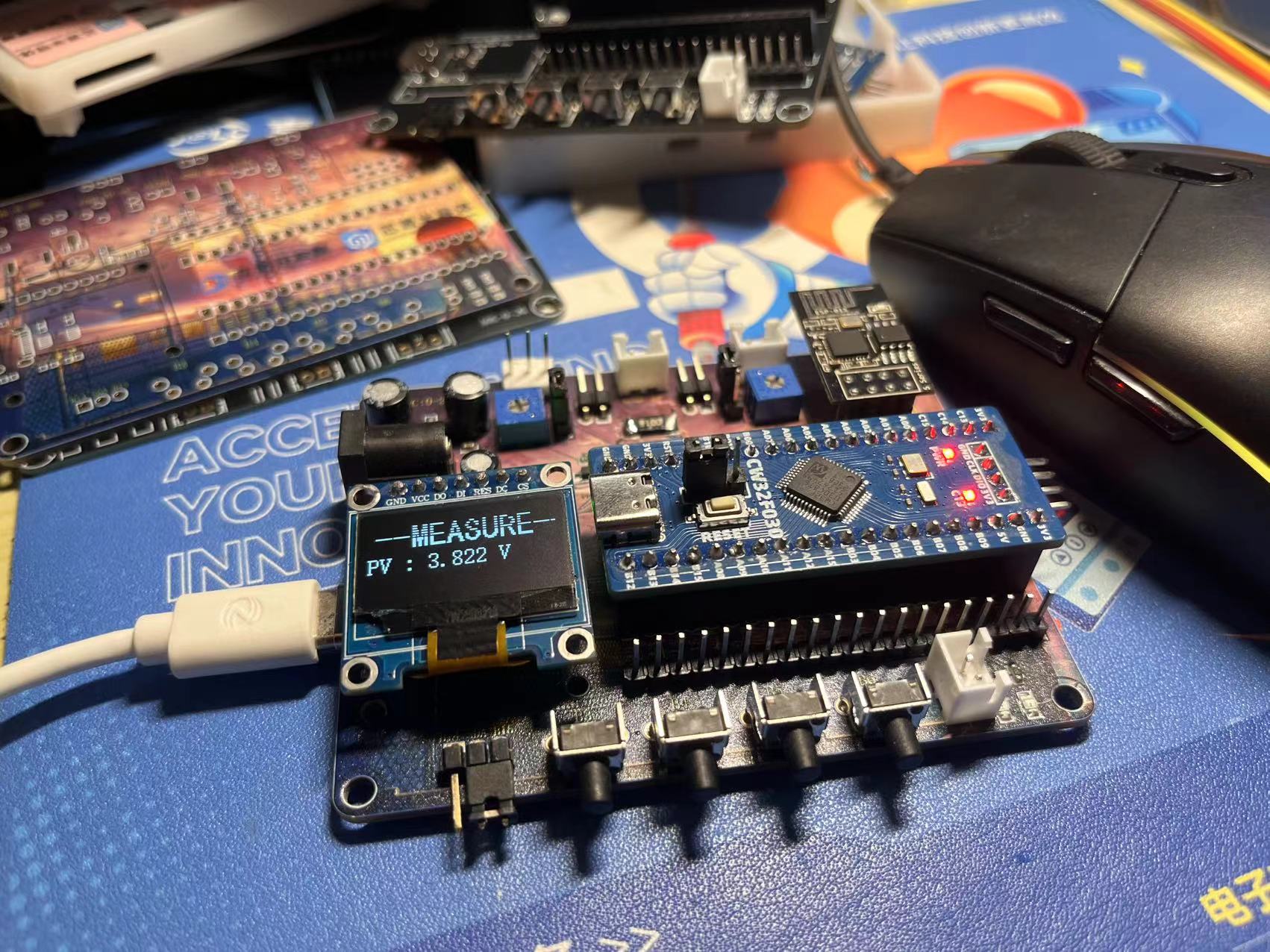
1. It has four buttons: Confirm, Previous, Next, and Return, used for menu operation and function settings.
2. The onboard Type-C-CH340 solves the problem of the LCSC requiring a USB-TTL module, enabling data transmission and reception. Here, it is used to upload voltage and current data to a PC host computer for observing voltage and current stability, trend changes, and repeatability accuracy.
3. Onboard 7-pin SPI OLED interface, also serving as a hardware IIC OLED, for SPI/IIC OLED learning.
4. Onboard ESP01S module interface, for wireless communication learning, IoT learning such as MQTT, network clock, weather clock, etc.
5. Onboard DC socket, input voltage is stepped down to 5V to power the system via a step-down chip.
6. Onboard voltage and current test terminal interface for voltage and current testing.
Materials Purchase:
1. LCSC development board: Diwenxing/Dikuoxing
2. ESP01-S WIFI module, recommended to purchase with the socket for easy serial port debugging
3. 0.96-inch SPI OLED
4. Buttons: Purchase side-mounted ones that extend beyond the casing.
Project Parameters:
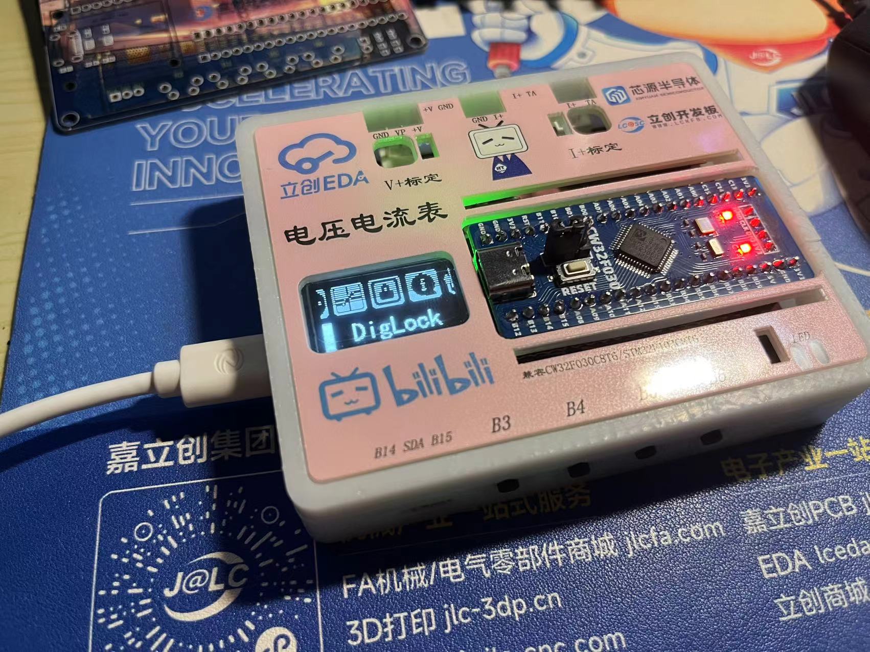
1. This design uses a 0.96-inch 7-pin SPI... 1. OLED for voltage and current display, menu display, and clock display
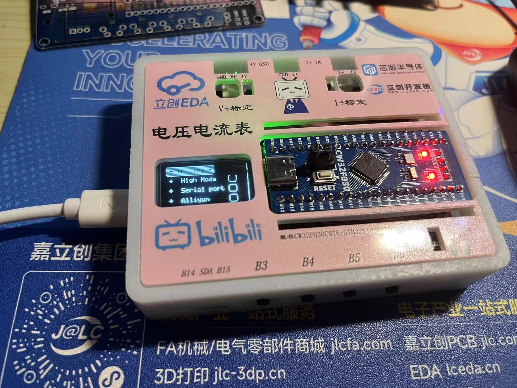
. 2. This design uses the ESP01-S module for network clock acquisition, and can also connect to Alibaba Cloud for data upload and command issuance, enabling IoT development.
3. This design uses the CH340 chip to solve the problem of the lack of a virtual serial port on the satellite.
Principle Analysis (Hardware Description)
: Here you can fill in the design principle of the project, breaking down and analyzing the design principle. Example:
This project consists of the following parts: power supply section, voltage sampling and calibration section, current sampling and calibration section, OLED section, ESP01S module section, USB-Type C section, button section, and LED expansion section. The expansion pin section of this project mainly uses two voltage acquisition circuits to divide different voltages to ensure that the voltage sampled by the input ADC is within a safe voltage range, with a maximum measurable voltage of 30V. The voltage measurement range can be expanded by changing different voltage divider resistors and internal reference voltages. The acquired voltage is output via serial port using the MODBUS communication protocol, which is more suitable for industrial environments. The OLED displays the corresponding voltage and current values. When not using a voltmeter or ammeter, the ESP01-S module is used to connect to the network and request network time. This board can be used as a small network clock, updating and calibrating every 5 minutes.
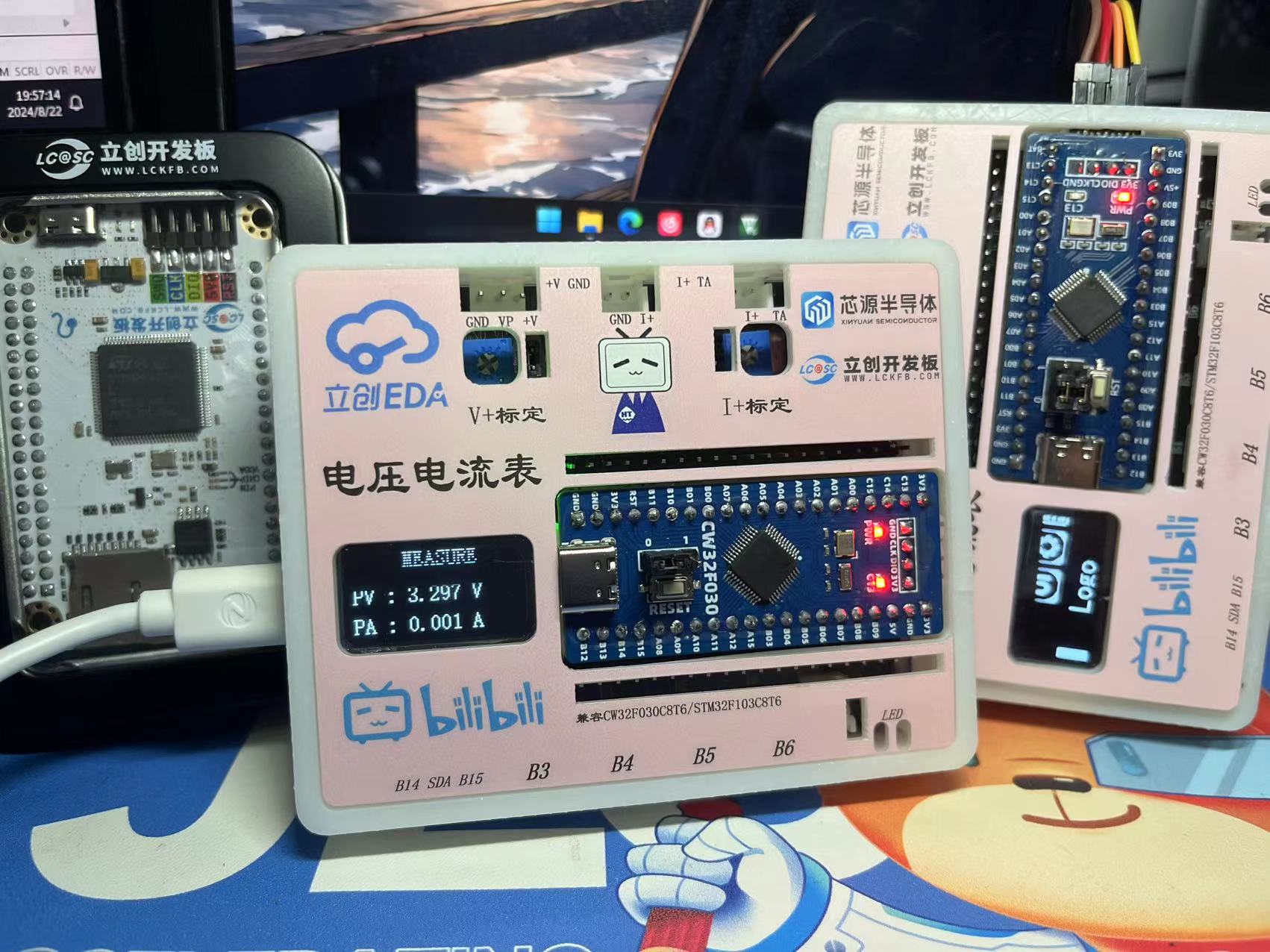

The display issue is related to the photo capture; the OLED is refreshed
. 1. Power supply circuit:
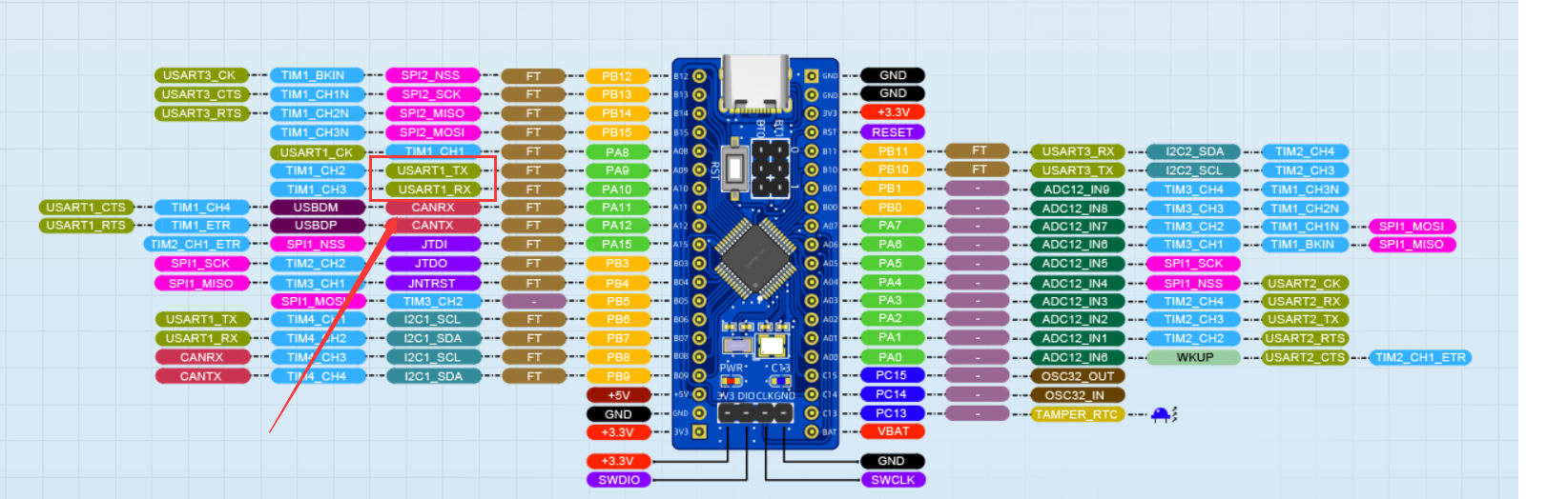
DC power can be used here, with an input range of 0-30V. The input voltage is reduced to 5V by the SE8550HF circuit. Alternatively, a TYPE-C-16P interface can be used as the power supply interface. The corresponding USB data pins are connected to the CH340 chip, and then to PA9 and PA10 for direct USB serial communication without the need for an external serial converter module. It should be noted that 5.1K pull-down resistors are added to the CC1 and CC2 pins to facilitate identification and configuration by different host devices. Also, since 5V power is used here, according to the datasheet, pin 3 of the CH340E should be connected to 100nF and then grounded.
Here are some details: PA9 and PA10 are used here for compatibility with STM32F103C8T6.


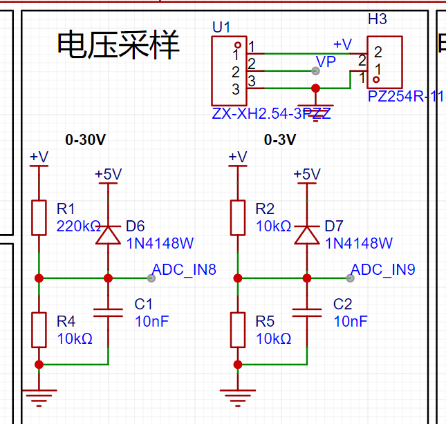
2. Voltage sampling and calibration:
The measured voltage is divided and input to ADC_IN8 and ADC_IN9 respectively. Shorting H7 allows the system voltage to be used as the measured voltage for testing. The input voltage can be adjusted by potentiometer R14. A diode 1N4148W is connected to protect the circuit.
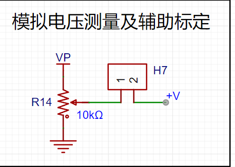
3. Current sampling and calibration:
The current sampling circuit inputs to ADC_IN7. Without connecting R6-100 milliohm resistor, H7 can be shorted to use voltage to simulate current.


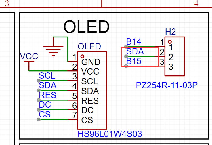
4. OLED section
: The pins here use SPI. A detail here is that the SDA pin can be shorted by PB14 or PB15, mainly for hardware IIC when using IIC OLED.

5. ESP01S module section
: The TX and RX pins of the ESP01S module are connected to PA2 and PA3.

6. Button section: The
button section is relatively simple and does not have pull-up pins. Note that the GPIO needs to be configured as a pull-up input.

7. LED expansion section
: The LED expansion circuit can connect to any other I/O.

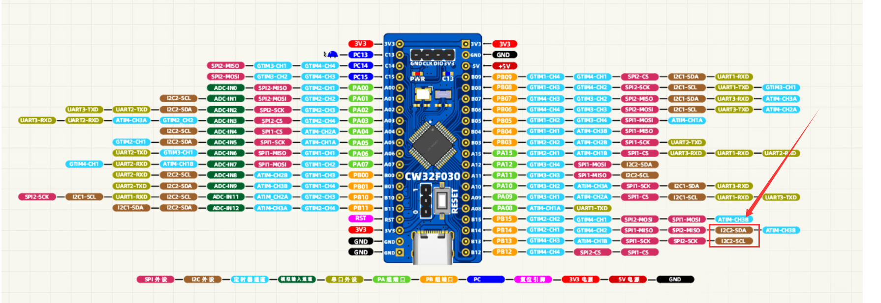
8. Extended pin section
: Bring out all pins for easy use and debugging.
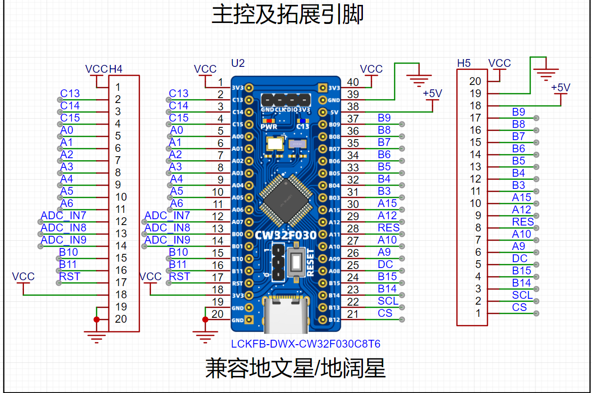
9. Schematic circuit design:
Here we can see that when I designed the schematic, I intentionally compared the Diwenxing and Dikuoxing boards, so that this board can be used as a development board in addition to completing the design of voltage and current meters. I also checked and the board is compatible with GD32E230C8T6. I haven't looked at other boards yet. When designing, I only combined the Diwenxing and Dikuoxing
software code
programs. For details, please refer to the attachment.
1. ADC sampling section
(1) Collect 4 channels, including the internal reference voltage AI17
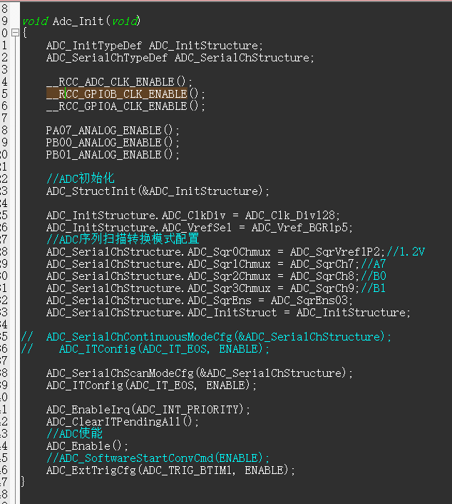
(2) The ADC adopts the external trigger mode, and the timer triggers sampling once every 1ms.

(3) Each time it is sampled, the data is pushed into the array. After the data is reached, the array value is averaged and then converted into the corresponding voltage and current value.

(4) In terms of output, when the 3V channel sampling is less than 4095, the 3V channel value is output as the sampling voltage. If it exceeds 4095, it will be converted to the 30V voltage divider channel output.

2. Menu porting:
Add response header file and initialize the function in the lower box.
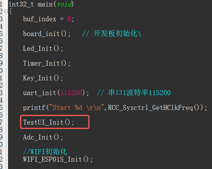
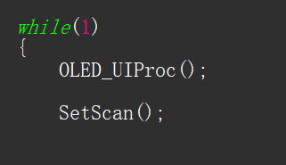
3. Add the function OLED_UIProc() to the main program;
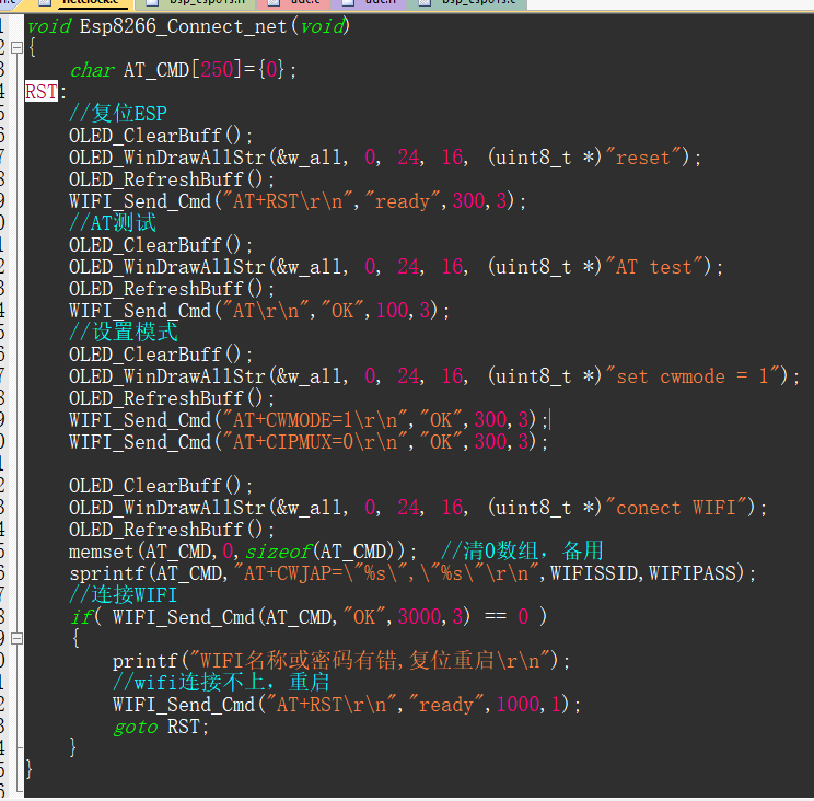
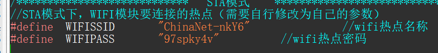
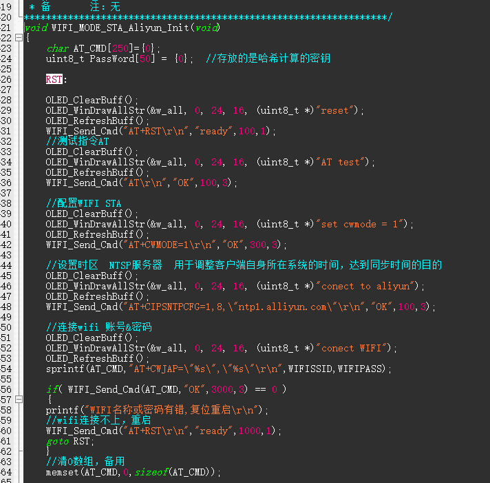
4. This function automatically connects to WIFI upon power-up. The WIFI name and password in the header file need to be modified.
5. The button part needs to be initialized as pull-up input. An external trigger is used here, detecting button presses in the interrupt and placing the key value into a queue.

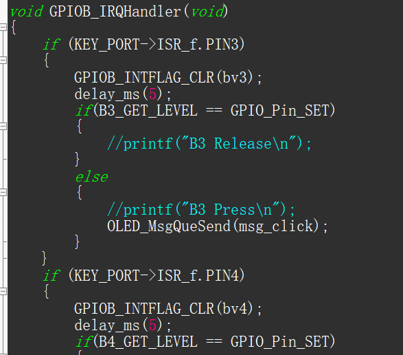
6. In the main loop, check the following flags and set them accordingly.

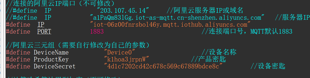
7. Connect to Alibaba Cloud. Here, data can be uploaded to the Alibaba Cloud server, or commands can be sent from Alibaba Cloud for control. Here, commands are sent to turn on the LED
. The triplet needs to be modified. Related tutorials can be found on CSDN.

Note
: When connecting the OLED, the SDA-PB15 pin of H2 needs to be shorted; otherwise, it will not light up.
Soldering:
It is recommended to solder CH340E first, then solder the C-pin. Use solder paste sparingly to avoid solder bridging. If possible, use a hot air gun with a low airflow. The
assembly process
involves first inserting the buttons, then

snapping on the cover
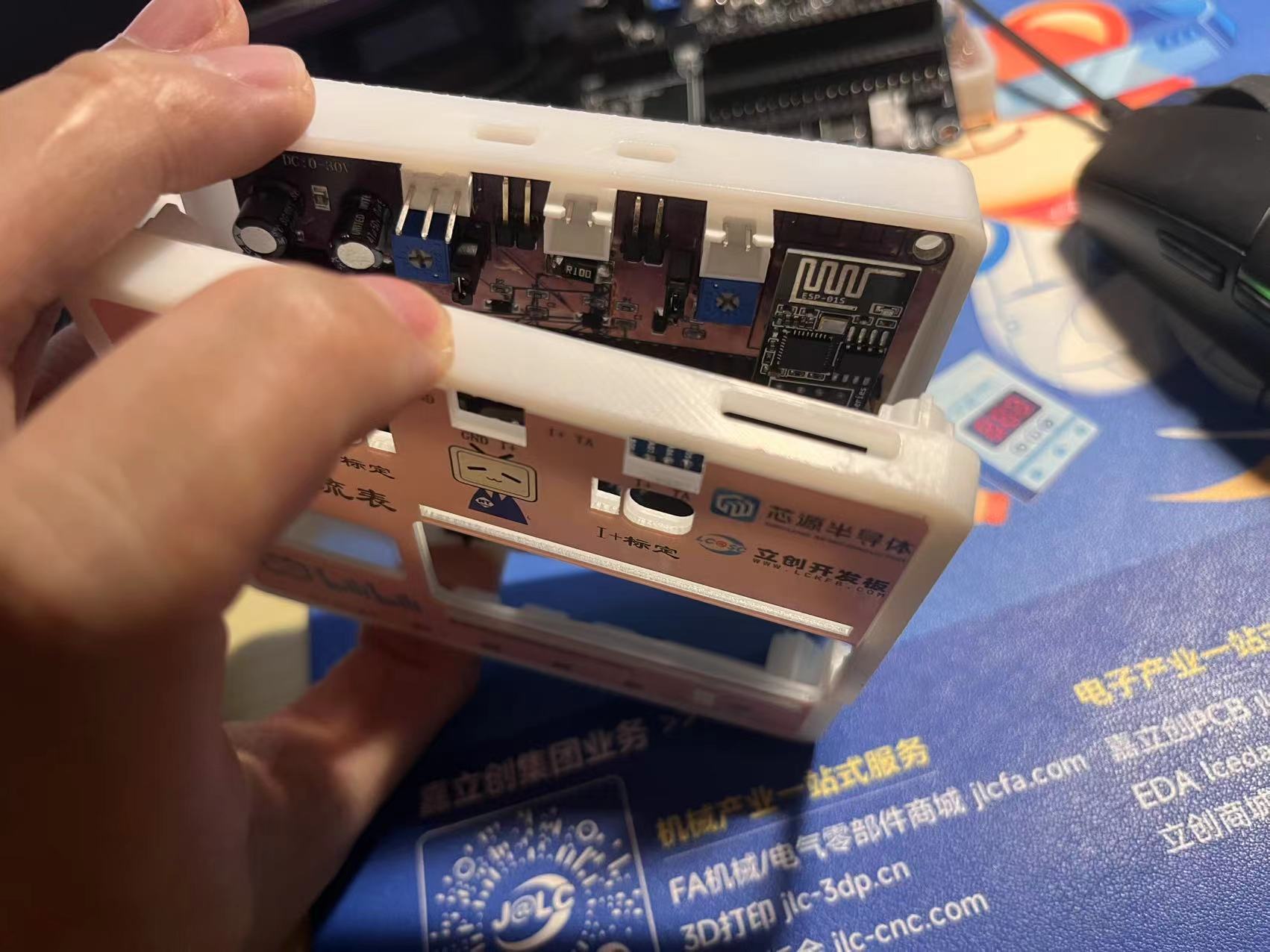
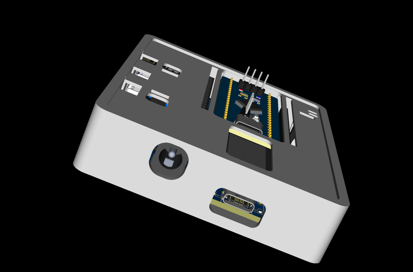
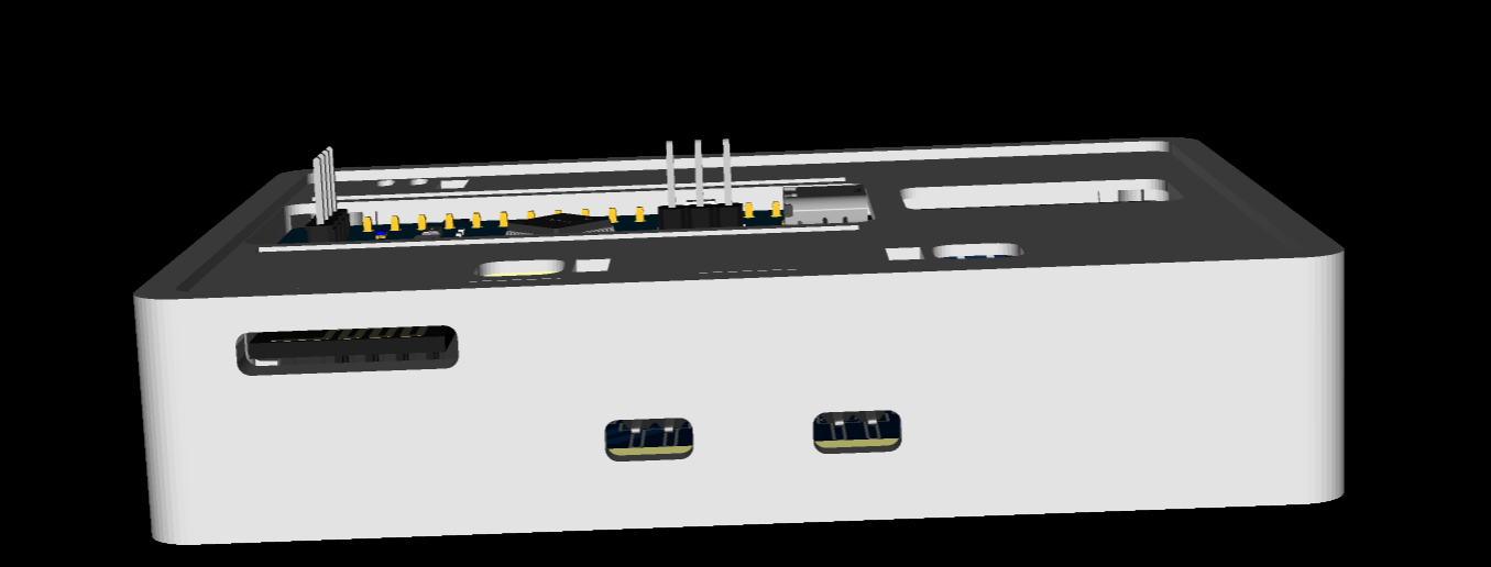
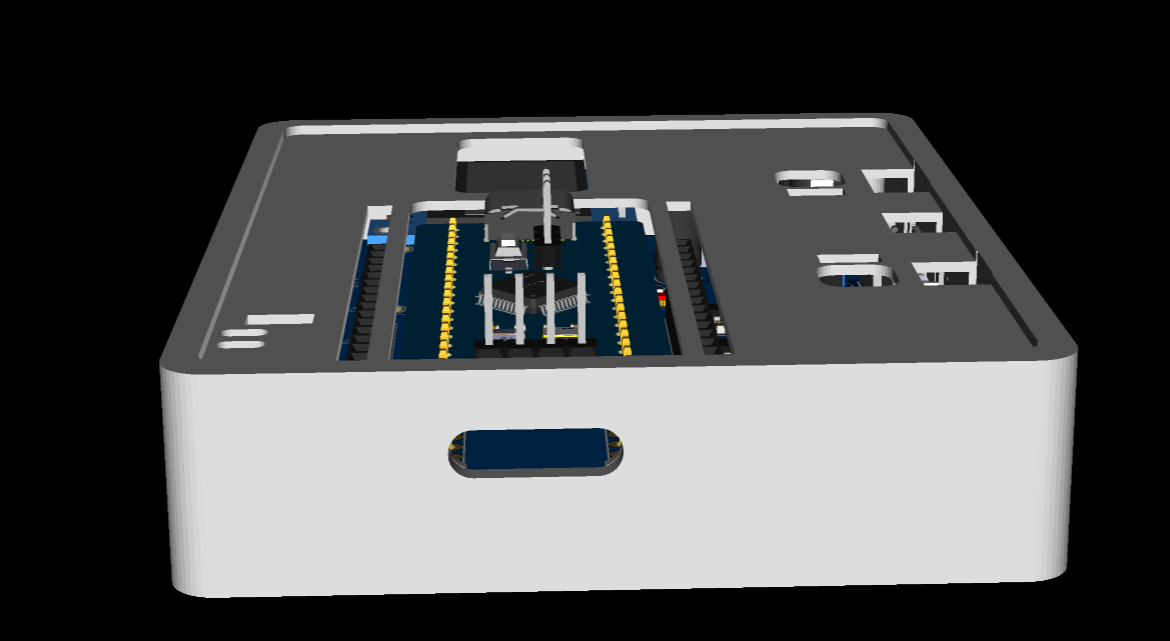
and screwing it in. The casing design is quite sophisticated; pillars are used to secure
it. ( Images
of the PCB and menu interface are

included .) The casing design features : 1. Side-mounted buttons for easier access ; 2. Power and communication ports ; 3. Rear panel with wireless module antenna output and voltage/current interface terminals; 4. Right-side output for download port wiring; 5. 1.6mm spacing between screw pillars, which is ideal for a 1.6mm board. The panel uses a custom-developed host computer that uses the MODBUS protocol to monitor current trends and adjustments, assess stability, and test repeatability. Attachments include: power supply measurement values compared with a multimeter ; J-Link power supply comparison program source code, etc.


 京公网安备 11010802033920号

 MSMA101


