Simple Digital Oscilloscope
1. System Power Supply
This project requires four voltage values: +5V, +3.3V, +12V, and -12V. The power supply uses a Type-C data line as the input and a boost converter chip MT3608 (input voltage 2V~24V, output current up to 2A) to convert the input voltage to +15V and -15V. +15V is obtained by passing through a 78L12 to get +12V, +15V is obtained by passing through a 78L05 to get +5V, and -15V is obtained by passing through a 79L12 to get -12V. As for +3.3V, it is obtained by using the classic AMS1117. (VBUS is +5V)
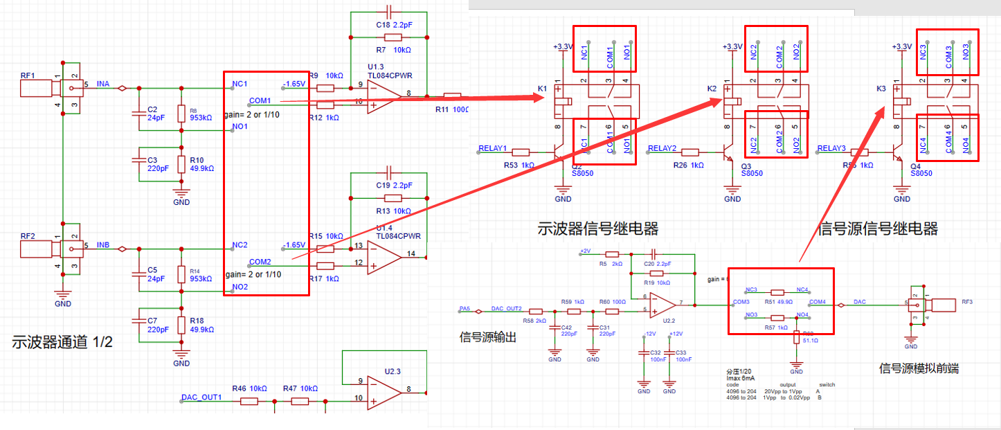
2. The analog input channel
expansion board provides two oscilloscope input channels, as shown in the figure below. It includes signal conditioning implemented by resistor voltage divider and operational amplifier, and square wave output implemented by comparator (for triggering and frequency measurement).
INA and INB are the two input terminals of the oscilloscope. The analog input signal is connected to the positive pin of the SMA straight connector here. The input impedance of 1MΩ is achieved by series voltage divider through resistors (953K and 49.9K) and two signals are generated for selection: one input is direct and the other is attenuated to 1/20.
The operational amplifier uses a TL084 (integrated quad op-amp), powered by dual +12V and -12V power supplies;
AnalogA and AnalogB: Analog signals amplified and shifted by the inverting amplifier are connected to the STM32H750 development board and sampled by the H750's ADC;
TrigerA and TrigerB: Square wave signals generated by AnalogA, AnalogB, and a DC reference level (generated by one of the H750's DACs) after passing through a comparator, are input to the STM32H750's timer for frequency measurement;
DAC_OUT1: DC reference level, output through the STM32H750's internal DAC configuration.

First, we know that when the VREF of the STM32H750 is powered by 3.3V, the input range of the STM32's ADC is 0-3.3V. However, our input signal has a maximum range of ±15V. Therefore, we need to solve the problem of large signal input not being saturated. Let's solve an equation:
15 * a + b = 3.3;
-15 * a + b = 0;
We can get a=0.11, b=1.65;
That is to say, we need to attenuate the input signal to at least 0.11 times (approximately 1/9) and add 1.65V DC to meet the full-scale input of the ADC sampling.

According to the superposition theorem, we first analyze the contribution of the input signal AIN to the output Vo. By grounding the other voltage source in the circuit, -1.65V, the input signal is divided to 1/20 after passing through R8 (953K) and R10 (49.9K), and then amplified by a factor of 2 by the non-inverting amplifier circuit. The overall gain of the input signal is 1/10. When analyzing the contribution of DC -1.65V to the output Vo, with the input signal AIN grounded, the amplification factor of -1.65V is -1. Therefore, the output Vo = -1.65V * (-1) + AIN/10 = 1.65V + AIN/10.
The -1.65V voltage is generated by the following circuit;

having solved the problem of matching the ±15V input to the 0-3.3V input range of the ADC, we also need to consider the problem of accurate sampling even when the input signal is small. For example, when a 10mV signal is input, it will attenuate to 1mV after passing through the above circuit. To ensure the signal-to-noise ratio of the input signal as much as possible, we add a switching mode to the analog front end. When sampling a small signal, we use a switch to select the direct INA signal to the non-inverting input of the op-amp, instead of selecting the signal attenuated by INA to enter the non-inverting input of the op-amp. This ensures that the signal entering the ADC is as large as possible. Combined with a 16-bit ADC, the sampling results can be accurate and reliable.
3. The analog output channel
expansion board provides one signal output channel, as shown in the figure below, including resistor voltage divider and signal conditioning implemented by operational amplifier;
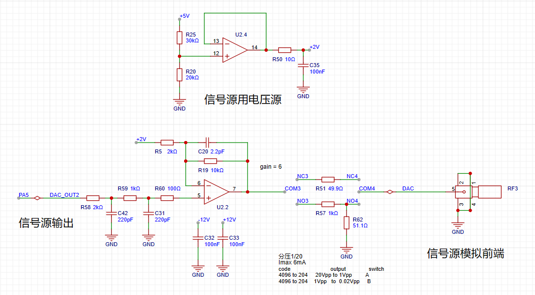
we know that when the VREF of the STM32H750 is powered by 3.3V, the output range of the internal DAC is 0-3.3V. To achieve ±10V output, we need to solve the equations:
0*a + b = -10V;
3.3*a + b = 10V;
Solving for a=6.06, b=-10;
In the diagram above, the 0-3.3V signal output from the DAC (PA5) inside the STM32H750 is passed through a two-stage RC low-pass filter and then input to the non-inverting input of the TL084, forming a non-inverting amplifier with a gain of 6. After amplification, the waveform is 0-19.8V; Then, using the -5x amplification capability of the inverting amplifier section of the TL084, the +2V obtained by voltage division of 5V is amplified by -5x to obtain -10V, which is superimposed with the 0-19.8V signal output from the non-inverting amplifier to obtain an output of approximately ±10V. The calculation formula is: Vout = -10 + 6*Vin.
4. Comparator Circuit
The comparator uses an LM393 (dual-channel), powered by +5V; In order to realize the trigger function and frequency counter function, we designed two comparator channels on the board to convert the waveforms of the two analog input channels before entering the ADC into square wave signals for use as timer inputs of the H750. The reason for using the waveform before entering the ADC for comparison is that the waveform entering the ADC has been conditioned by the front-end analog circuit and falls within the known 0-3.3V range, making the comparator's comparison threshold easier to design.

As shown in the diagram above, the H750 uses its internal DAC to output a 0-3.3V DC signal to compare with the waveform of channel 2 before entering the ADC, converting the channel 2 waveform into a square wave. This allows the H750's timer function to use the square wave signal for interrupt handling and timer capture.
5. Channel selection
uses a relay as a selection switch to select either a direct signal or a signal attenuated to 1/20th of its input to the first-stage non-inverting amplifier. The non-inverting amplifier performs two tasks: first, it amplifies the input signal at the non-inverting input by a factor of two; second, it shifts the amplified signal by 1.65V, calculated as Vo = 1.65 + 2*Vi.
A signal switch (relay or manual switch) is added after the 1M ohm input voltage divider resistor to select whether the AIN signal enters the op-amp's non-inverting input directly or after being divided to 1/20th of its input. For both methods, the input impedance for the AIN signal is 1M ohms. When we need to acquire small signals, we can toggle the switch to use the direct input to obtain more accurate measurement results. We can calculate that when the direct input is selected, Vo = 2*AIN + 1.65, while when the attenuation input is selected, Vo = AIN/10 + 1.65. Therefore, the overall gain of the corresponding circuit is 2 times or 1/10 times.
The signal source relay uses a voltage divider network to achieve good results when outputting small signals using analog circuit voltage division. Similar to an ADC, the DAC's resolution is a problem in order to cover the signal source output from ±10mV to ±10V while balancing a large signal range and small signal accuracy. The H750's DAC is 12-bit, and its full-scale output (when all 4096 code values are used) is ±10V. When we reduce the DAC code value to output a small signal, to achieve a waveform voltage resolution of 7 bits (i.e., a vertical resolution of 128 points), the waveform must be attenuated by 128/4096 = 1/32. Converted to an output voltage range of ±10V/32 = ±0.3215V, for signals smaller than ±0.3125V, further reducing the code value will result in insufficient DAC resolution and noticeable waveform step-offs. Therefore, we used an analog voltage divider approach. When outputting signals smaller than ±0.3125V, we used a switching resistor divider to attenuate the waveform by 1/20, ensuring voltage resolution for small signals. Simultaneously, the combination of R57 and R62 ensures the output resistance is 50Ω at 1/20 attenuation, and R51 ensures the output resistance is 50Ω at x1. This is used
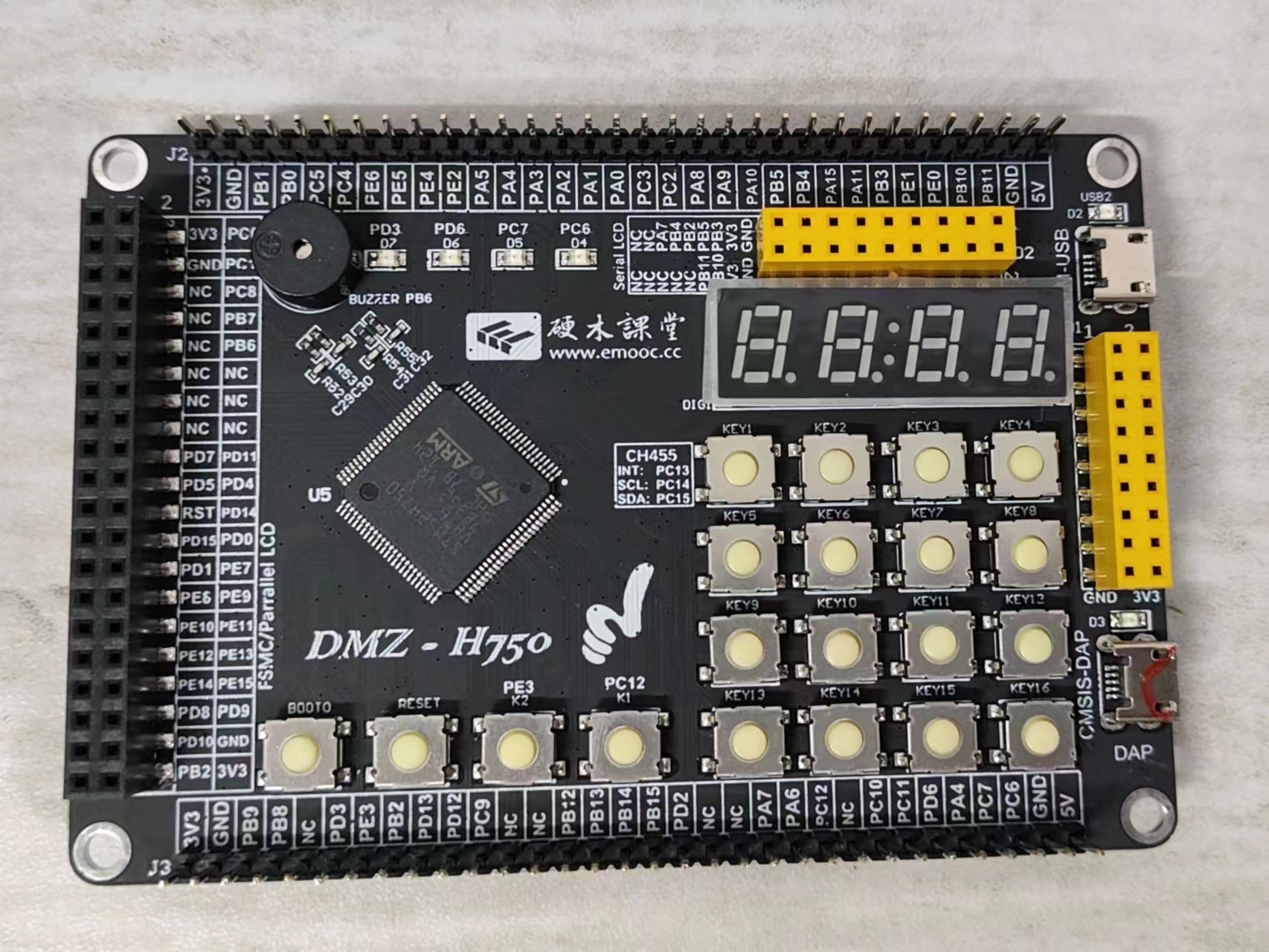
with the Hardwood Classroom H750 core board, as shown in the diagram below:
PDF_DigitalOscilloscope.zip
Altium Digital Oscilloscope.zip
PADS_DigitalOscilloscope.zip
BOM_DigitalOscilloscope.xlsx
97062
[Color Silkscreen Printing] Genshin Impact Transformation Device [Voice Playback]
Genshin Impact Transformation Driver
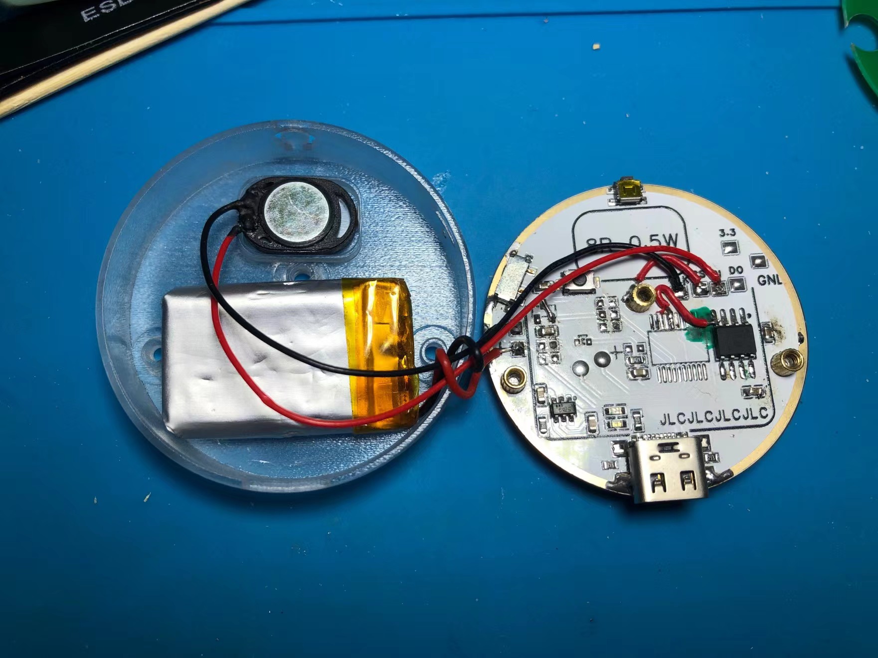
The Genshin Impact transformation device
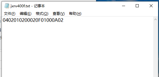
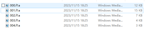
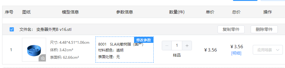
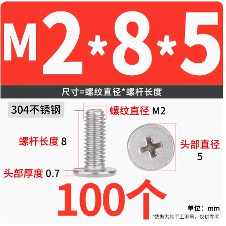
is now complete . The design is inspired by the Kamen Rider transformation device and incorporates its features. The pattern is from the official badge stickers released by miHoYo; other patterns can be used as needed. It uses the reprogrammable chip WT588D-20SS, which is readily available and easy to use (but has been discontinued due to its age and inability to be driven after downloading). A nine-core NV400F chip has been replaced. Single-piece and four-piece prototypes were created within the project. The four-piece prototype requires manual cutting but is more cost-effective. Printing is optional. The board features a pure bottom-layer layout with no vias. To ensure a complete top surface soldering, the positioning posts for the Type-C port, switch, and buttons need to be cut off. The images below are from the old version; the new PCB has been redrawn. Operation: Pressing the top button produces a sound effect. The board is only designed for single-button operation, but multi-button operation and programming are possible; modifications can be made if needed. The burning tutorial and software file are too large to upload. They have been uploaded to Baidu Cloud via this link: https://pan.baidu.com/s/17g81MBAu6D0OjQcWWzcYtQ?pwd=td40 Extraction code: td40. The official TTL burning tutorial verification failed; an offline dongle is used for burning. The dongle needs to be purchased separately. [Offline Dongle Copying] The audio conversion software in the package converts MP3 audio to FLA format. Import all audio files and command txt files into the offline dongle. The key command is "down". The format must start from 000, otherwise it will not be recognized . Due to space limitations on the PCB , various coil types were tested. A single coil can be recognized, but after adding a battery, the coil cannot be recognized because the battery shields the operation. Neither of the two PCBs in the project could be used, so a self-made coil was finally used. The phone can recognize the device after adding a battery in the project. The outer shell is made of 3D transparent 8001 stainless steel. The version shown in the project is without chamfering and logo. The STL file in the link has been refined; you can choose to print it yourself. Fasteners: 3 M2 screws , 6 M2 knurled nuts (just align them). Battery: C5182591 , size 402030. You can purchase this yourself. For the project, you can choose a smaller battery from LCSC. Speaker: C530539 GSPK151035PN-8R0.5W-L35-1.25T chip, can directly drive an 8R0.5W speaker. You can purchase this yourself. Other power ratings like 1W and 0.7W can also be driven. Video: https://www.bilibili.com/video/BV18N411u7Hr/?spm_id_from=333.999.0.0


3DShell_3DShell_the board is here, this is the one_B v6.stl
fb866a4dfd2578ca98d06a58ca9576bb.mp4
PDF_【Color Silkscreen】Genshin Impact Transformation Tool【Voice Playback】.zip
Altium_【Color Silkscreen】Genshin Impact Transformation Tool【Voice Playback】.zip
PADS_【Color Silkscreen】Genshin Impact Transformation Tool【Voice Playback】.zip
BOM_【Color Silkscreen】Genshin Impact Transformation Tool【Voice Playback】.xlsx
97063
electronic


 京公网安备 11010802033920号

 8D015W05SC


