I. Project Background and Significance:
With the development of technology, intelligent vehicles have been widely used in various fields, such as industrial automation, home services, and healthcare. Among them, the line-following vehicle, as a type of intelligent vehicle, can travel along a preset trajectory and has high practical value. This project aims to design and implement an automatically line-following vehicle using a Liangshanpai microcontroller to promote the popularization and application of intelligent vehicles.
II. Project Objectives:
Design and implement an automatically line-following vehicle with high stability and reliability. The vehicle should be able to travel automatically according to a preset trajectory and adapt to different terrains and environments. The vehicle should possess certain intelligence, such as automatic obstacle avoidance and automatic speed adjustment. Mobile remote control function: Users can remotely control the vehicle's movement via a mobile app, including starting, stopping, speed adjustment, and trajectory setting.
III. Technical Approach:
The Liangshanpai microcontroller is used as the control core of the vehicle, responsible for processing signals from various sensors and controlling the vehicle's movement.
The Liangshanpai microcontroller features high performance, low power consumption, and low cost, making it very suitable for controlling intelligent vehicles. Infrared sensors are used as tracking sensors to detect the trajectory in front of the car.
Infrared sensors have advantages such as high sensitivity and fast response speed, enabling accurate detection of the trajectory. A PID algorithm is used to implement tracking control of the car, allowing it to stably travel along the preset trajectory.
The PID algorithm is a classic control algorithm that can effectively adjust system deviations to achieve a stable state.
Remote control function: Remote communication between a mobile app and the car is achieved via Bluetooth or WiFi.
Users can remotely control the car's movement through the app, including starting, stopping, speed adjustment, and trajectory setting.
IV. Project Implementation Steps:
Hardware Design: Design and manufacture the car's hardware components, including motor drive circuits, sensor interface circuits, and wireless communication modules. During hardware design, factors such as stability, reliability, and power consumption must be fully considered.
Software Design: Write the car's control program, including tracking algorithms, obstacle avoidance algorithms, automatic speed adjustment algorithms, and mobile remote control functionality. During software design, factors such as program efficiency, stability, and readability must be fully considered.
System Integration: Integrate the hardware and software together and conduct system testing. During system integration, it is essential to ensure compatibility, stability, and reliability among the various components.
System optimization: Based on test results, the system will be optimized to improve the car's performance. During system optimization, the actual application environment and user needs of the car must be fully considered.
V. Expected Outcomes:
A car capable of automatic line following will be completed, possessing stability, reliability, and intelligence. This car will be able to travel stably on a preset track and adapt to different terrains and environments. Furthermore, the car will possess certain intelligent features, such as automatic obstacle avoidance and automatic speed adjustment. The mobile phone remote control function allows users to control the car more conveniently, enhancing its practicality and fun. The successful development of this car will provide new ideas and solutions for the popularization and application of intelligent cars.
VI. Circuit Design and PCB Design: The

infrared tracking module is a crucial part of the line-following car. It is responsible for detecting black lines on the ground and sending the detected signals to the microcontroller for processing. Below is a simple analysis of the infrared tracking module circuit.
Infrared Emitter and Receiver: The infrared emitter and receiver are the core components of the infrared tracking module. The transmitting tube emits infrared light, and the receiving tube receives the reflected infrared light. When the transmitting and receiving tubes are aligned with the black line on the ground, the receiving tube receives the reflected infrared light, generating a high-level signal.
Amplification circuit: Because the signal generated by the infrared receiving tube is relatively weak, it needs to be amplified by an amplification circuit before it can be recognized by a microcontroller or other devices.
Filtering circuit: The amplified signal may contain some noise; the filtering circuit can remove this noise and improve the signal purity.
Schmitt trigger: A Schmitt trigger is a shaping circuit that converts the input signal into a rectangular wave, facilitating digital processing by a microcontroller or other devices.
Logic circuit: The logic circuit can determine whether the car is on the black line based on the signal output by the Schmitt trigger. When the car is on the black line, the logic circuit outputs a high level; otherwise, it outputs a low level.
Power supply circuit: The infrared tracking module requires a DC power supply. The power supply circuit converts the battery voltage to a voltage suitable for the operation of the infrared transmitting and receiving tubes.
Through the above circuitry, the infrared tracking module can detect the black line on the ground and send the detected signal to the microcontroller for processing. The microcontroller can control the car's direction of travel based on the received signals, achieving a line-following function.
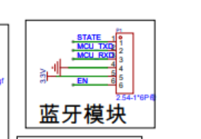
The Bluetooth module used is the HC-04D dual-mode SPP2.1 + BLE4.0 wireless serial communication module with a baseboard and solder pads; it can be easily found on Taobao.
It supports both SPP2.1 and BLE4.0 protocols. It integrates Bluetooth RF, baseband, protocol stack, and application layer, enabling wireless serial communication.
SPP2.1 is the Bluetooth serial protocol, allowing data transmission between Bluetooth devices via serial port. This protocol is simple, reliable, and widely used for communication between various Bluetooth devices.
BLE4.0 is the low-power version of Bluetooth 4.0, featuring lower power consumption, longer transmission distance, and faster transmission speed. BLE4.0 is ideal for applications requiring long standby times and low power consumption, such as smart homes and wearable devices.
The HC-04D Bluetooth module can communicate with microcontrollers, microcontrollers, and other devices via serial port to achieve wireless data transmission. Its applications are very wide-ranging, including smart homes, industrial control, medical equipment, and smart wearable devices.
In summary, the HC-04D Bluetooth module is a powerful and widely applicable wireless communication module. It can be used for both classic Bluetooth data transmission and Bluetooth Low Energy applications, providing developers with more options.
More importantly, it is inexpensive, making it suitable for this application.

In the use of edge-mounted LED lights, a resistor is usually connected in series. The main functions of this resistor are as follows:
Current limiting protection: LEDs are semiconductor devices, and the magnitude of their operating current greatly affects their lifespan and operational stability. If the operating current is too high, the LED may overheat, leading to a shortened lifespan or even burnout. Connecting a resistor in series limits the LED's operating current, ensuring normal operation.
Brightness adjustment: The brightness of the LED can be adjusted by changing the resistance value of the series resistor. In practical applications, the resistance value can be adjusted as needed to achieve the desired brightness effect.
Flicker prevention: In some cases, LEDs may flicker due to power supply voltage fluctuations or other reasons. Connecting a resistor in series stabilizes the LED's operating voltage, reducing flickering.
Voltage matching: There may be a difference between the LED's voltage and the power supply voltage. Connecting a resistor in series helps match the voltage, ensuring the LED's normal operation.
When choosing a resistor value, the rated current and voltage of the LED light are usually considered. Generally, 10kΩ or 100Ω resistors are common choices because they provide sufficient current limiting without significantly affecting the brightness of the LED light. Of course, the specific resistor value needs to be selected based on the actual situation.

The battery uses two 18650 batteries, providing a combined 7.4V. A charger is also included with the purchase, making it a great value.


 京公网安备 11010802033920号

 K12GO15N


