Verified. Firmware source code and shell drawings are attached.
⚠️ Automatic wiring warning (works but not aesthetically pleasing).
Design references (thank you very much!): Lemon, felix-m
⌨️ 2024 Keyboard List:
DecaDeca - 43-key dual-mode keyboard;
DecaDeca Split - 45-key Bluetooth split keyboard;
4x10 Bluetooth split keyboard;
4x12 Bluetooth split keyboard
; 4x12 Bluetooth keyboard (compatible with JJ40 aluminum shell);
44-key orthogonal keyboard (with knob)
; 4x3 to 4x16 freely combinable keyboard;
4x3 to 4x16 freely combinable keyboard (thin version)
. ---
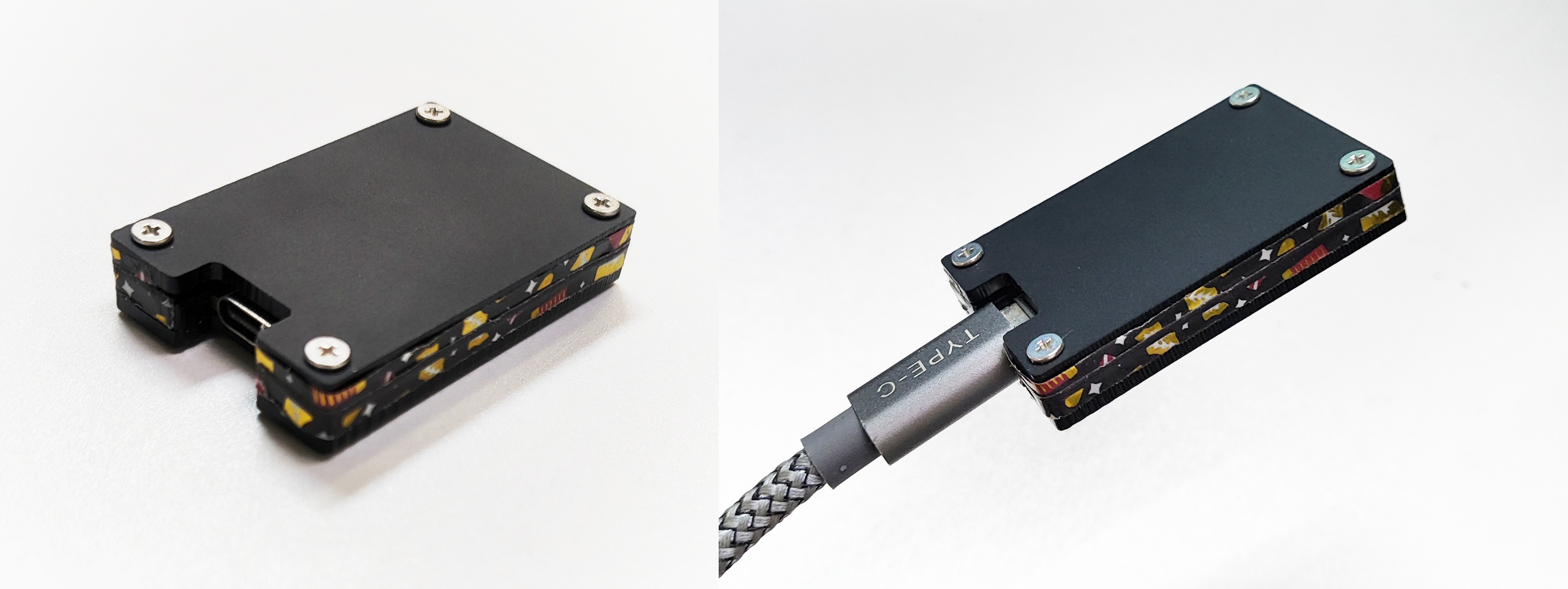
The shell is made of stacked acrylic, and the thickness after assembly is approximately 1.1cm. The PCB side will be exposed; you can use washi tape to cover the bleed lines.
The PCB is compatible with lithium batteries and CR2032 button batteries, but currently only a button battery version of the shell has been made.

---
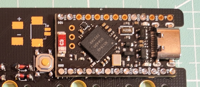
Main Control Board: The
main control board is ProMicro NRF52840, also known as SuperMini NRF52840, which can replace Pro Micro, Nice!Nano, nRFMicro, etc.
Related materials: I, II.
The main control board is directly soldered onto the PCB to reduce thickness (the holes in the upper half, except for the leftmost one and the two GND holes, can be left unsoldered):
---
The PCB
is the same for both sides. Compatible with 2U space.
If using a lithium battery, the power switch must be turned on during charging.
Soldering order: Diodes and hubs in the first row -> Reset button, power switch -> Battery holder (optional) -> Main control board -> Remaining diodes and hubs


-
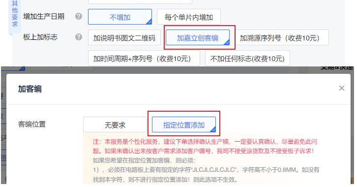
The "JLCJLCJLCJLC" on the board is used to specify the customer-designed printing position during PCB fabrication (no need to confirm the production draft). It can be deleted if not fabricating with JLCPCB:

---
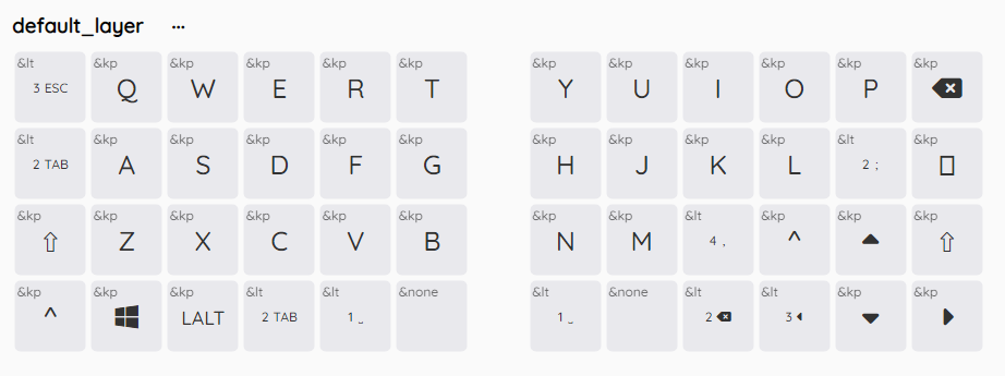
Firmware
uses ZMK firmware.
Bluetooth connection supports 5 devices by default. Switch devices via buttons. See the official documentation: Bluetooth, Bluetooth Behavior for details. Two firmware versions were created:
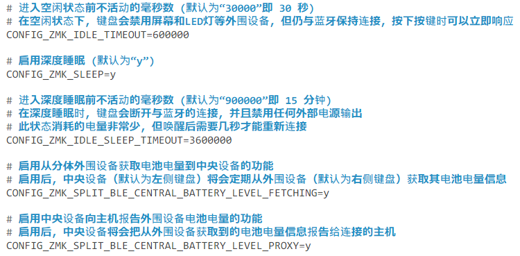
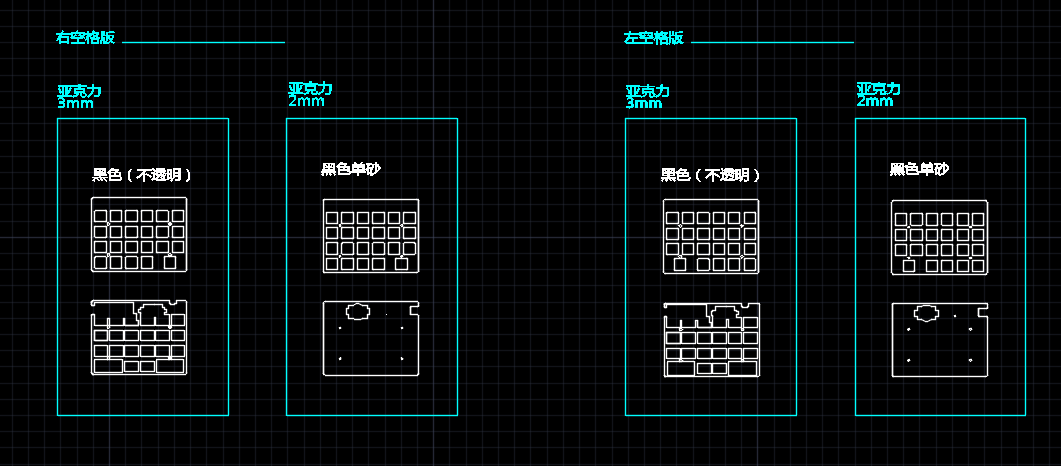
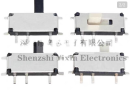
4x12_Split (Wired & Bluetooth Dual Mode): This uses a pair of keyboards as separate keyboards. The left keyboard is the central device, and the right keyboard is the peripheral device (the right keyboard sends signals to the left keyboard, which then sends them back to the host). The right keyboard can only be used when the left keyboard is switched on; the right keyboard does not support wired mode. By default, only the left keyboard's battery level is displayed (see the official documentation: Battery Level). You can enable the option to display the right keyboard's battery level in the configuration file (this firmware already has this option enabled) and check the right keyboard's battery level using battery display software (such as ZMK Split Battery). The right keyboard consumes less power than the left keyboard. The corresponding firmware needs to be flashed separately for each keyboard, and then each keyboard needs to be reset to pair. 4x12_Split_Dongle (2.4G & Bluetooth Dual Mode): Essentially a three-part keyboard: a ProMicro NRF52840 development board is used as the central device (i.e., receiver), and the left and right keyboards are used as peripheral devices. The receiver can be plugged into a computer via a data cable or an A-to-C adapter to use the keyboard on computers that do not support Bluetooth (similar to 2.4G). It can also be connected to a charger or battery case to use Bluetooth. The input voltage should be below 5V. A Google search for "zmk dongle" will find more information, such as: zmk-enki42-dongle, SliceMK Docs - Dongle vs Dongleless. A schematic of the receiver's acrylic casing is provided at the end of this document. Power consumption difference between the central and peripheral devices (via SliceMK Docs): Receiver (casing schematic attached): (The sample height was miscalculated, resulting in a gap, so it was sealed with washi tape). - Tutorials on compiling firmware online via GitHub can be found in the official documentation: Installing ZMK. Firmware writing tutorials can be found in the official documentation: New Keyboard Shield. Many keyboard firmware source codes are also available in the official repository for reference. You can set sleep time, battery display, and other items in the conf file: - ZMK Studio now supports real-time key remapping in wired and Bluetooth modes, but the software is still in beta, with very limited functionality, cumbersome operation, and bugs, so its use is not recommended. (October 2024) It is recommended to use Keymap Editor in conjunction with GitHub for online key remapping. Website information can be found at: Keymap Editor WIKI. Each key remapping requires recompiling and flashing the firmware. (The firmware provided here only has a basic letter layer and is for testing purposes only.) Clicking this option allows you to quickly modify key values using an existing keyboard (pressing a key on the keyboard will automatically fill the corresponding key in the selected cell): --- Keyboard Shell - Button Battery Version: (The drawings are for a single keyboard; if you want to make a split keyboard, you need to cut it into two parts.) 4 acrylic panels. Color annotations can be changed using CAD. There are three versions: left spacebar, right spacebar, and full 1U. The difference lies only in the top two panels (i.e., the positioning panels). Receiver Housing: --- Materials List Keyboard: Item No. Name Quantity Reference Diagram Remarks 1 Switch Number of Keys 2 Surface Mount Diode (1N4148 LL34 1206) Number of Keys 3 Kailh Hot-swappable Switch Number of Keys 4 ProMicro NRF52840 Development Board 2 5 MSK-12C02 Miniature Toggle Switch (Horizontal) 2 Handle Length 1.5mm 6 4*4 Tactile Switch 2


1.5mm height;
7.
Lithium battery;
2.
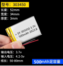
Thickness below 4mm (choose either lithium battery or button battery holder);
8.
CR2032 BS-6 button battery holder;
2.

(choose either lithium battery or button battery holder);
9.
Anti-collision particles
; 8.
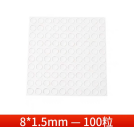
Used to elevate the keyboard and prevent slippage. Recommended height: 1.5mm and 8mm.
For the casing:
Item No.
Name
Length
Quantity
Remarks
1
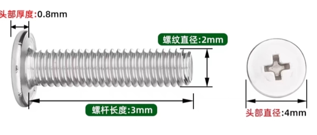
M2 flathead screw
6
4
Keyboard casing - top plate
2 M2 flathead
screw
4
4
Keyboard casing - bottom plate
3 M2 flathead screw 3 8 Receiver casing 4 M2 nut 6 4 Keyboard casing 5 M2 nut 3 4 Receiver casing screw/nut size reference (image from Taobao seller) --- Troubleshooting : Single key not triggered: Check for missing solder joints and proper soldering of the diode and switch seat. Check if the switch feet are inserted straight into the switch seat. Replace with another switch. Entire column/row of keys not triggered: Ensure the corresponding interface on the main control board is properly soldered to the PCB. Reset button not working: Ensure the RST and GND connectors on the main control board are properly soldered to the PCB. Power switch not working: Ensure the B+ and GND connectors on the main control board are properly soldered to the PCB. Check if the positive and negative terminals of the battery or battery holder are soldered in the correct positions. If using a coin cell battery, check if the battery is installed correctly. Bluetooth cannot connect: Clear the corresponding Bluetooth profile (see official documentation: Bluetooth, Bluetooth Behavior). Flash "settings_reset-nice_nano_v2-zmk.uf2" to reset the keyboard (see official documentation: Connection Issues). Coin cell battery installation method:

4x6-case 2024-09-24 Left Space Version.dwg
4x6-case 2024-09-24 (Right Space Version).dwg
4x6-case 2024-09-24 Full 1U Version.dwg
ProMicro NRF52840-case 2024-09-27.dwg
ZMK source code - with receiver version.zip
ZMK Source Code - Receiver-less Version.zip
settings_reset-nice_nano_v2-zmk.uf2
91688
160 - USB-A to USB-C Development Board in VL16X Atmosphere
This is a MUX module based on VL160/VL162, used to support USB-A input and convert it to USB-C (TYPE-C) output.
Preface: It's been a long time since I've worked on an open-source project. Due to studies and various other reasons, I've been very busy since entering university.
Module Introduction:
This is a development board for the VL160 and VL162 MUX chips. Almost all pins are exposed, and most functions are configurable.
Module Functions:
USB-A is used as a USB signal input, and the chip processes the signal to USB-C for USB output, supporting 10Gbps. USB 3.X Gen2
or USB-C as USB signal input and USB-A as USB output (but this is less common)
can be used in various docking stations. Generally, it can upgrade the docking station's DFP interface, with USB-A acting as a UFP, that is, as the "device/slave" end for data
transmission. USB-C acts as the "host" end. After USB-A is plugged into a computer or embedded motherboard, USB-C (hereinafter referred to as TYPE-C) can be plugged into a device to support your CC cable (TYPE-C to TYPE-C data cable with TYPE-C male connectors on both sides) to connect your various devices, including mobile phones and hard drives
. The main purpose of this board is for learning. Because VL160 and VL162 can be configured with broadcast current capability on TYPE-C, and it is bidirectional, you can also use the TYPE-C port as an input, and after reversible insertion identification, output in reverse to the USB-A port, allowing the USB-A port to be plugged into the input of some docking stations (the term "reverse" is used here because the USB-A on this board is male; generally, USB-A flows from the cable to the board, but here the signal is extended from the board to the cable).
Module technical explanation:
Here I assume you have some understanding of TYPE-C. I plan to turn this technical article into a video and upload it to Bilibili.

The above shows VL16X (X refers to 0 or 2; VL161 does not support this because VL161 does not have a CC pin and cannot automatically handle the TYPE-C direction judgment logic) used as a UFP.

The above diagram shows VL16X used as a DFP.
VL16X pin configuration diagram:
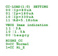
If CC-LOAD is "11", it is configured as a UFP; otherwise, it is a DFP.
VBUS IMAX INDECATION only takes effect in DFP mode, indicating that the current capability of the broadcast TYPE-C is
330uA corresponding to 3A for "10".
PDF_160 - USB-A to USB-C Development Board in VL16X Environment.zip
Altium_160 - VL16X USB-A to USB-C development board.zip
PADS_160 - A USB-A to USB-C development board for VL16X environments. (zip)
BOM_160 - USB-A to USB-C Development Board under VL16X Atmosphere.xlsx
91691
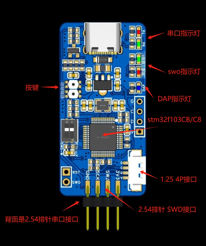
Supports DapLink/STLink/JLink programmers
The DapLink/STLink/JLink programmer has been optimized and redesigned based on open-source solutions and personal usage habits. Each firmware version and driver has been tested. Indicator lights, power output switching, a reset button, anti-backflow Schottky diodes, and self-resetting fuses have been added.
Common programmers used for programming ARM core microcontrollers include ST-Link, J-Link, and DAP-Link.
Hardware Design:
1. Uses a Type-C interface, adds indicator lights, power output switching, a reset button, anti-backflow Schottky diodes, and a resettable fuse.
2. Two SWD interfaces: Interface 1 uses a 2.54mm pin header, with the common pinout as 3V3--SWD---SCK---GND. Interface 2 uses an MX1.25-4p connector (purchased with a 16-15 coupon). This design utilizes
three solutions, all supporting virtual serial ports. It allows for direct programming and serial port debugging.
4. The pin configuration is compatible with ST-Link, J-Link, and DAP-Link.
Component availability, price, and soldering difficulty:
1. Common components are used, mostly obtainable from platform vendors with a 16-15 coupon, reducing personal DIY costs. (Thanks to LCSC!)
2. The components are arranged somewhat densely, requiring a steady hand for soldering. Solder paste and heating plate are relatively simple.
Apply solder

paste, mount the components, and place them on the heating plate. Key point

complete

!!!
Firmware burning and testing
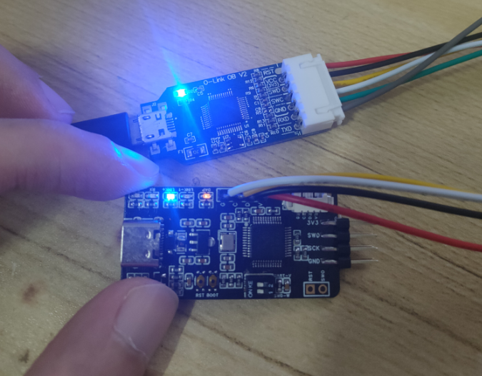
: First, the ST-Link firmware is burned: Two versions are used depending on whether F103CBT6 or F103C8T6 is used.
Version 1: STMF103CBT6, 128k flash version, burning STLinkV2.J28.M18_CB.bin firmware
. I used my old programmer to burn the new one;
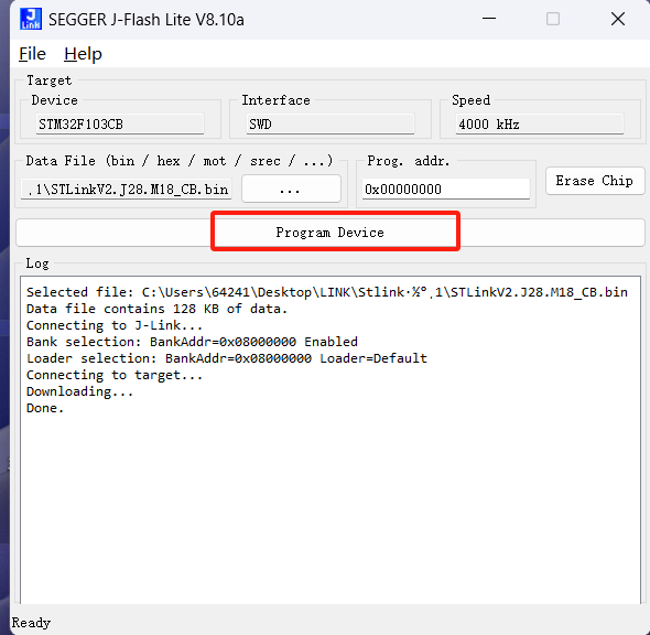
opened J-flash Lite
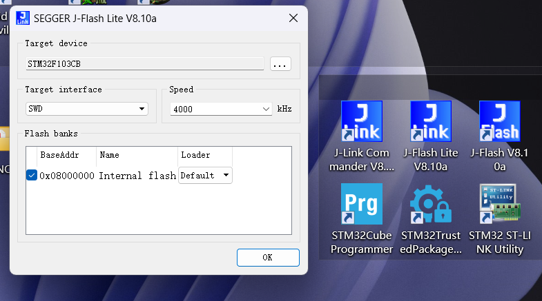
, selected firmware, clicked burn, and the burning was successful.
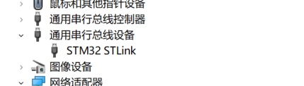
Connect the new programmer to USB; the Link+ LED will stay on. Device Manager will display an STM32 STLink serial bus device.
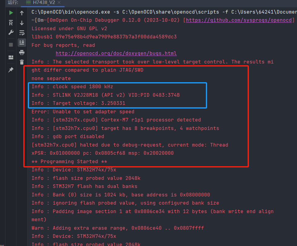
Testing was performed using OpenOCD configured in the CLion IDE development environment. The ST-Link information was successfully displayed, the firmware version was v2, and the burning was successfully recognized.
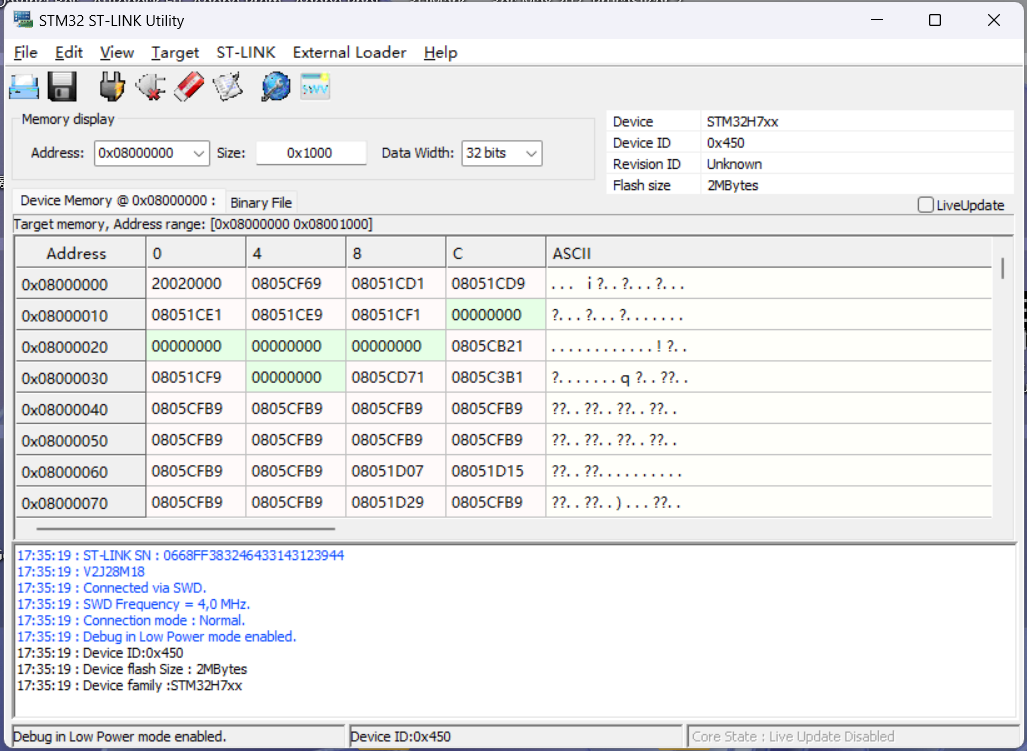
The test used ST's official programming tool, ST-LINK Utility, and successfully connected, recognized the MCU core, and successfully programmed it. (Note: The SWD interface must be connected to the MCU to be programmed for a successful connection.)
The new version of ST's official programming tool, STM32CubeProgrammer, also successfully connected and recognized it. (Note: The SWD interface must be connected to the MCU to be programmed for a successful connection.)

Firmware upgrade:
Using the upgrade tool included with the new version of ST's official programming tool, STM32CubeProgrammer,
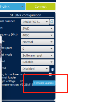
the firmware was upgraded based on this version. Click "Open in update made" several times until the new firmware version appears, then click "Upgrade" to complete the upgrade. The upgraded firmware version is V2J45M30.

Now you can happily use ST-LINK.
It can be directly recognized and used in various IDEs without changing the driver. However, the J-Link solution requires driver switching in the OpenOCD and J-FLASH IDEs. The following describes the firmware programming and testing of the J-Link solution.


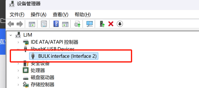
When the program driver is J-Link, the device displays as J-Link driver. At this time, official supporting programs such as J-FLASH can be used,


but the CLion environment's OpenOCD will not recognize J-Link. In this case, the driver needs to be changed

to libusdk. The first time using it, you need to use Zadig to change the program; afterwards, you can directly update and switch the driver in Device Manager.
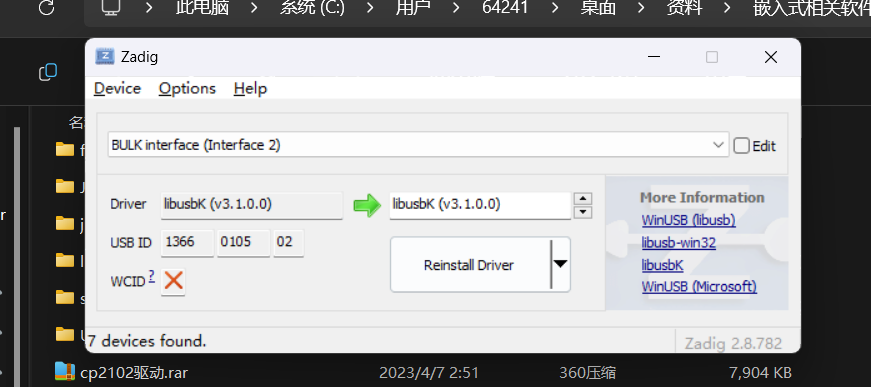
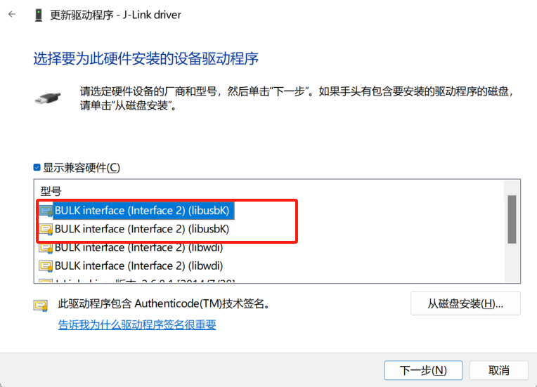
After updating to the libusdk driver, CLion OpenOCD can recognize and program normally. If you need to use J-Flash, you need to switch the driver back to J-Link. (To avoid this pitfall!!)

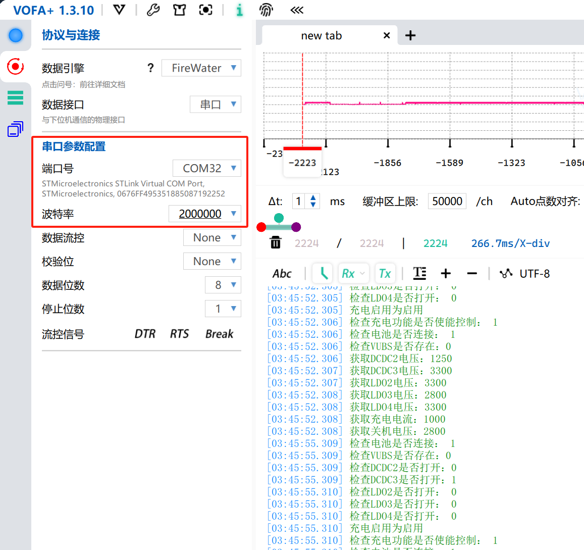
Serial port tests for both ST-Link and J-Link solutions are normal. The serial port baud rate is set to a maximum of 200000 for stable output.
----Recommended simple connection schemes for SWD:
Self-programming. For the through-hole type, design a 4-pin header interface on the edge of the board, as close to the edge as possible, with the distance from the center of the hole to the edge of the board less than 2.3. This PCB layout is generally easy to achieve.
To facilitate direct programming, pay attention to the pin order. If the interface is located on the right or top of the board, the pin order is GND--SCK--SWA---3V3; the order is reversed on the left and bottom. Otherwise, direct programming via the pin header will be impossible,
or the pins may be blocked by the serial port header. In this case, a programming cable will be required.

STLinkV2.J28.M18_CB.bin
JLink-ob V21_C8.bin
CMSIS_DAP_C8.hex
STM32 ST-LINK Utility v4.6.0_setup.zip
JLink_Windows_V810a_x86_64.zip
PDF_Supports DapLink, STLink, and JLink programmers.zip
Altium programmer that supports DapLink, STLink, and JLink solutions. (zip file)
PADS_Provides a programmer that supports DapLink, STLink, and JLink solutions. (zip file)
BOM (Bill of Materials) supports DapLink, STLink, and JLink programmers. (xlsx)
91693
Encoder module
The encoder module can count the number of times.
This is a rotary encoder module:
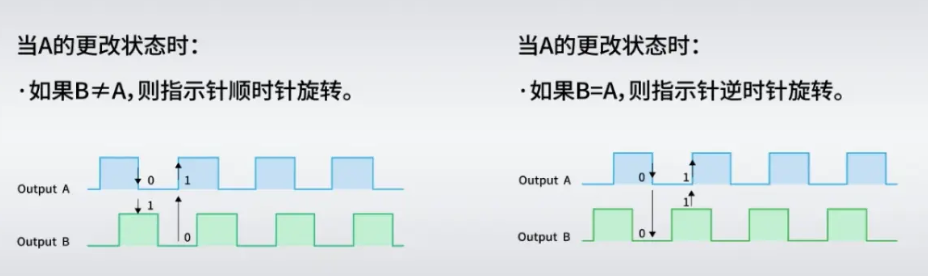
The basic internal schematic is as follows:
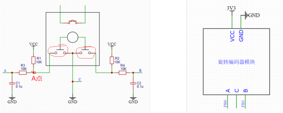
The two unconnected pins at the top are a switch, which is the switch used when the encoder is pressed down. It can be connected to the circuit if needed.

The principle is as follows:

The physical diagram is as follows:

The schematic diagram is as follows: My switch pins D and E are not connected; you can connect them based on my schematic diagram if needed.

The 3D diagram is as follows:

PDF_encoder module.zip
Altium_encoder_module.zip
PADS_encoder module.zip
BOM_14.EncoderModule.xlsx
91695
Ultra-small and easy-to-use current and voltage meter
Thanks to @wffg for the open-source project. This project is characterized by its extremely small size, lack of a USB-C port, and low cost.
This is a cloned and modified version of the simple ammeter project by @wffg, with only the PCB modified. Thanks to the open-source
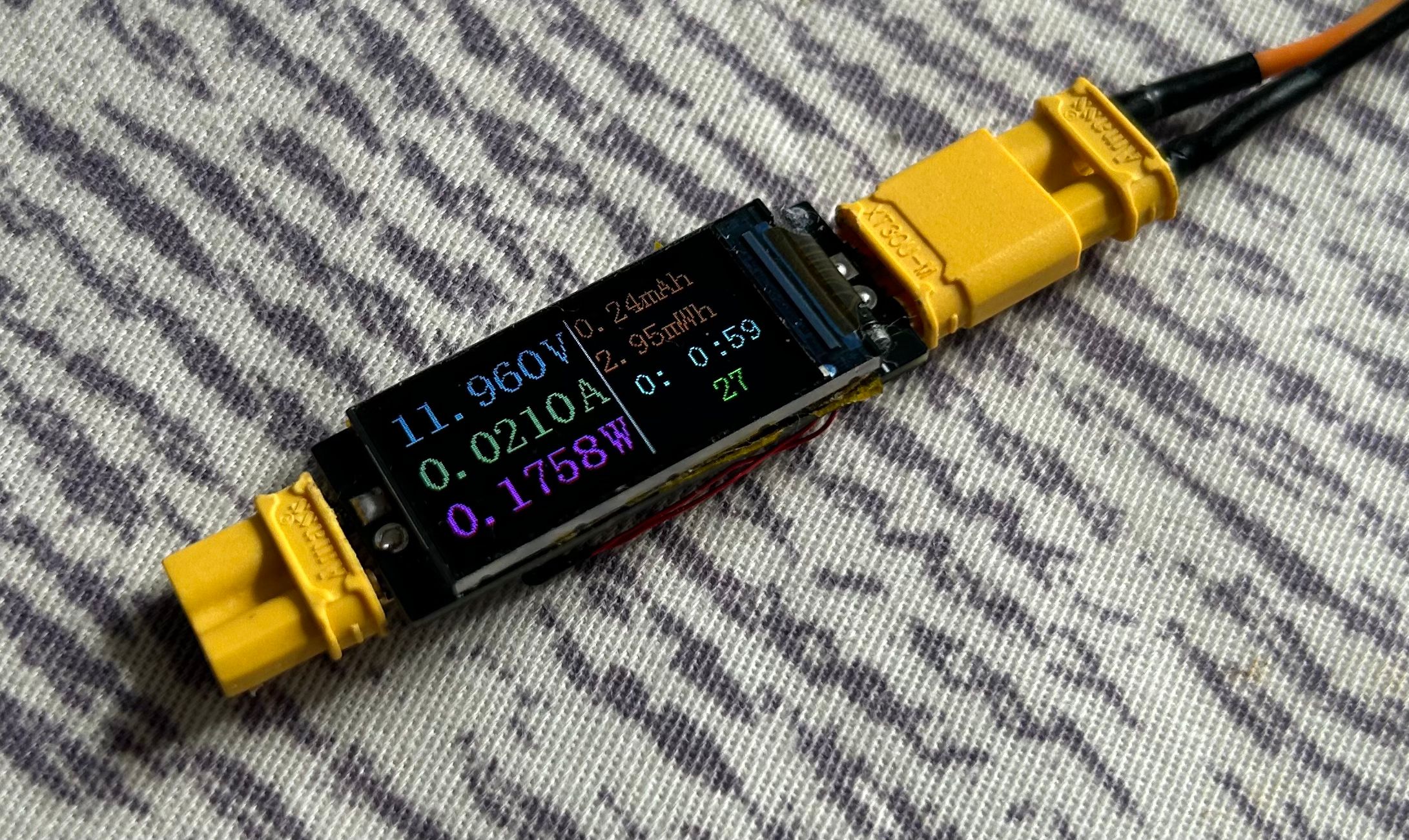
project for its features:
ultra-small (only the size of a 0.96-inch TFT screen)
, minimalist design, no CC port (can be used as a meter head),
inexpensive, and needs no further explanation
. Notes on replicating:
When soldering the TFT screen, each pin needs to be soldered individually; the temperature should not be too high;
the back of the screen needs to be insulated; the windowed area needs to be tinned to meet overcurrent requirements.
For the BOM (Bill of Materials), please be sure to open the schematic and purchase the meter yourself.
Except for the sampling resistor, all resistors and capacitors use 0603 for easy soldering.
See the original project for more details.
jdf9.hex
PDF_Miniature and Simple Current and Voltage Meter.zip
Altium_Miniature Simple Current and Voltage Meter.zip
PADS_Ultra-small and easy-to-use current and voltage meter.zip
BOM_Ultra-small and easy-to-use current and voltage meter.xlsx
91696
LED current limiting resistor selection test
Visually observe the corresponding LED brightness under different sizes of current-limiting resistors.
In engineering applications, LEDs are often used to indicate the operating status of a PCB, such as power-on and communication. However, a troublesome problem is that improper selection of the current-limiting resistor can result in LEDs that are too bright or too dim, severely impacting the visual experience (especially being blindingly bright). The purpose of this board is to visually demonstrate the corresponding LED brightness under different current-limiting resistor sizes, manually adjust it to a satisfactory brightness, and then apply it to my own project.
3ab6c4eaaa8ffc6a26f802cbc80f204f.mp4
PDF_LED Current Limiting Resistor Selection Test.zip
Altium_LED Current Limiting Resistor Selection Test.zip
PADS_LED Current Limiting Resistor Selection Test.zip
BOM_LED Current Limiting Resistor Selection Test.xlsx
91697
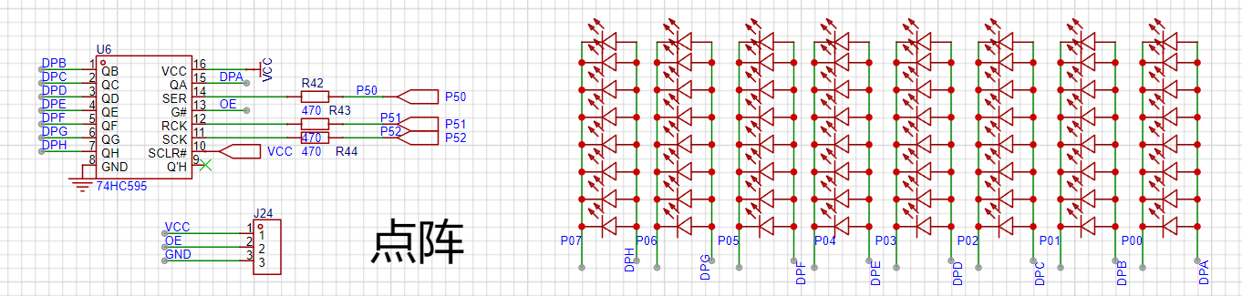
STC32 Development Board
Learn how to use STC32G12K128
Introduction:
This project is a learning board based on the STC89C51/52 microcontroller. It features a USB direct programming port, infrared, dot matrix, motor driver, LCD, OLED, buzzer, NRF24L01 interface, DS18B20 module, and digital tube circuitry.

Functionally,
this design is based on the STC89C51/52 microcontroller. It has four independent buttons, all with customizable functions. Pins are brought out using headers. Most circuit modules can be used simultaneously.


Appropriate screen learning

software can be selected according to requirements. The software code
is included in the project attachments.
BOM_Board1_Schematic1_2024-10-14.xlsx
Program source code (2).zip
PDF_STC32 development board.zip
Altium_STC32 development board.zip
PADS_STC32 development board.zip
BOM_STC32 development board.xlsx
91698
ESP32-C3FH4 Development Board
Development board based on Espressif ESP32-C3FH4
This development board is based on the Espressif ESP32-C3FH4 microcontroller, with a 160MHz main frequency, 4MB of built-in Flash memory, an onboard ceramic antenna, and a USB port on the C3 microcontroller for programming. Its dimensions are 27.95*36.6mm. All resistors and capacitors on the board are 0603 packages for easy manual soldering.
To ensure signal quality, please select the free 3313 ±20% impedance control
. [Images: ![IMG_20241013_133730.jpg]
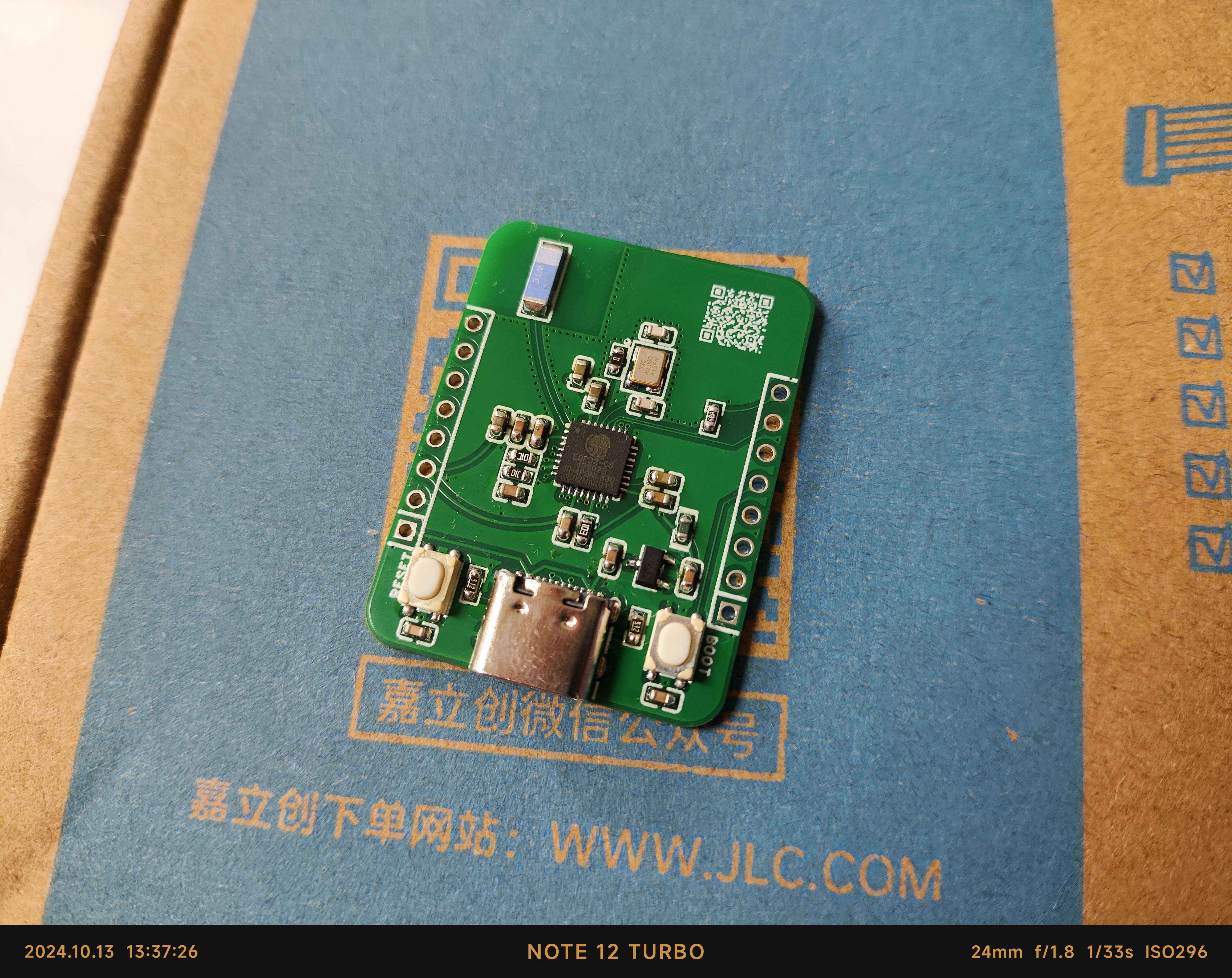
![IMG_20241013_130954.jpg]]

Pin diagram: [Image:
![3D_PCB26_2024-10-13.png]]
PDF_ESP32-C3FH4 development board.zip
Altium_ESP32-C3FH4 development board.zip
PADS_ESP32-C3FH4 development board.zip
BOM_ESP32-C3FH4 Development Board.xlsx
91699
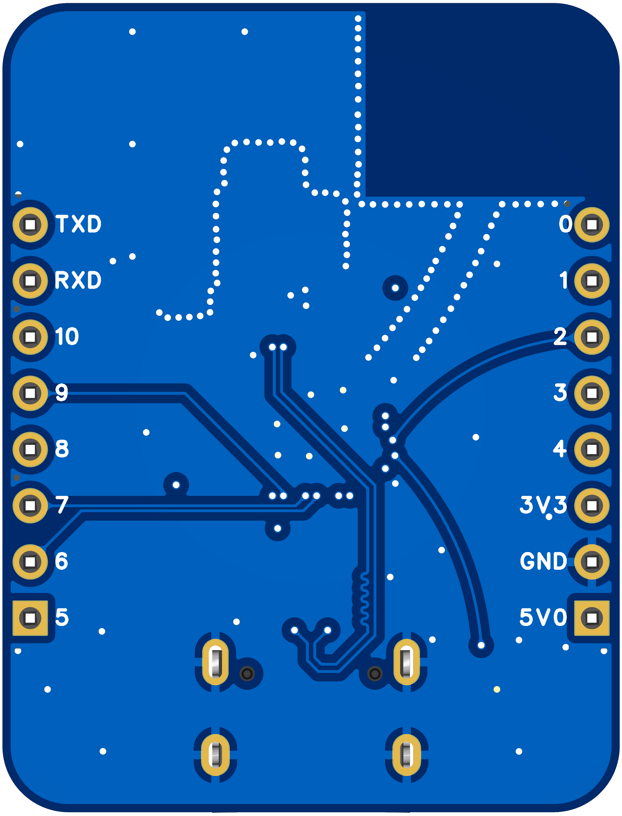
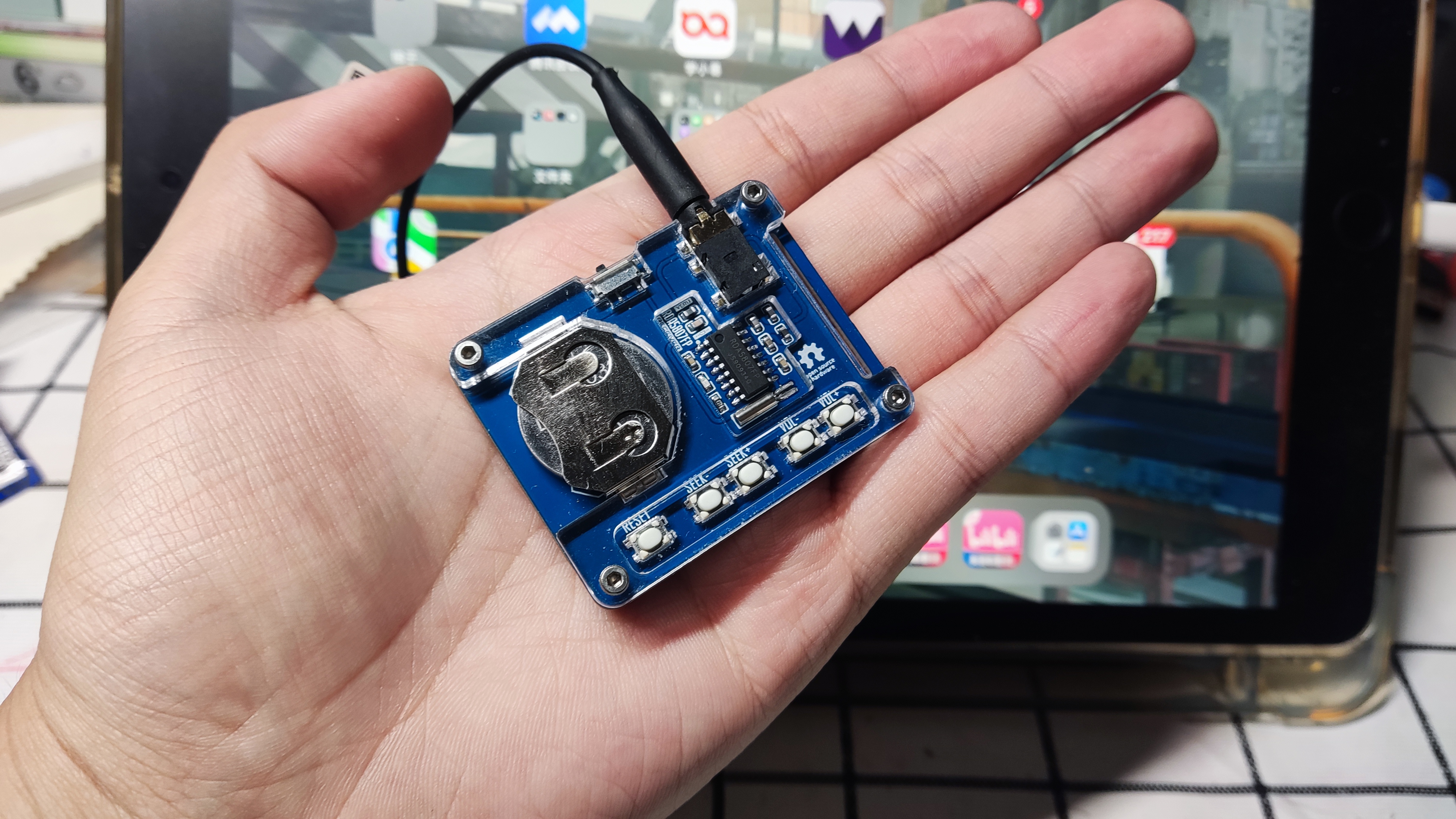
RDA5807FP Card Radio - VERITAS
This mini card radio, based on the RD5807FP, has undergone peripheral optimization and can receive FM frequencies using headphones as an antenna. The direct output sound is still quite pure.
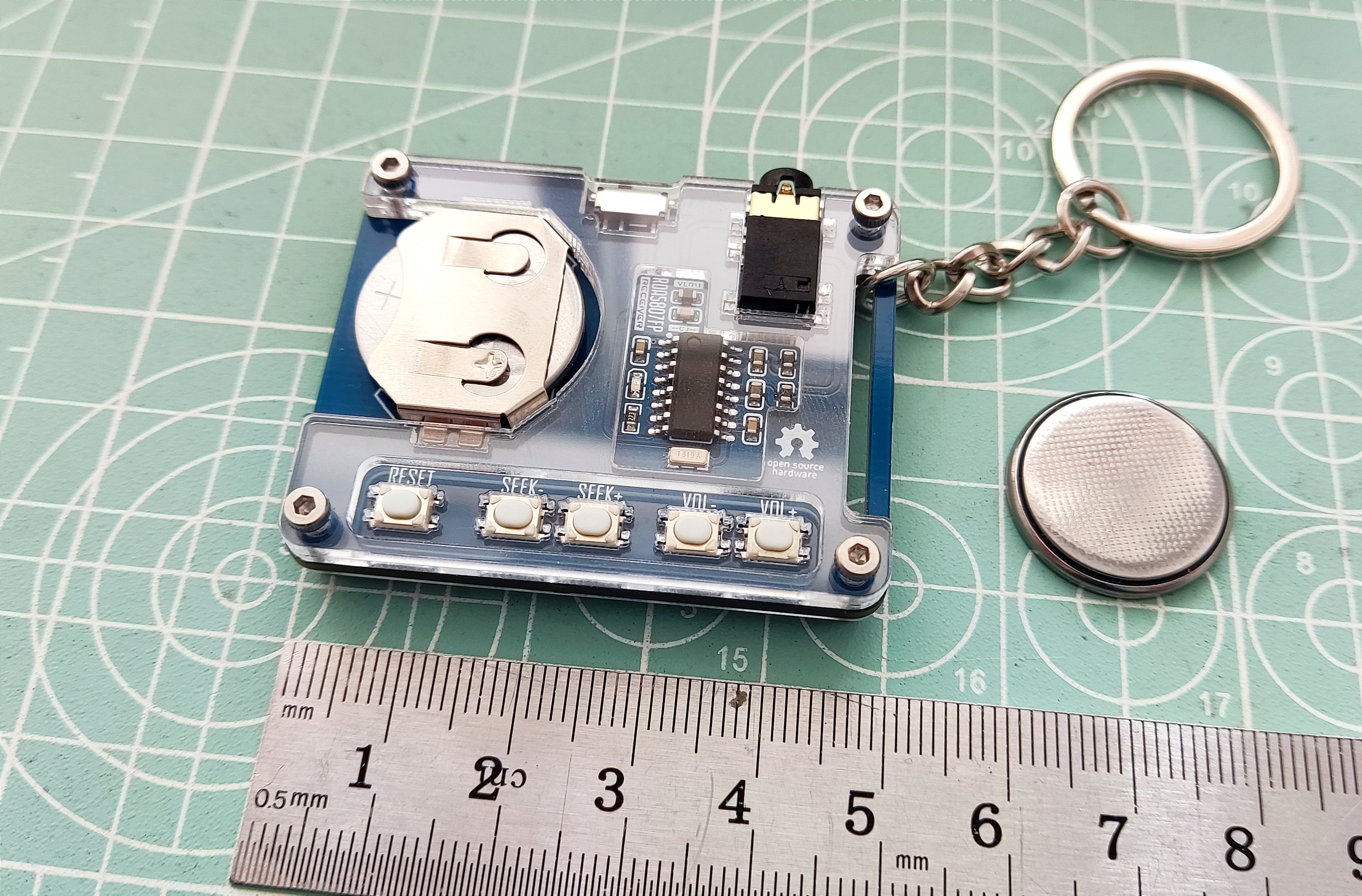
This project is a simple RDA58087FP card radio, powered by CR2032 batteries and using an earphone cable as the antenna. It provides basic FM radio functionality.
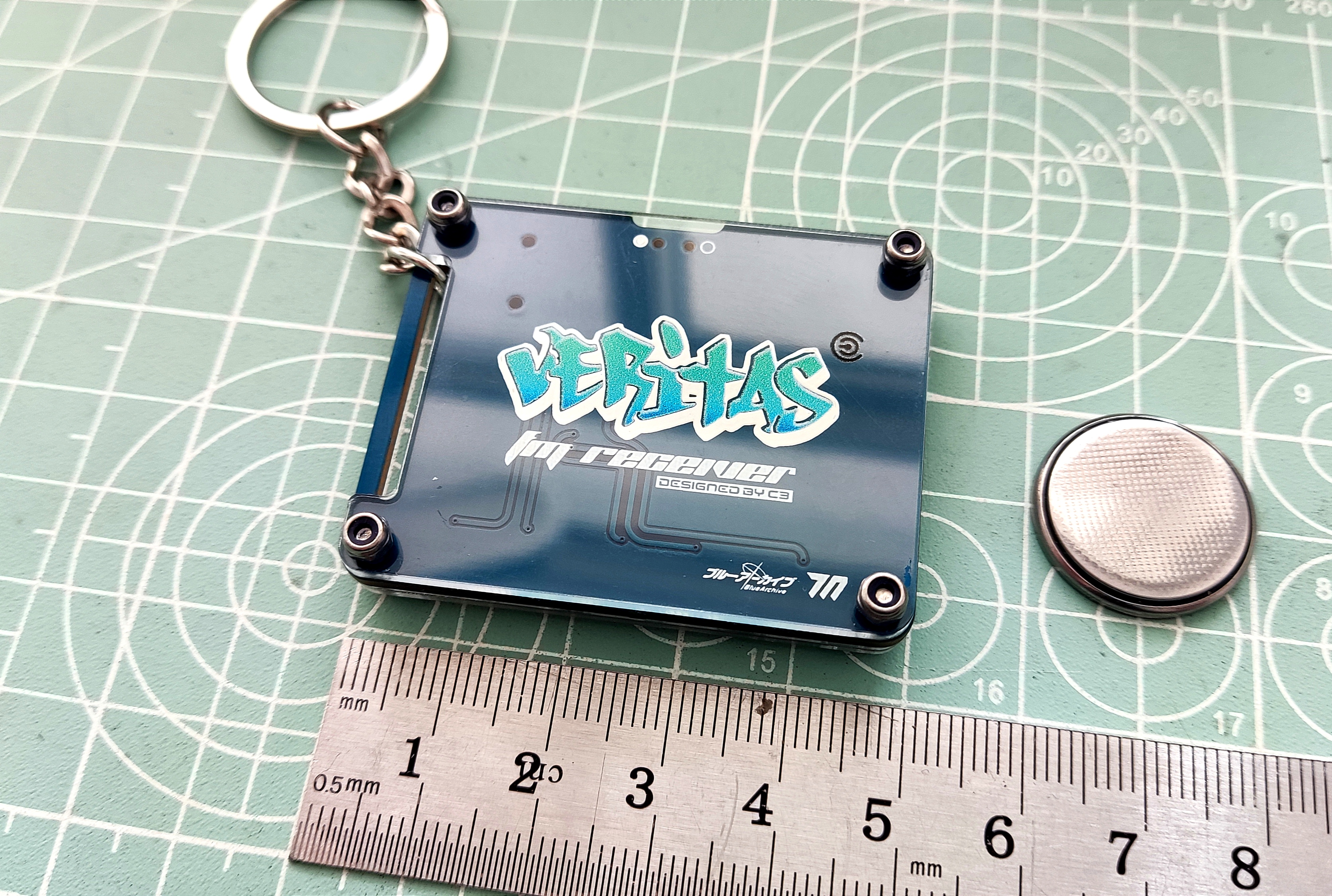
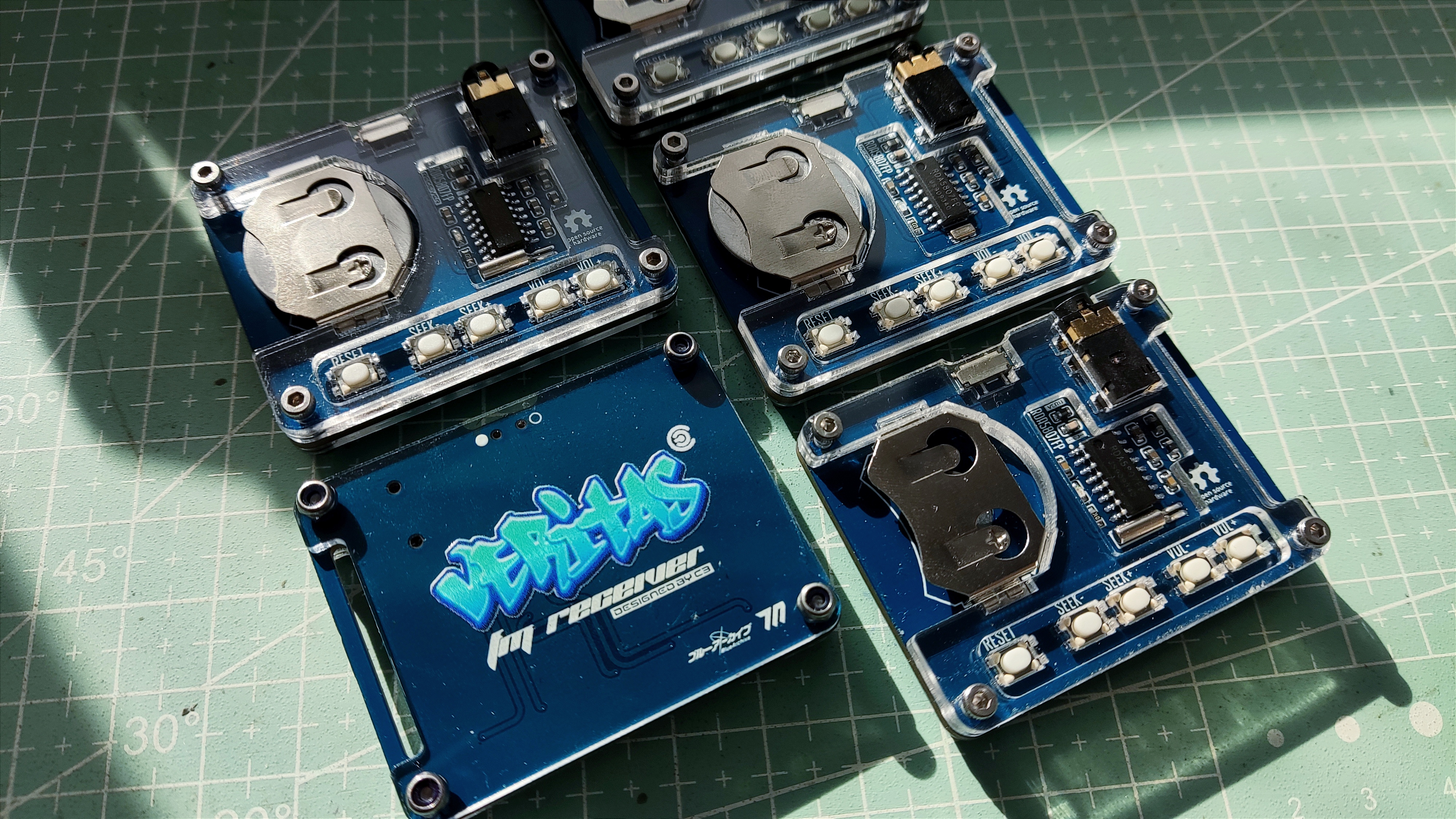
I've also added a small custom design element: a small acrylic radio keychain combining a blue-architectural Beritas-style back panel and front panel. No programming is required; simple soldering is all it takes. It's suitable for beginners practicing soldering.
Instructions: Insert the batteries and earphones, turn it on, and press seek+ or seek- to automatically search for stations. It will stop when a station is found.
Points to note: 1. It's best to use CR2032 batteries. Rechargeable batteries like LI2032 may have issues with insufficient voltage or short battery life.
2. The front panel printing thickness is 1.5mm. It's best to print from the bottom; the logo will have a glowing effect under side lighting. Thanks to LCSC for their efficient and high-quality front panel printing.
3. Saving the project may revert to the default font. Include a Gerber file in the attachment; you can edit the project with your preferred image. 4.
Hardware includes four M2x9 hex socket screws and four M2 lock nuts.
5. Custom LCSC panel is used; the file is in the project file at the bottom.
To be added.
![1728648876664.jpg]
![1728648876675.jpg]
![1728648876691.jpg]
![1728648876705.jpg]
![1728648876721.jpg]

Gerber_PCB1_Surface Mount Crystal Oscillator_Differential Buttons_Beritas_2024-10-11.zip
PDF_RDA5807FP Card Radio - VERITAS.zip
Altium_RDA5807FP Card Radio - VERITAS.zip
PADS_RDA5807FP Card Radio - VERITAS.zip
BOM_RDA5807FP Card Radio-VERITAS.xlsx
91700
electronic


 京公网安备 11010802033920号

 6A1
6A1


