For educational purposes only, not for commercial use.
This project is a temperature control device based on the STM32F103CBT6 and FreeRTOS system. Peripherals and functions used include an SPI OLED screen, TJA1050 CAN communication, CH340E serial communication, a five-way button, ADC, PID control of PWM output, IIC AT24C64 storage, CH224K PD12V decoy, and step-down.
A 3D-printed extruder head is used as a load to demonstrate the functionality. The main purpose of this project is to practice using FreeRTOS, IIC, SPI, and CAN protocols.
Code link:
https://github.com/cnxft/Temperature_Control_Equipment/tree/main
I. Overall Design Block Diagram
Power Supply:
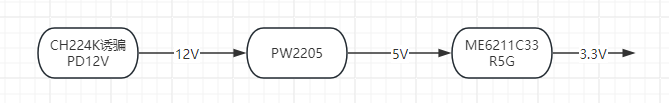
Others:

II. Hardware Circuit Composition
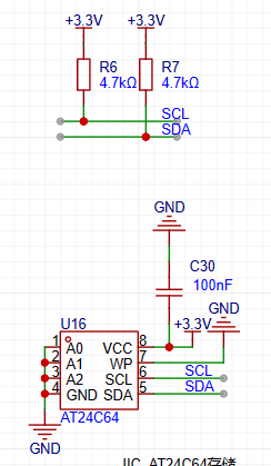
1. AT24C64 memory section, chip and its IIC pull-up
2. 12864 OLED screen SPI wiring

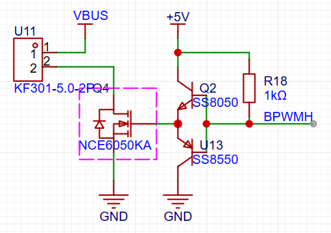
3. PWM control output size circuit
III. Program Flowchart
The following content is initialized or started before starting the FreeRTOS task scheduler:
HAL_ADCEx_Calibration_Start(&hadc1);
HAL_ADC_Start_DMA(&hadc1, (uint32_t *)&dmaadc, 3);
HAL_TIM_Base_Start_IT(&htim2);
HAL_TIM_PWM_Start_IT(&htim2, TIM_CHANNEL_1);
HAL_TIM_PWM_Start_IT(&htim2, TIM_CHANNEL_3);
NTC1save_init(ntc1save);
Key_Loading();
userShellInit();
CAN_SetFilters();
HAL_CAN_Start(&hcan);
u8g2Init(&u8g2);
A progress bar then appears on the OLED screen, its length increasing as parameters are retrieved from the AT24C64.

This project uses the FreeRTOS system, making the overall design relatively simple. A total of 7 tasks are used:
void AppTask_App(void *argument);
// Reads the NTC value and calculates
void AppTask_OutPut(void *argument);
// Calculates the duty cycle of the output PWM waveform using the PID algorithm
void AppTask_MessSend(void *argument);
// Sends CAN, serial port messages, and saves data to the AT24C64
void AppTask_SerCom(void *argument);
// Uses the shell_letter open-source library
void AppTask_CanCom(void *argument);
// Receives messages via polling CAN
void AppTask_Key(void *argument);
//Using the multi_button open-source library to generate a 5ms tick
void AppTask_Menu(void *argument);
//The program that drives the OLED screen
1. Task content
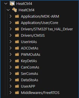
Each task is written in a file under UserApp, which you can check yourself
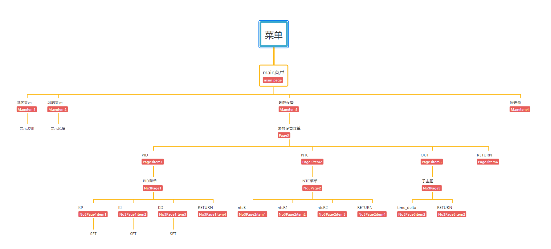
2. OLED menu division
The OLED screen uses an open-source program from a Bilibili user. The idea is to make it into a linked list, which can point to the next level menu or to the interface you want to create (function form).
A simple menu list is written
3. u8g2 initialization
The callback function for driving the OLED is written in the oled.c file. u8g2 initialization:
u8g2_Setup_ssd1306_128x64_noname_f(u8g2, U8G2_R0, u8x8_byte_4wire_hw_spi, The `u8x8_stm32_gpio_and_delay`
function indicates that 4-wire hardware SPI is used, and the SPI driver function from the HAL library is written in the corresponding position within the function.
The `u8x8_stm32_gpio_and_delay()` function is the GPIO and delay function when using software SPI/IIC. When using software, the HAL GPIO and delay functions should be written in this function, but since hardware is used here, the function directly returns 1.
Using the `setup` function built into the U8G2 library for SSD1306, there's no need to write it manually.
4. Menu switching:
When a key is pressed, the screen's running state changes, and the menu is refreshed or a specified function is opened based on the running state.
The key detection task is written in the `TaskKey` task, which generates a tick every 5ms to detect key presses. Then, the key detection results are placed in a pre-created queue.

The TaskMenu task calls the function to obtain the key status in blocking mode, with a blocking time of 200ms
(xQueueReceive(Queue_OLEDKeysHandle, &Dir, pdMS_TO_TICKS(200)) != pdTRUE)
(which can be understood as refreshing the screen every 200ms)
. 5. The
CAN interface does not have many functions or detailed operations. It only configures the following functions to send and receive normally. There are no functions
that use CAN. In the usercan.c file, the sending, polling, and filter configurations are all included.
The filter is configured in 32-bit mask mode. It will be modified later when there is a specific application.
6.
For the serial port, a letter_shell library is used, which can manipulate the device like a Linux shell.
In the shell_func..c file, several functions have been added. Commands can be used to call these functions to modify the values of kp, ki, and kd for more convenient parameter tuning.
SHELL_EXPORT_CMD(SHELL_CMD_PERMISSION(0) | SHELL_CMD_TYPE(SHELL_TYPE_CMD_FUNC), out_state, Shell_OUT, Enable output 1 or 0);
SHELL_EXPORT_CMD(SHELL_CMD_PERMISSION(0) | SHELL_CMD_TYPE(SHELL_TYPE_CMD_FUNC), out_target, Shell_Target, Set target temp double);
SHELL_EXPORT_CMD(SHELL_CMD_PERMISSION(0) | SHELL_CMD_TYPE(SHELL_TYPE_CMD_FUNC), parameter_show, Shell_Parameter_Show, show pid wushen);
SHELL_EXPORT_CMD(SHELL_CMD_PERMISSION(0) | SHELL_CMD_TYPE(SHELL_TYPE_CMD_FUNC), pid_reset, Shell_PID_Reset, pid reset wushen);
SHELL_EXPORT_CMD(SHELL_CMD_PERMISSION(0) | SHELL_CMD_TYPE(SHELL_TYPE_CMD_FUNC), kp_set, Shell_Kp, Set Kp float);
SHELL_EXPORT_CMD(SHELL_CMD_PERMISSION(0) | SHELL_CMD_TYPE(SHELL_TYPE_CMD_FUNC), ki_set, Shell_Ki, Set Ki float);
SHELL_EXPORT_CMD(SHELL_CMD_PERMISSION(0) | SHELL_CMD_TYPE(SHELL_TYPE_CMD_FUNC), kd_set, Shell_Kd, Set Kd float);
Although the parameters kp, etc., are of type double when defined, the library parameter of letter_shell is double, which will cause an error (0), while float is normal.
After connecting the serial port, you can press the Tab key or type help+enter to view the available commands. It's worth noting that when the function type is floating-point, the decimal point should not be omitted.
The logo can also be modified in the shell.c file.
See how beautifully I modified it?

7. ADC Acquisition:
Here, a formula method is used to calculate the current temperature based on the B value. The function name is: float ntc_count_value(ntcpar ntcx). This function is located in ntc.c. DMA is used to obtain the ADC value, and the ADC value is periodically obtained, calculated, and saved in AppTask_App.
8. Output
: The heating device is driven by a PWM-controlled transistor-controlled MOSFET. The PWM duty cycle is calculated by the PID algorithm. Here, the output on the left is used in conjunction with the temperature sensing resistor. The right side can use PWM to control fans, etc. The frequency division value and counting value settings are as follows. You can modify them according to your needs. When modifying the counting value, remember to modify the function that maps the PID calculation result to the PWM duty cycle part.

9. Data Storage and Retrieval
: A separate AT24C64 chip was designed to store the device parameters, including the values of kp, ki, and kd, the B value of the temperature sensing resistor, the resistance value of the voltage divider resistor of the temperature sensing resistor, the resistance values of the two resistors for voltage measurement, etc.
The data is stored on the AT24C64 chip in the following locations, including the starting address and the offset relative to the starting position.
/****************Relative address for storing data on AT24C64*******************/
#define DATE_FIRST_ADD 352 // First position for storing data
#define Date_OUTSTATE_SUM 0 // Difference from the initial position
#define Date_NTCB_SUM 1 // Relative difference 1
#define Date_NTCT25_SUM 3
#define Date_NTCMAXADC_SUM 7
#define Date_NTCR1_SUM 11
#define Date_NTCR2_SUM 15
#define Date_VADCMADC_SUM 19
#define Date_VDDA_SUM 21
#define Date_RESH_SUM 25
#define Date_RESL_SUM 29
#define Date_KP_SUM 33
#define Date_KI_SUM 41
#define Date_KD_SUM 49
#define Date_TARGET_SUM 57
#define Date_TIMEDELTA_SUM 65
#define Date_TOTAL_NUM 15
In the SaveAndRead_func.c file, two functions are defined:
HAL_StatusTypeDef Date_Init(uint8_t which_one);
HAL_StatusTypeDef Date_Save(uint8_t which_one);
These are used to save and read data respectively. A union variable is used in the functions to make saving and reading more convenient.
10. The progress bar
reads data before the for (;;) loop in AppTask_App, loading some necessary parameters into the program.
Initially, a synchronization function between programs in the FreeRTOS system was used, using notifications to simulate binary semaphores to synchronize AppTask_App and AppTask_Menu. The progress bar in the AppTask_Menu task will lengthen if it does not acquire a binary semaphore; otherwise, it enters a blocked state until the progress bar finishes and enters the menu interface.
11. Problems and Reflections
First of all, it should be said that this is not a perfect work; there are still many areas that need improvement in terms of functionality, program, and shell.
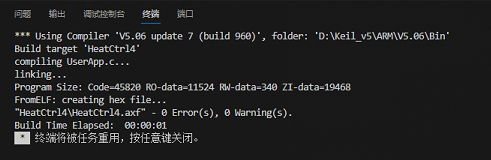
...To be continued...
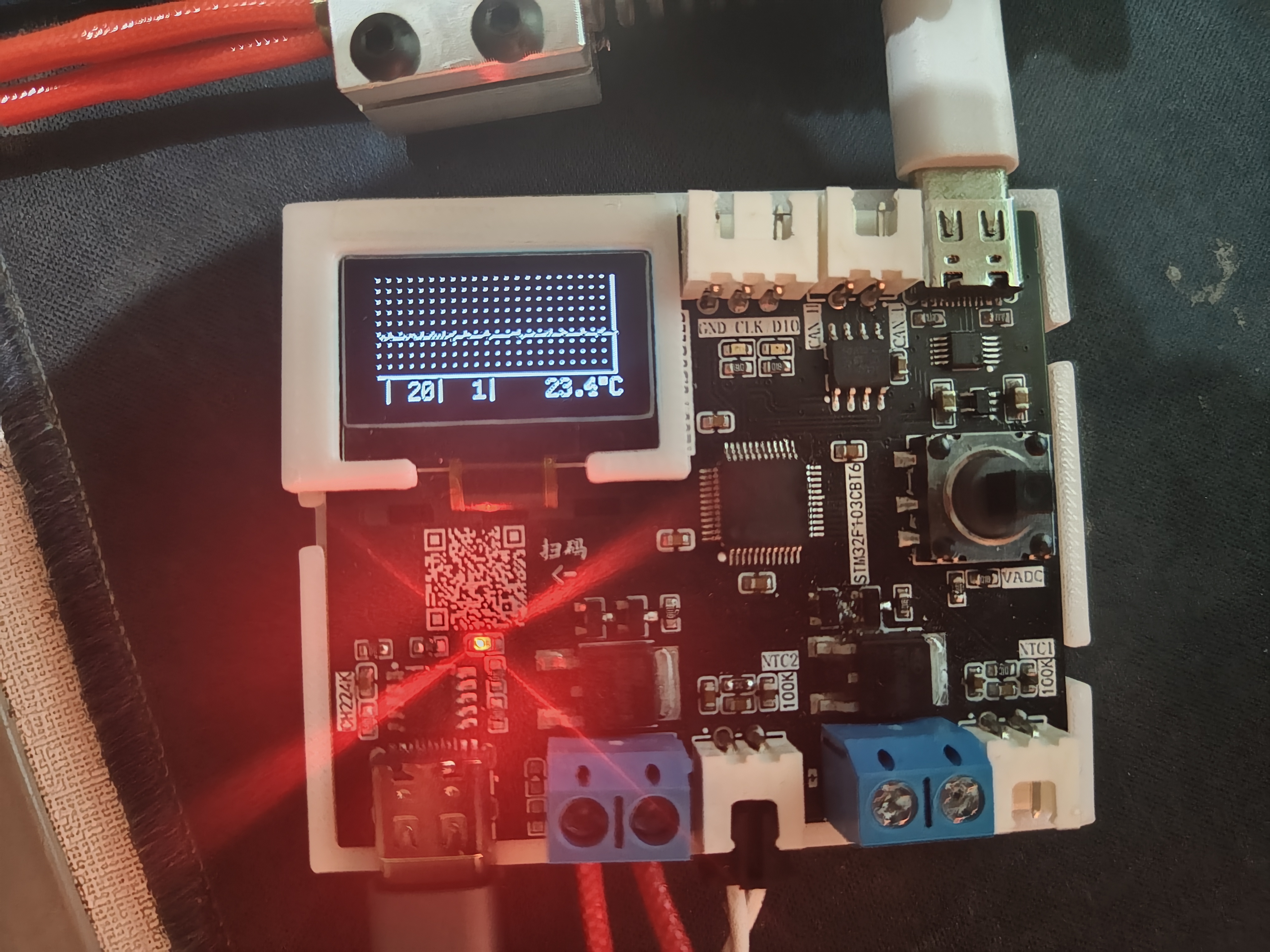
Part Four: Physical Display
My soldering sequence: First, solder the back side using a soldering station. Second, solder the chip and two Type-C connectors, ensuring correct soldering. Third, solder the rest using a hot air gun, but pay attention to the Type-C connector placement. Alternatively, you can solder the PD12V decoy section first to test the effect; a successful decoy will light up the LED. Then solder the 5V to 3.3V converter. Finally, solder the screen and plug-in components.
Temperature curve
output settings (switch, target temperature, fan PWM duty cycle)

and PID KP
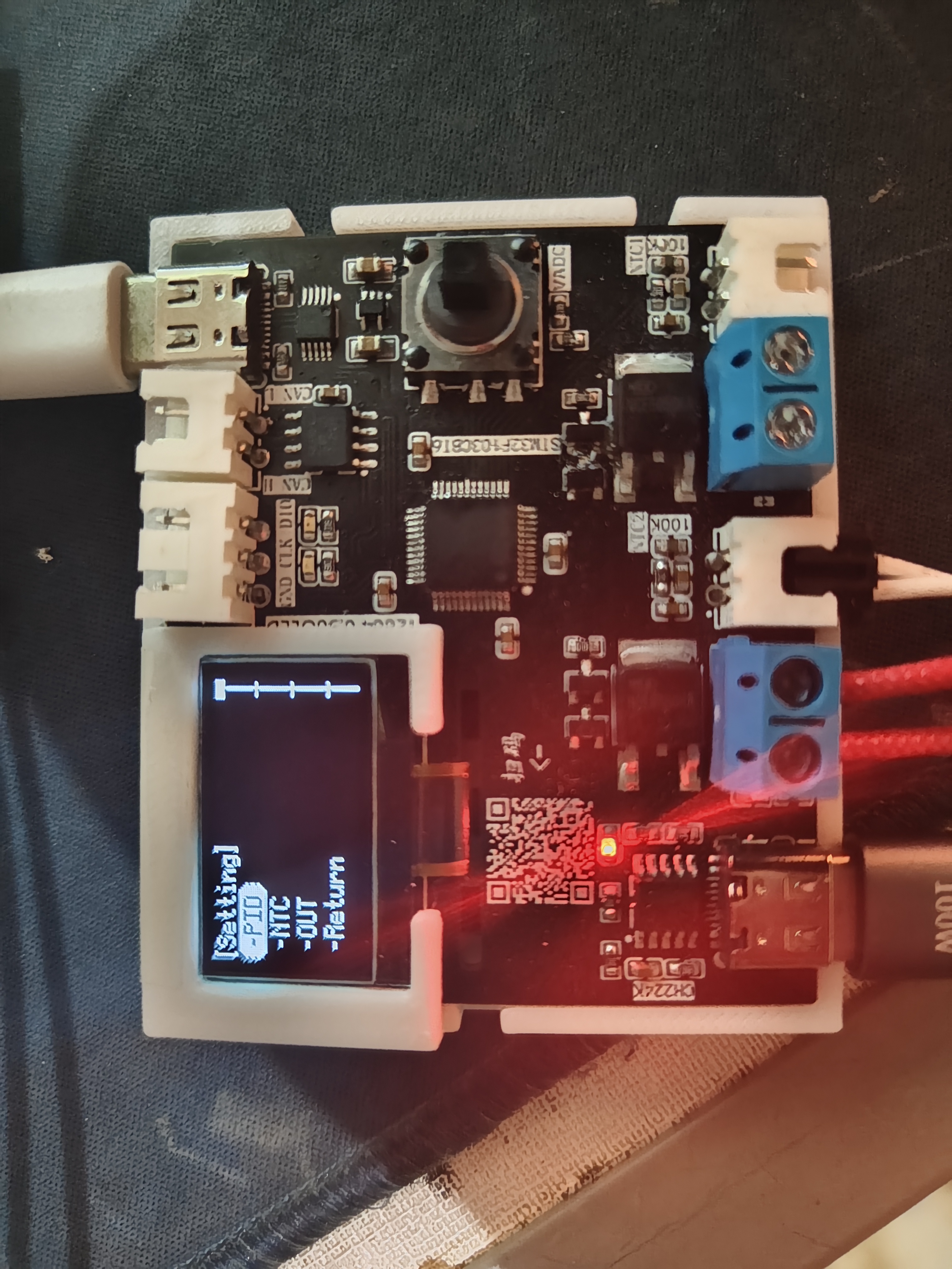
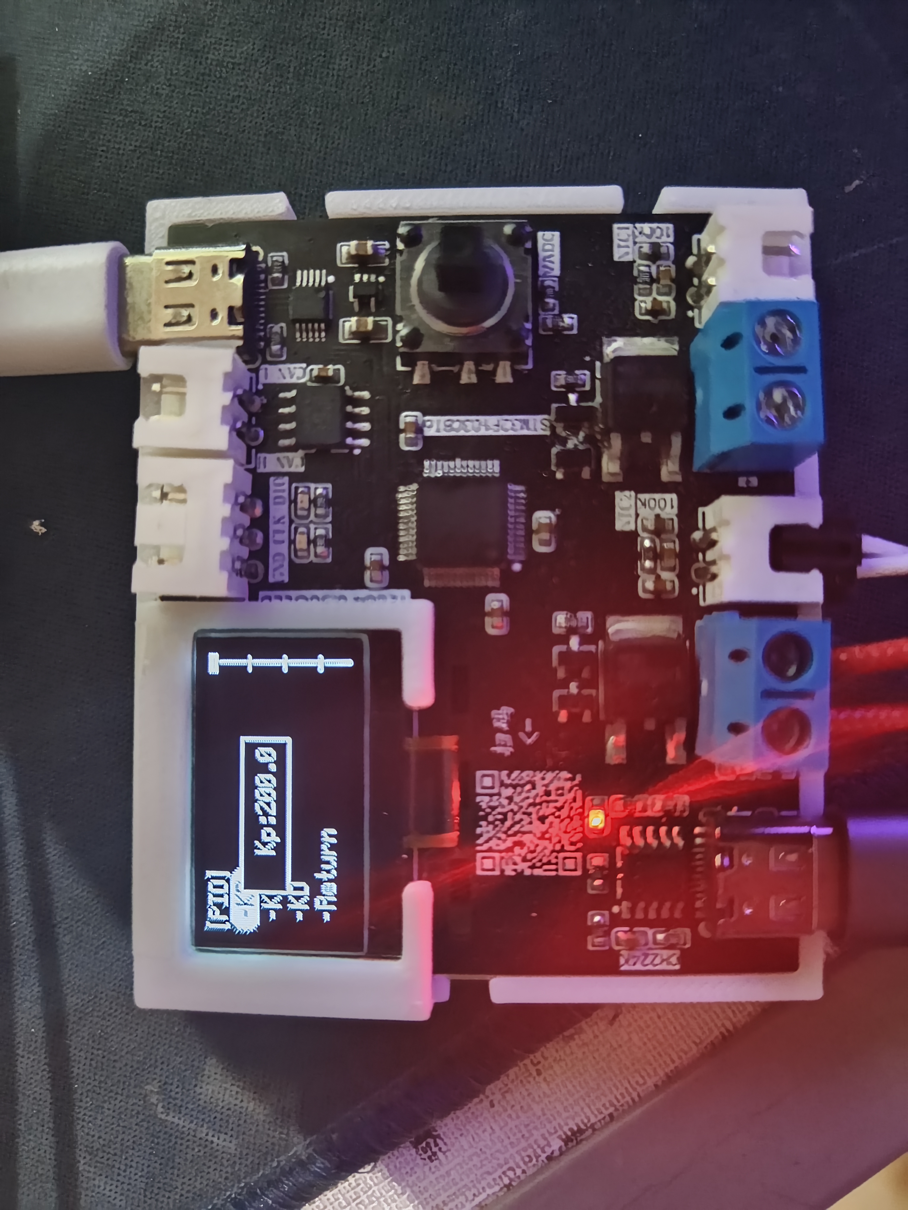
parameter display are included
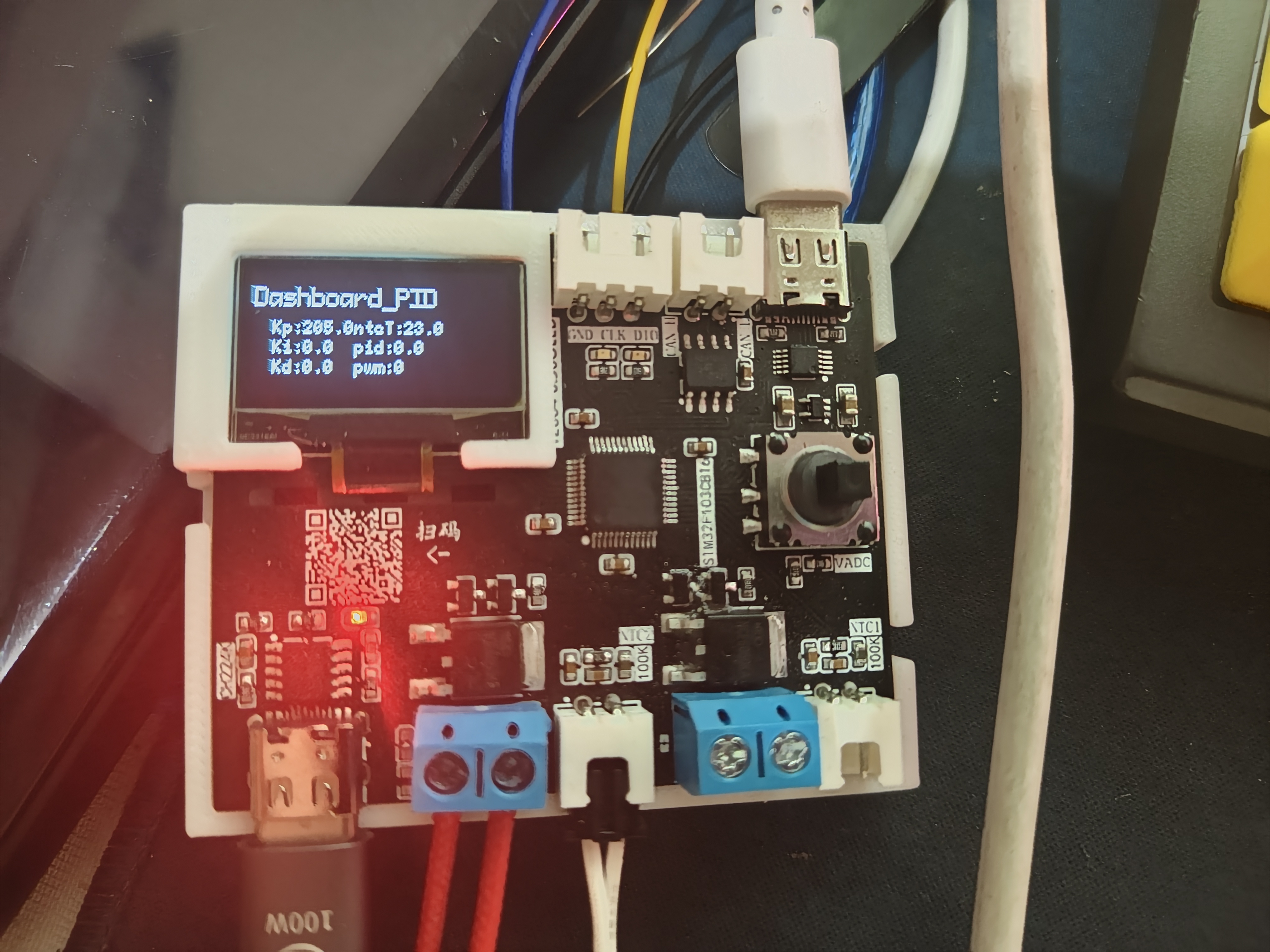

. The demonstration
video, located in the appendix, shows the usage of letter_shell and demonstrates parameter modification and automatic saving to the AT24C64.


 京公网安备 11010802033920号

 Q18.999-JXS32-12-10/100-HMR-LF


