 The demonstration video has been uploaded to Bilibili, and feedback is welcome:
 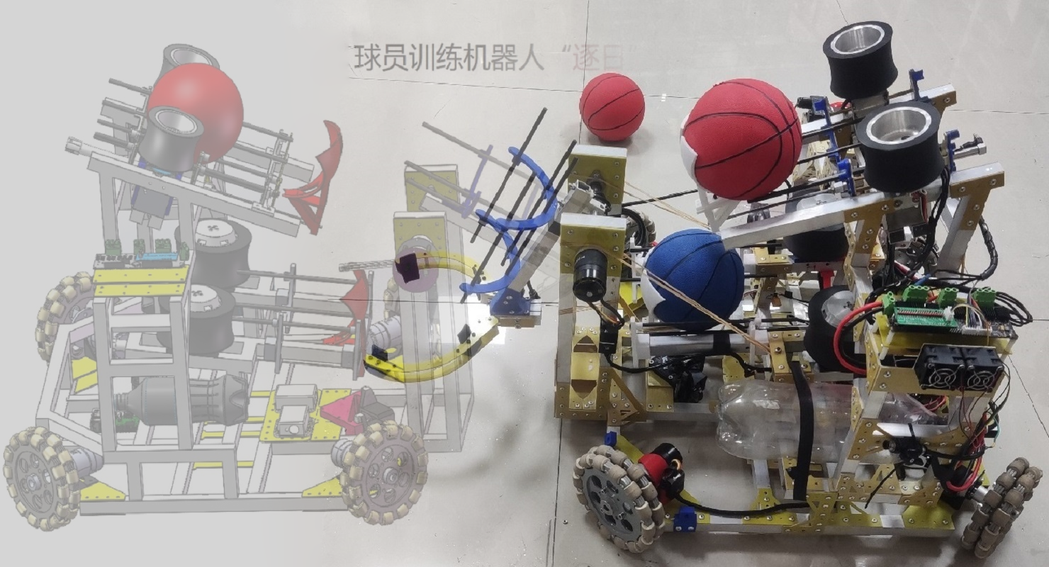 "Chasing the Sun" robot: 2.2 Overall design block diagram and model representation of the "Chasing the Sun" robot:
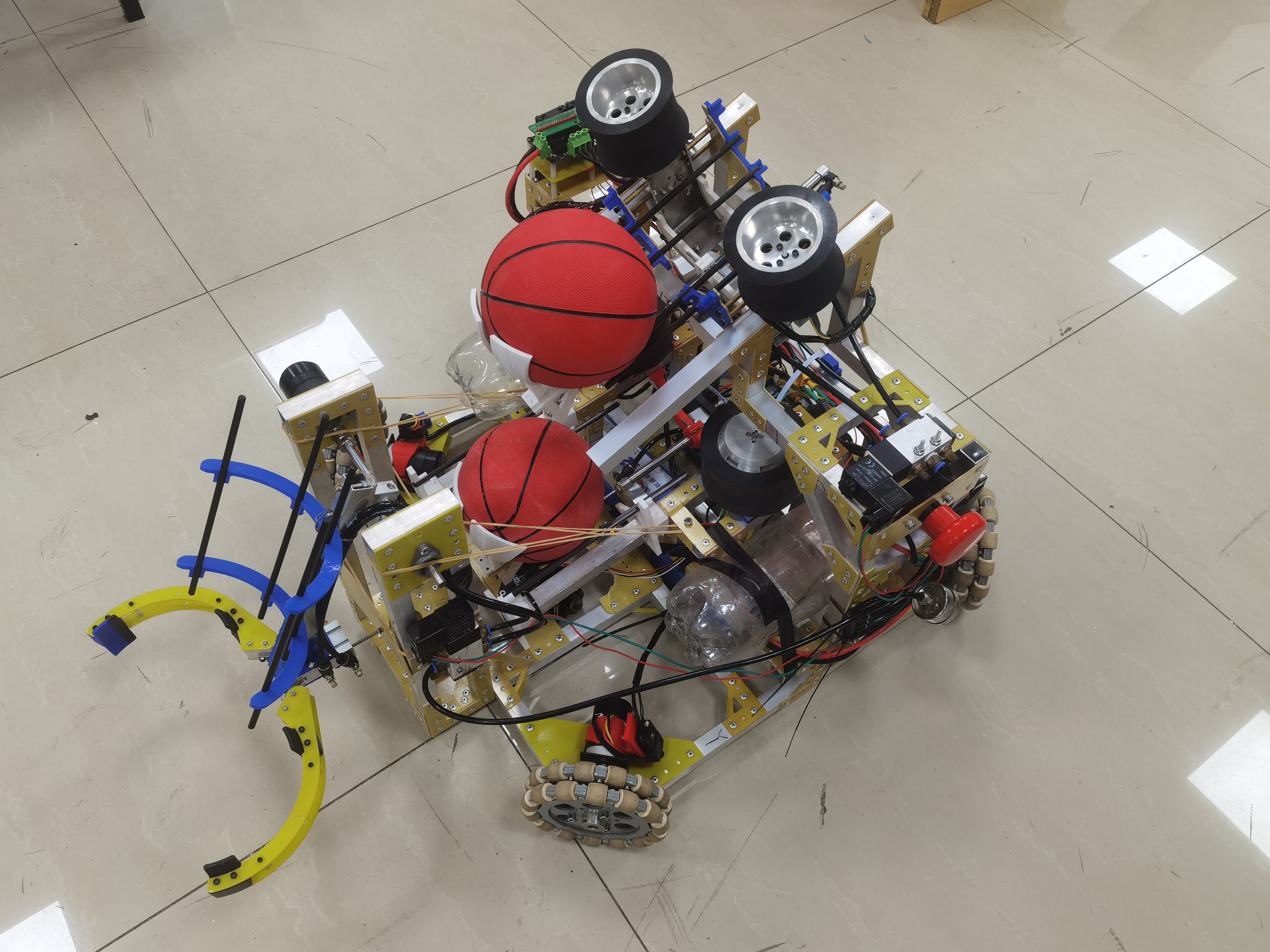
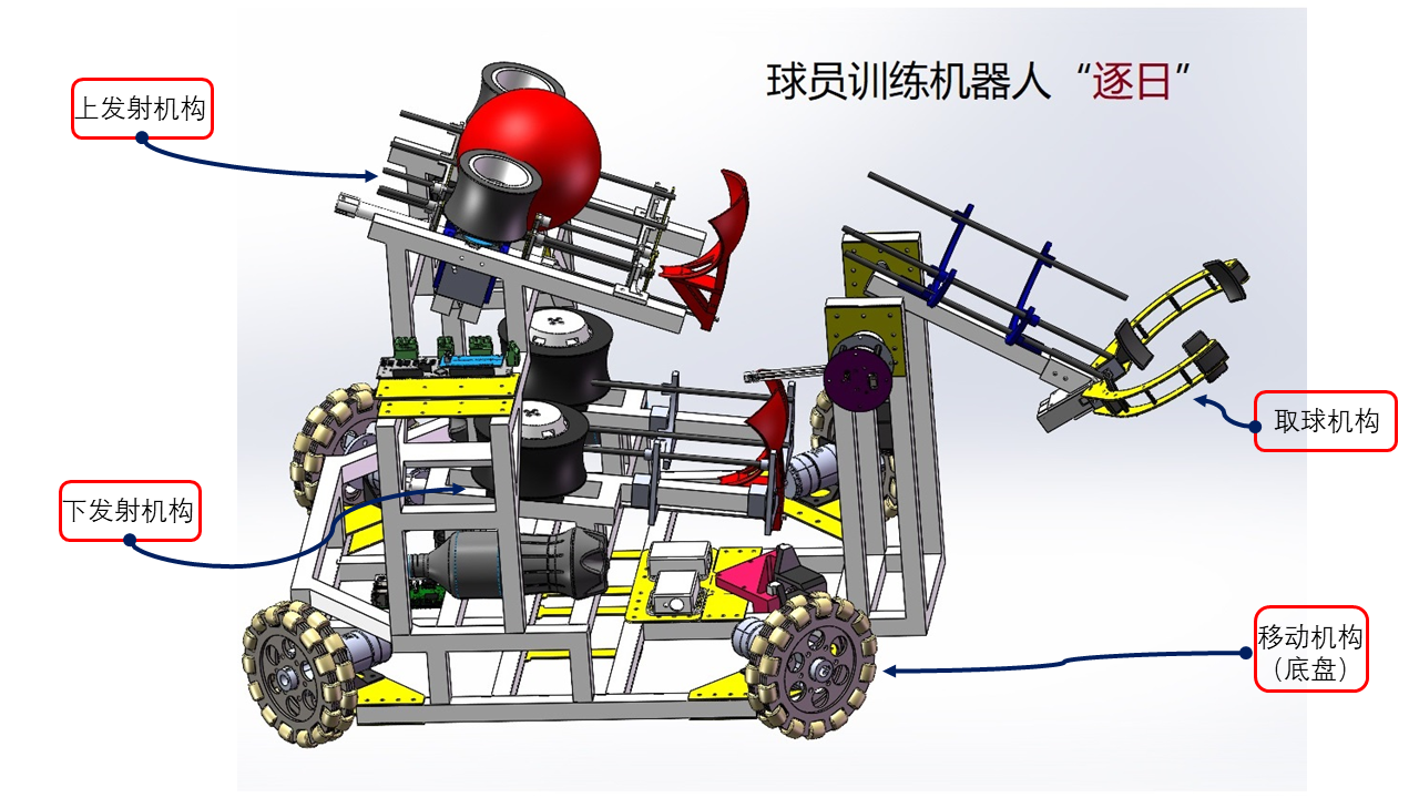
  From the two images above, we know that the robot consists of four parts: a moving mechanism (chassis), a ball-collecting mechanism, a lower launching mechanism, and an upper launching mechanism. We will explain each part below .
  1. The chassis is a relatively simple planar mechanism built from aluminum tubes. From the exploded view, we can see that the main components consist of four sets of M3508 brushless motors, a C620 motor speed controller, an omnidirectional engine wheel, and a positioning system module.
 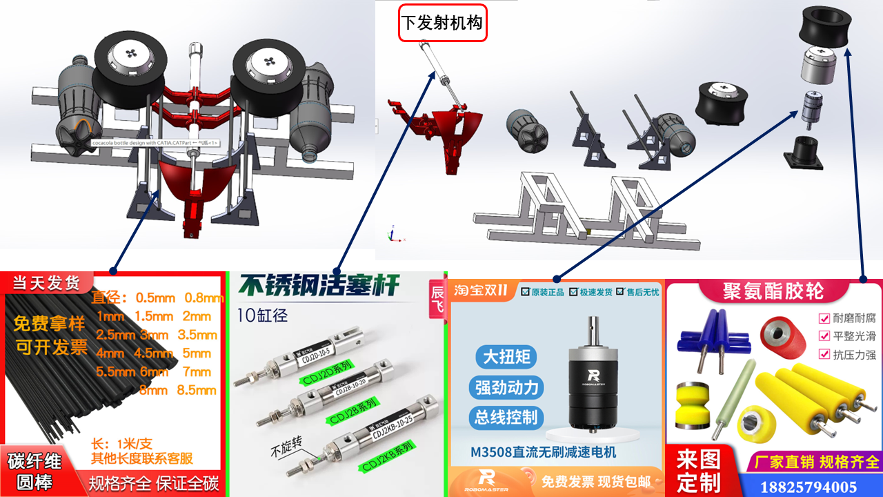 1. Aluminum tube frame;
 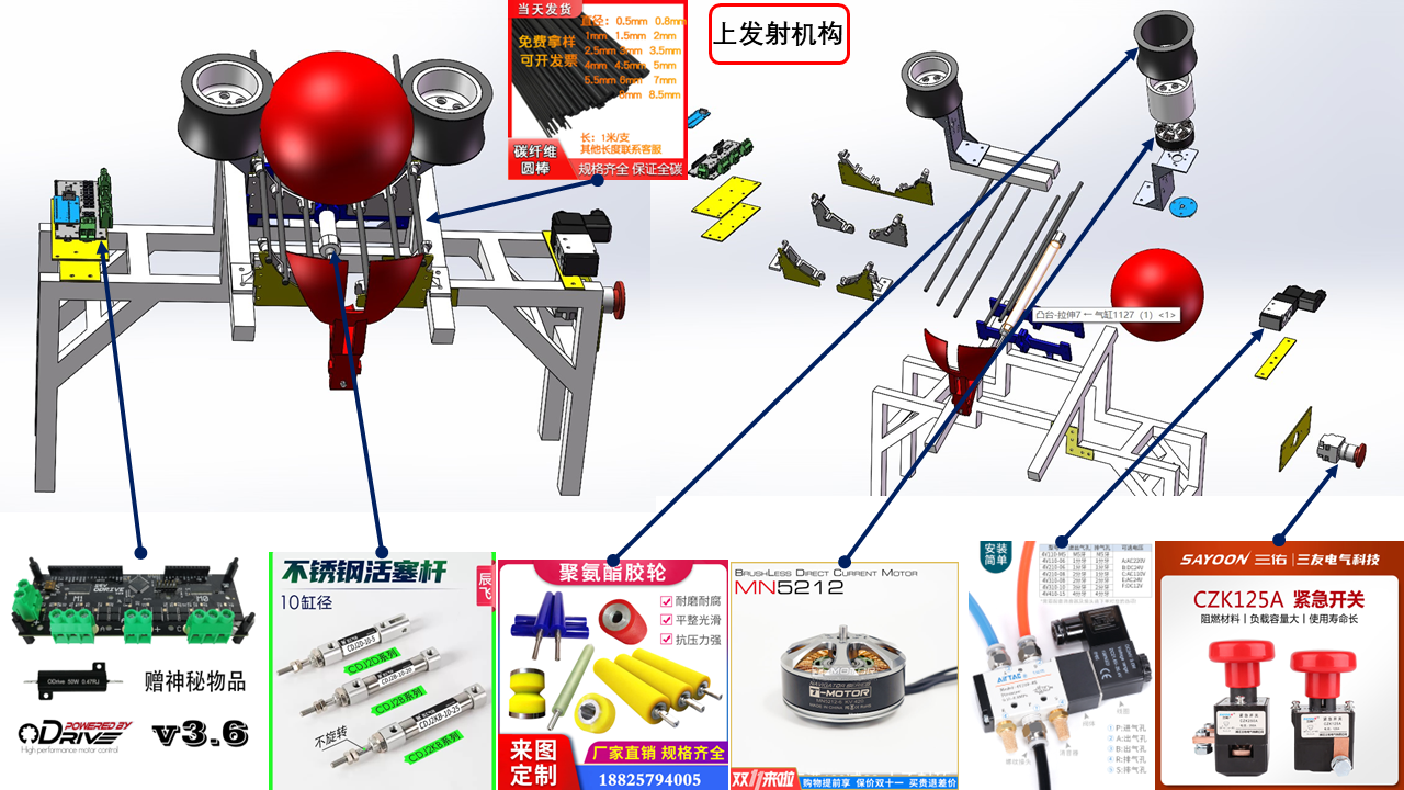 1. Aluminum tube frame;
 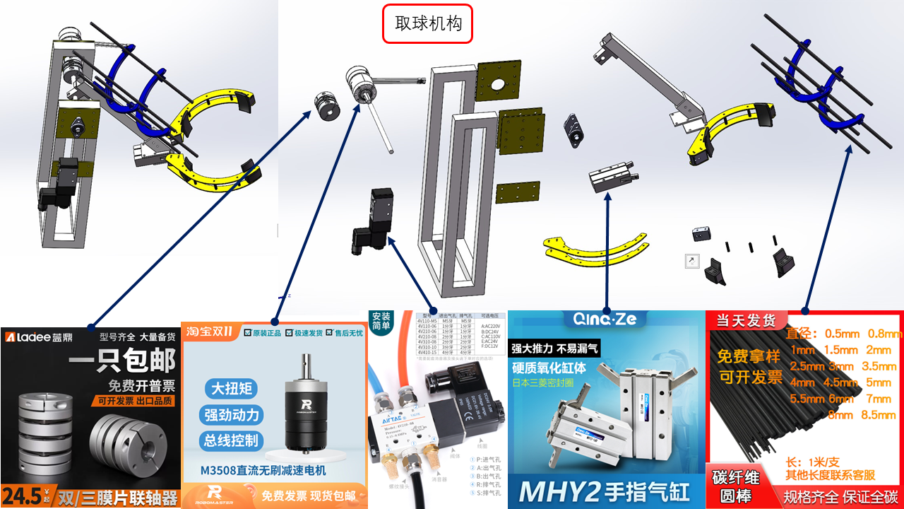 : 1. Aluminum tube frame;
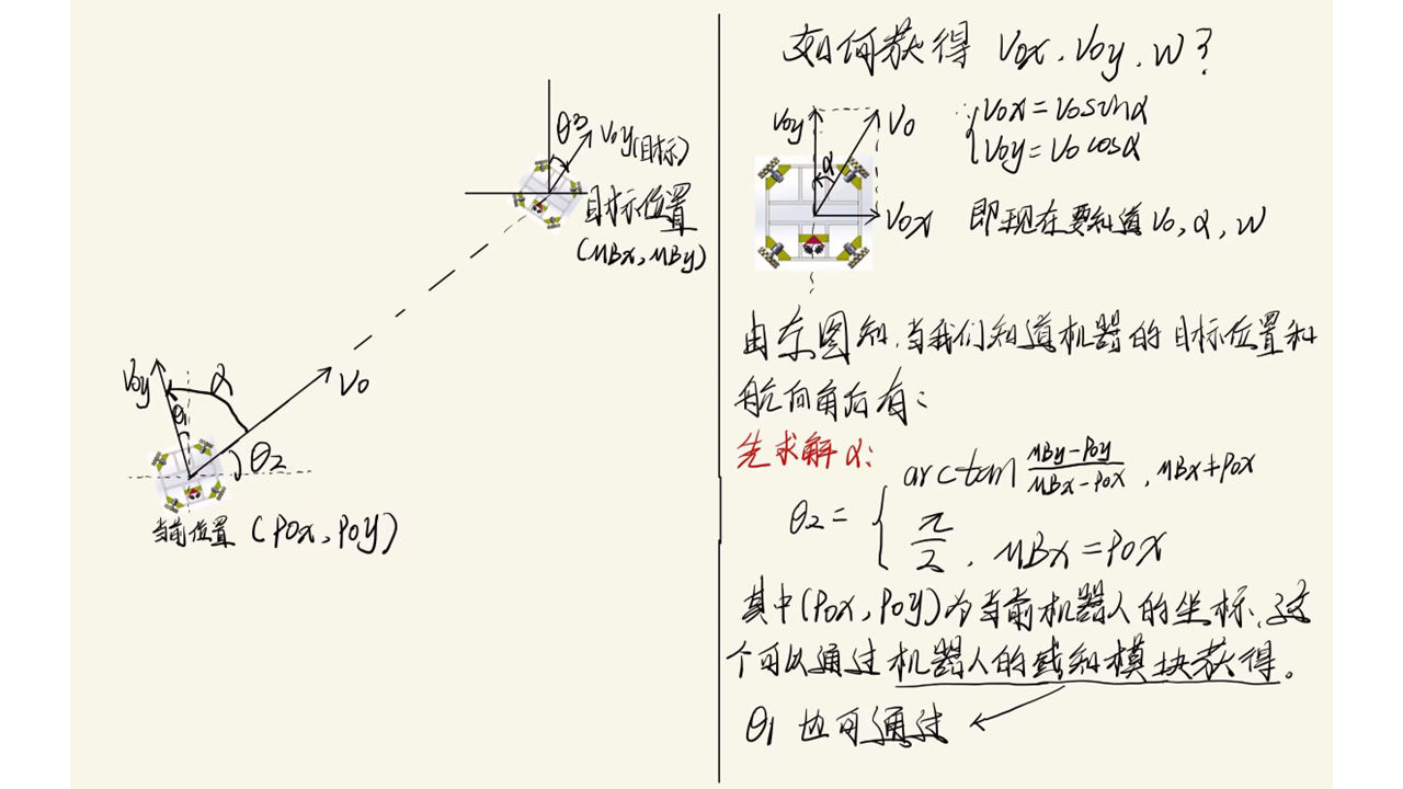
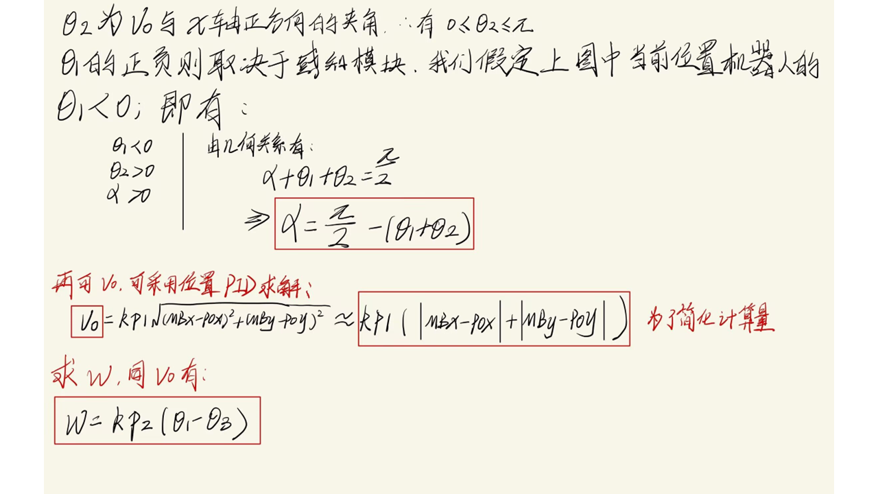
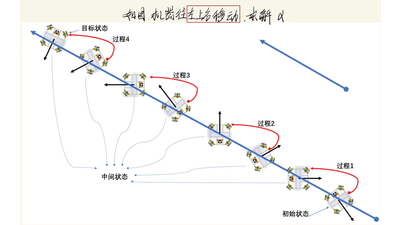
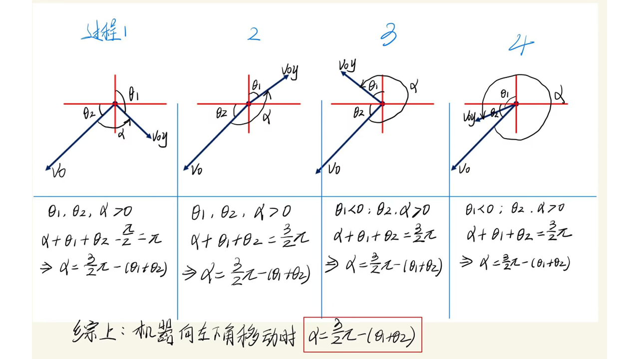
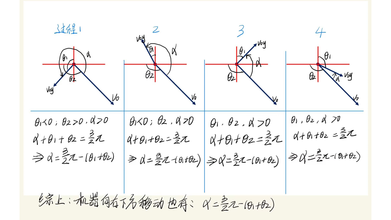
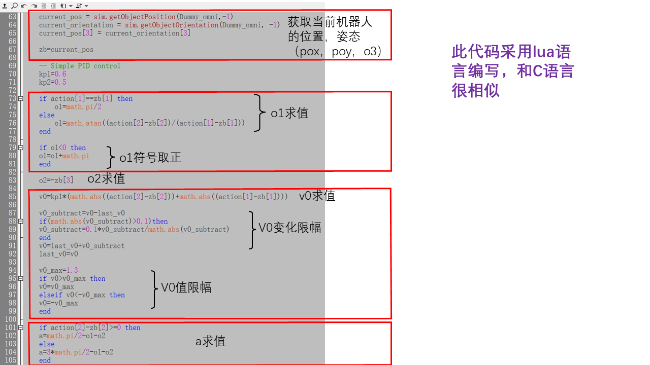
  this what is meant by omnidirectional movement?
  Achieving the above movement is the specialty of the omnidirectional wheel. How is it achieved?


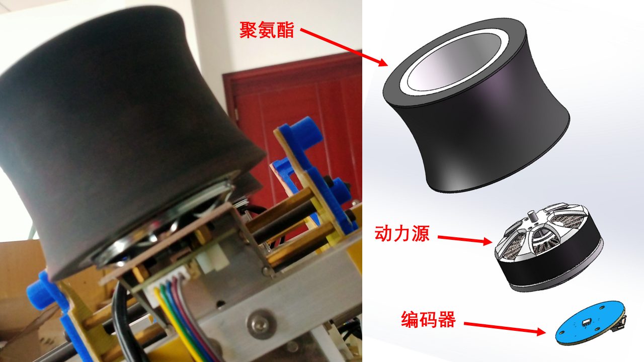
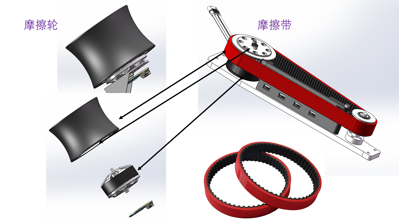
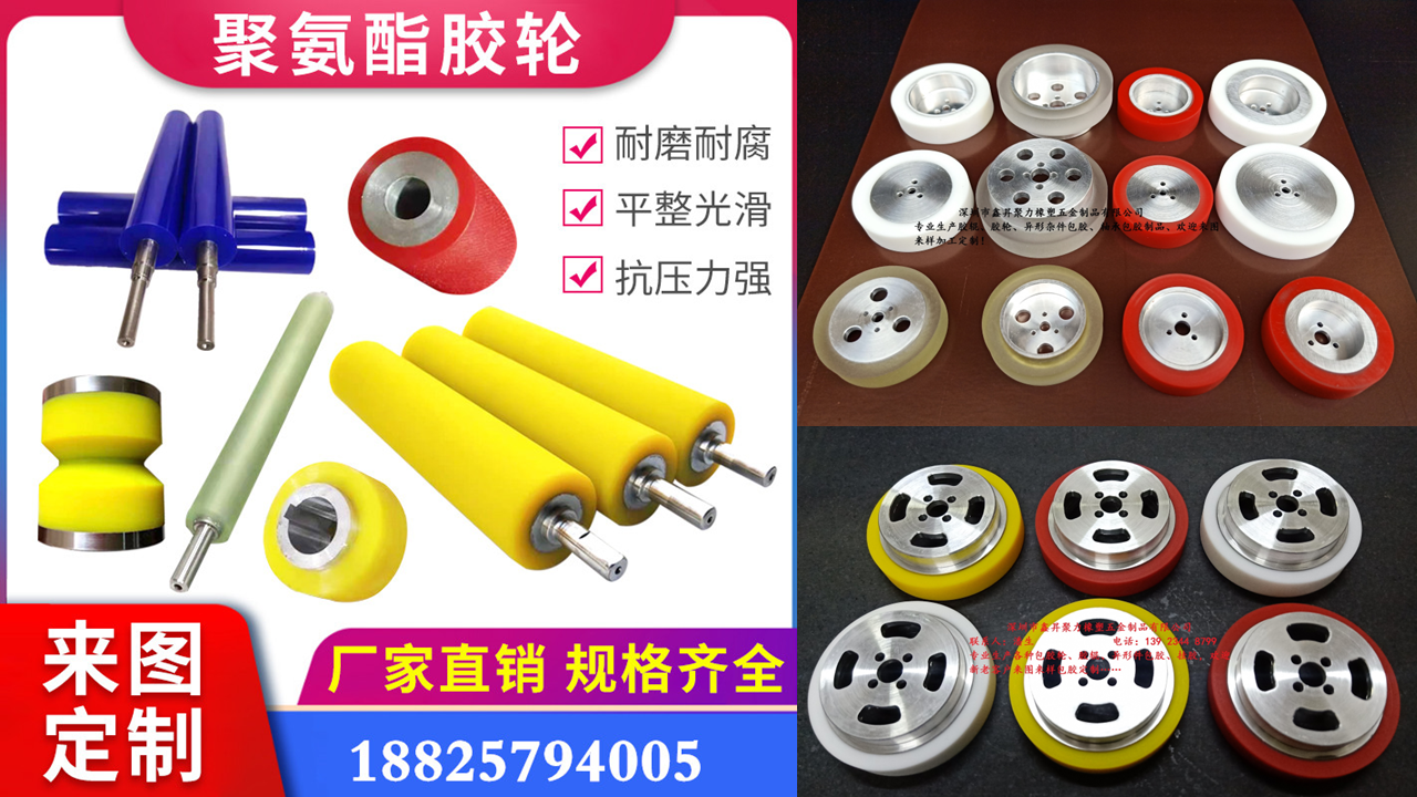 The outer rubber material is polyurethane, which is polymerized from polyester (or polyether) and diisocyanate compounds. It has advantages such as wear resistance, tear resistance, and aging resistance, making it very suitable as a friction wheel for competitions.
 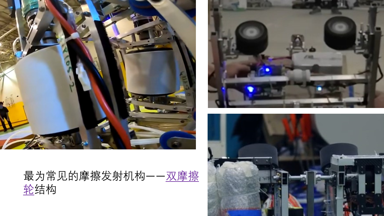 .
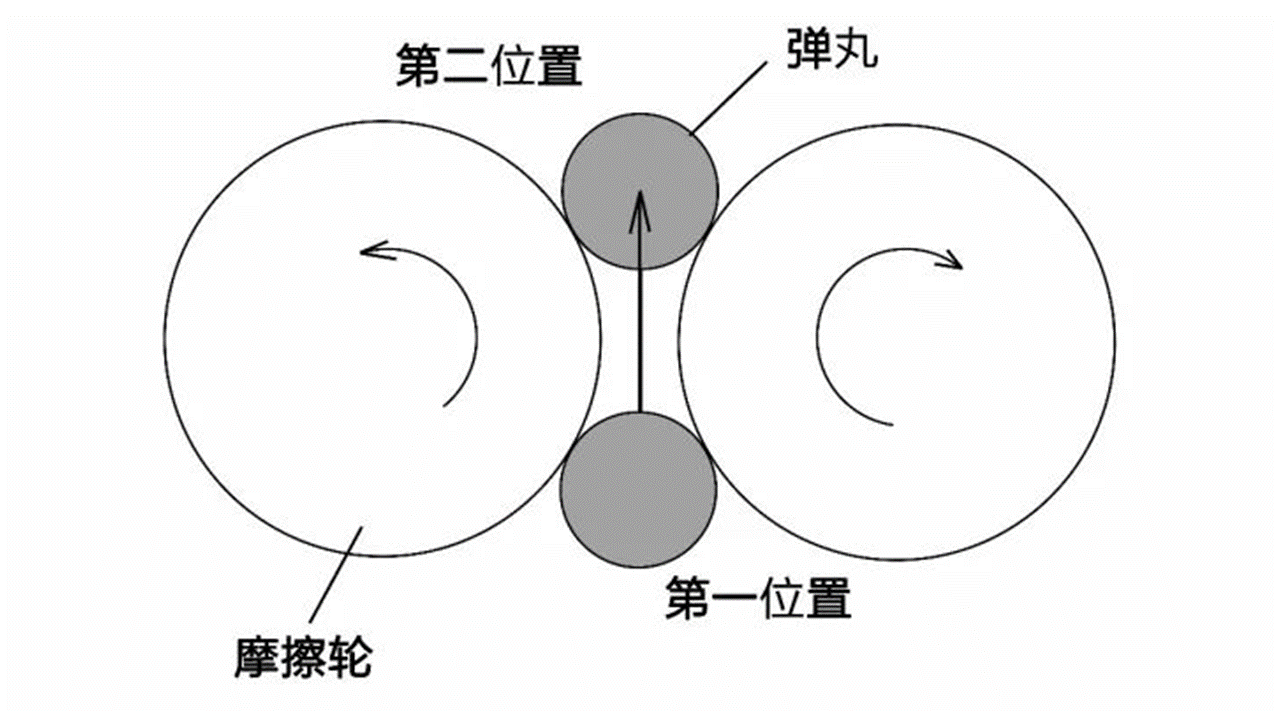
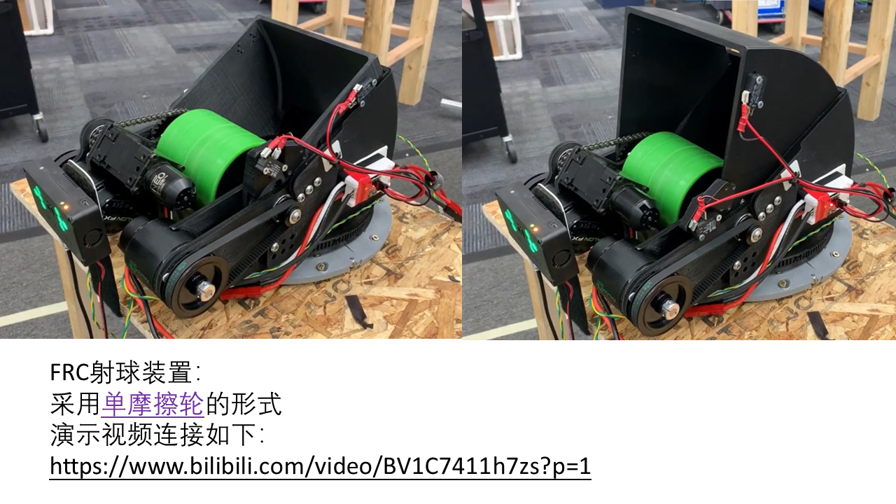
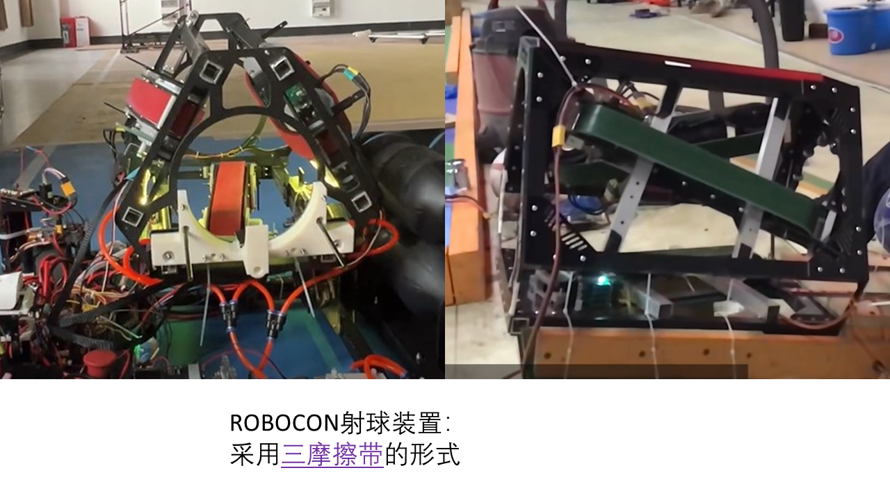
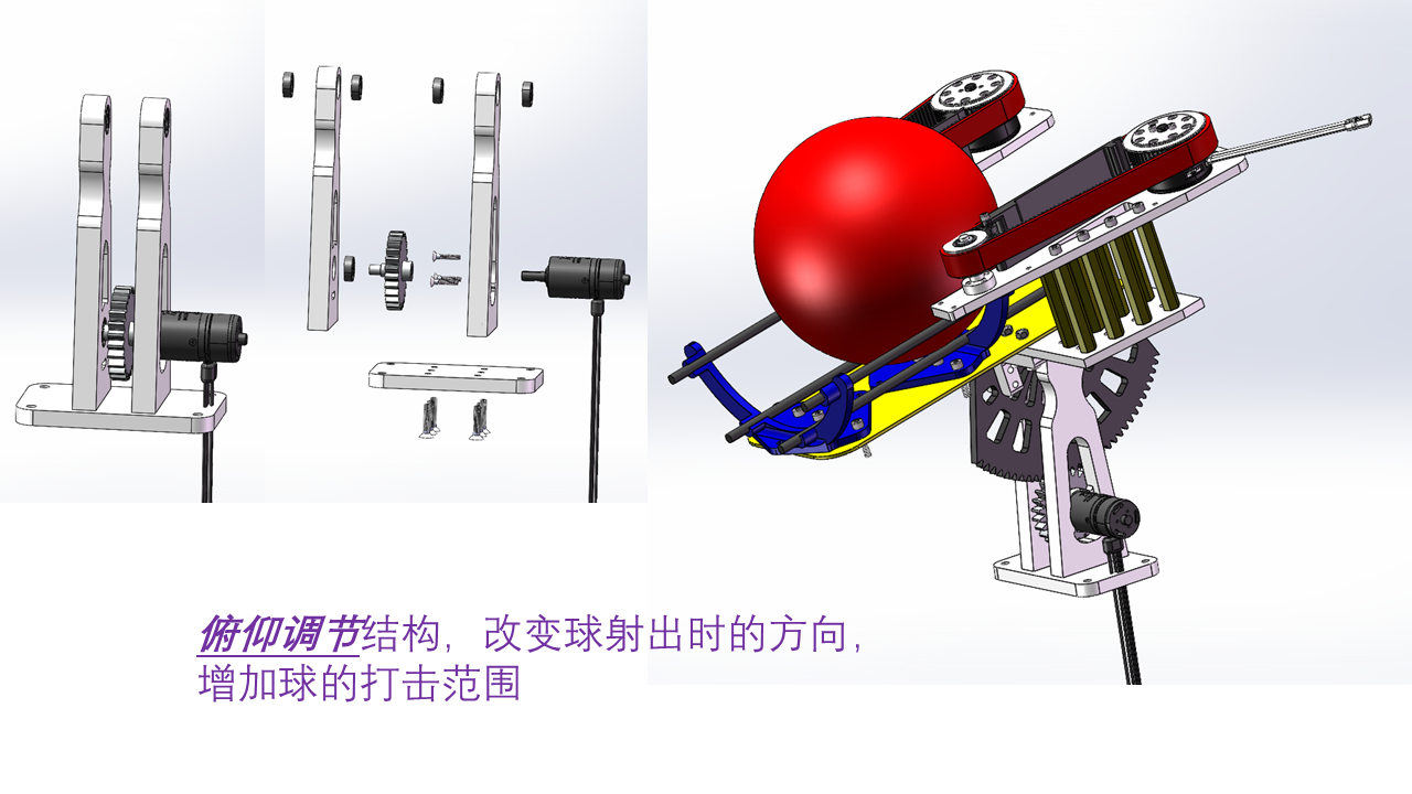
.  . If the friction wheels are too large and the spacing is too small, the first shot will be subjected to a large compressive force to achieve a high rate of fire. However, the reaction force on the friction wheels will also reduce their rotational speed, resulting in a significant decrease in the rate of fire for the second shot. This problem becomes very noticeable when a very high firing rate is required, and is one of the important reasons for the instability of the friction wheel trajectory. The greater the torque and moment of inertia of the motor driving the friction wheel, the smoother the rotation and the more stable the trajectory. However, a stronger motor also means a greater weight. If the firing mechanism is too heavy, it becomes difficult to control it for rapid aiming. Friction wheel electronic speed controllers (ESCs) can detect and control the friction wheel's rotational speed in real time through an encoder and provide feedback. Some ESCs have better internal algorithms and can effectively control the motor speed without feedback. The open-source odrive driver solution can be used: 4.3 Launching Mechanism 2nd Generation ****************************************************************************************************************************************************** To obtain a reliable friction acceleration effect, friction launching has evolved from the initial dual friction wheel to many new structures . Dual friction wheel structure: -------------------------------------------------------------------------------------------------------------------------------------------------------------------------------------------------------------------------- Single friction wheel structure: Although it only has one friction wheel, it has a long friction acceleration section, ensuring the friction acceleration effect! ---------------------------------------------------------------------------------------------------------------------------------------------------------------------------------------------- Four-Friction Wheel Structure: The left image shows a front-to-back arrangement for multi-stage acceleration; the right image shows a circular distribution for omnidirectional acceleration .--------------------------------------------------------------------------------------------------------------------------------------------------------------------------------------------------------------- Three-Friction Belt Structure: The friction belt structure allows the ball sufficient acceleration time .------------------------------------------------------------------------------------------------------------------------------------------------------------------------------------------------------------------------------------------------------------- ----------------------------------------------------------------------------------------------------------------------------------------------------------------------------------------------------------------------------------------------------------------------------- Based on the analysis of the characteristics of the above various friction launch structures, the 'Sun Chaser' Launch Mechanism 2nd Generation was born! It consists of two parts: launch and elevation. ********** ...
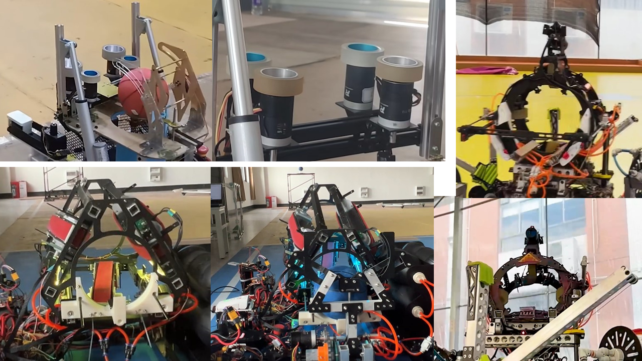


 **************************************************************************************************************************************************************************************************************
  **************************************************************************************************************************************************************************************
  ******************************************************************************************************************************************************************************************

All reference designs on this site are sourced from major semiconductor manufacturers or collected online for learning and research. The copyright belongs to the semiconductor manufacturer or the original author. If you believe that the reference design of this site infringes upon your relevant rights and interests, please send us a rights notice. As a neutral platform service provider, we will take measures to delete the relevant content in accordance with relevant laws after receiving the relevant notice from the rights holder. Please send relevant notifications to email: bbs_service@eeworld.com.cn.
It is your responsibility to test the circuit yourself and determine its suitability for you. EEWorld will not be liable for direct, indirect, special, incidental, consequential or punitive damages arising from any cause or anything connected to any reference design used.
Supported by EEWorld Datasheet
EEWorld
subscription
account

EEWorld
service
account

Automotive
development
community

Robot
development
community

About Us Customer Service Contact Information Datasheet Sitemap LatestNews


Room 1530, 15th Floor, Building B,
No.18 Zhongguancun Street,
Haidian District,
Beijing, Postal Code: 100190
China
Telephone: 008610 8235 0740
 京公网安备 11010802033920号

 2200SG3F004F3FA


