This intelligent air conditioner controller is custom-designed for Midea air conditioners. Utilizing the powerful functions of the ESP32 microcontroller and seamlessly integrated with Apple HomeKit, it allows for easy control of the air conditioner using iOS devices.
This design uses the ESP32 as the core controller, enabling remote control of the air conditioner. Users can connect to the ESP32 via mobile phones, tablets, or other smart devices to operate the air conditioner. The system can control various parameters such as temperature, fan speed, and mode. Users can remotely adjust the indoor temperature and fan speed according to their actual needs, greatly improving the convenience of daily use.
With WiFi connectivity, the ESP32 can connect to the home network, transmitting control signals to the air conditioning system via the internet. Users can operate the air conditioner at home, in the office, or even when away from home through the accompanying application or web interface. This design not only solves the problem of traditional remote controls being easily lost but also enhances the flexibility and intelligence of the device. Users no longer need to operate the air conditioner near it; they can easily control it from anywhere.
This project consists of the following parts: automatic download circuit, main control unit, infrared transmitter, etc. This project mainly uses the ESP32 to control the infrared transmitter to emit air conditioner control infrared codes. The OLED part can be ignored.
A TYPE-C-16P interface is used as the power supply interface. The corresponding USB data pins are connected to the corresponding USB pins on the S3 (USBD+ IO20), (USBD- IO19). USB is used directly for downloading and debugging, without needing to convert to serial signals. 5.1K pull-down resistors are added to the CC1 and CC2 pins for easy identification and configuration by different hosts.
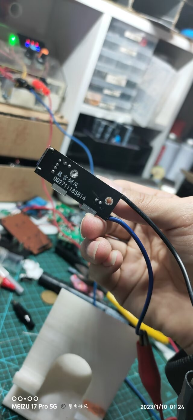
Please note that currently only the HP CSPS 750W can be started with this solution
(because I don't have other CSPSs at the moment) .
High power consumption has not been tested
(this is my first time designing a PCB).
This project is very simple, but my soldering skills are not good.
I am in my dormitory and only have a low-power soldering iron
. However, theoretically, a PCB is not needed. You only need to ground the HP power supply from the right and connect the 4th pin to the bottom to power on.
However, I do not want to "damage" the power supply
because this power supply was taken from a server and may be reinstalled and used.
Therefore, I made this PCB
product demonstration:

(Not important, server picture)

PDF_Simple HP CSPS Power Adapter.zip
Altium_Easy HP CSPS Power Adapter.zip
PADS_Easy HP CSPS Power Adapter.zip
BOM_Simple HP CSPS Power Adapter.xlsx
92285
Smart curtains based on the [LCSC Liangshanpai Development Board]
The Liangshan School-based smart curtain system is a smart home device that integrates voice control, infrared remote control, and automatic mode. The system can automatically open and close the curtains based on environmental conditions such as light intensity and raindrop detection, while also supporting manual control by the user via voice commands or an infrared remote control.
1. Background
With the development of science and technology and the improvement of people's living standards, intelligent home systems are increasingly appearing in people's lives, bringing people a fast and comfortable experience. For home necessities, curtains occupy an important position. Since manual curtains need to be opened and closed manually, electric curtains cannot be automatically controlled according to the light intensity and require a specific remote control, which has certain limitations. Therefore, an intelligent curtain control system based on Liangshanpai microcontroller was designed.
2. Technical indicators
(1) Automatic mode can be set to open or close via infrared remote control and voice; (2) In automatic mode, the curtains will automatically open when the light intensity is high and automatically close when the light intensity is low; (3) In automatic mode, the curtains will automatically open when a large number of raindrops are detected, which has a higher priority than light detection; (4) The curtains can be opened and closed at any time via infrared remote control or voice command, and the automatic mode can be closed; (5) After receiving the data, the main control chip drives the motor to run, realizing the intelligent curtain window system.
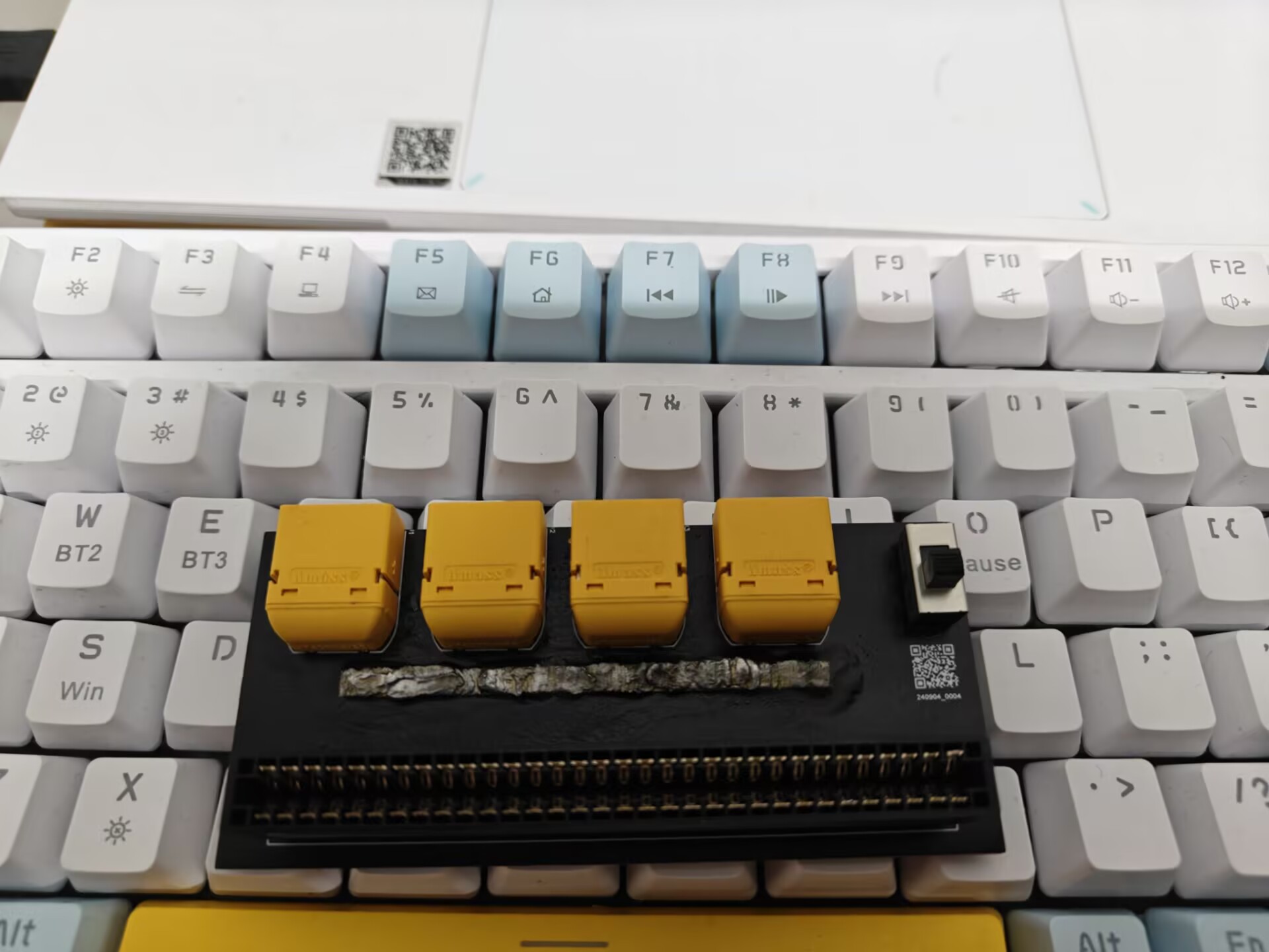
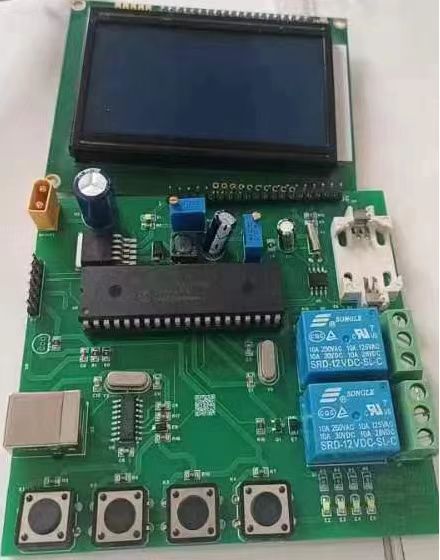
3. Main control
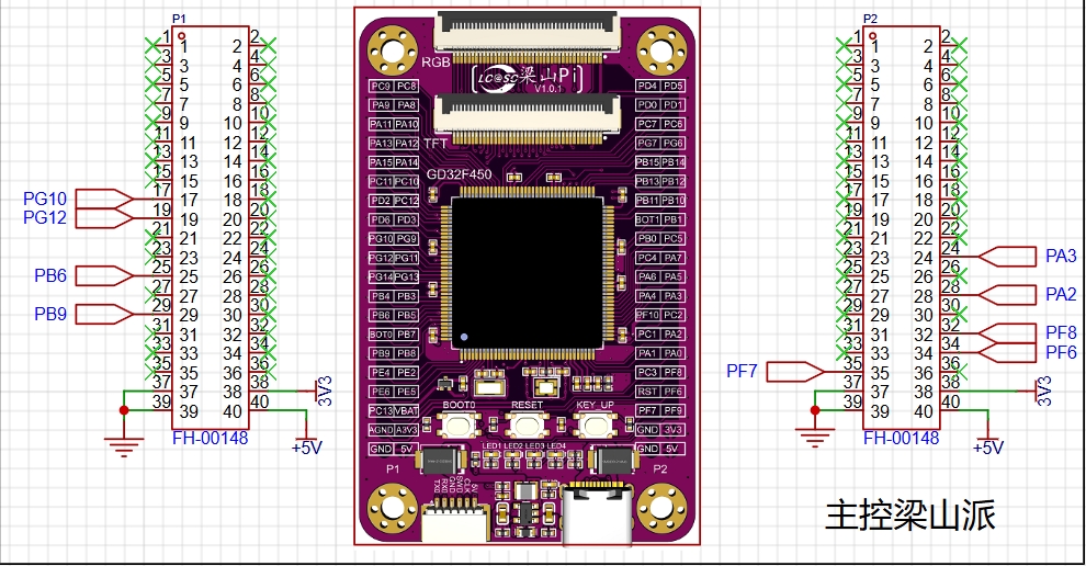
This expansion board uses Liangshanpai development board as the main control and brings out the pins to be used.
4. Raindrop and Light Detection
: Raindrop detection: The common working principle of raindrop sensors is to determine whether it is raining by detecting the conductivity of water droplets. It uses the change in conductivity between two electrodes to measure the presence of water droplets. There is an air gap between these two electrodes, which is normally an open circuit. When a water droplet comes into contact with the electrodes, the conductivity of the water droplet causes current to flow through the droplet, forming a current loop, thereby changing the resistance value between the electrodes. By measuring the change in resistance value, the presence of water droplets can be determined.
Light Detection: The light detection function of the expansion board is identified through a photoresistor. A photoresistor is a special resistor whose resistance value decreases rapidly with the increase of light intensity. In the absence of light, it is almost in a high-resistance state, so the resistance is very high in the dark.


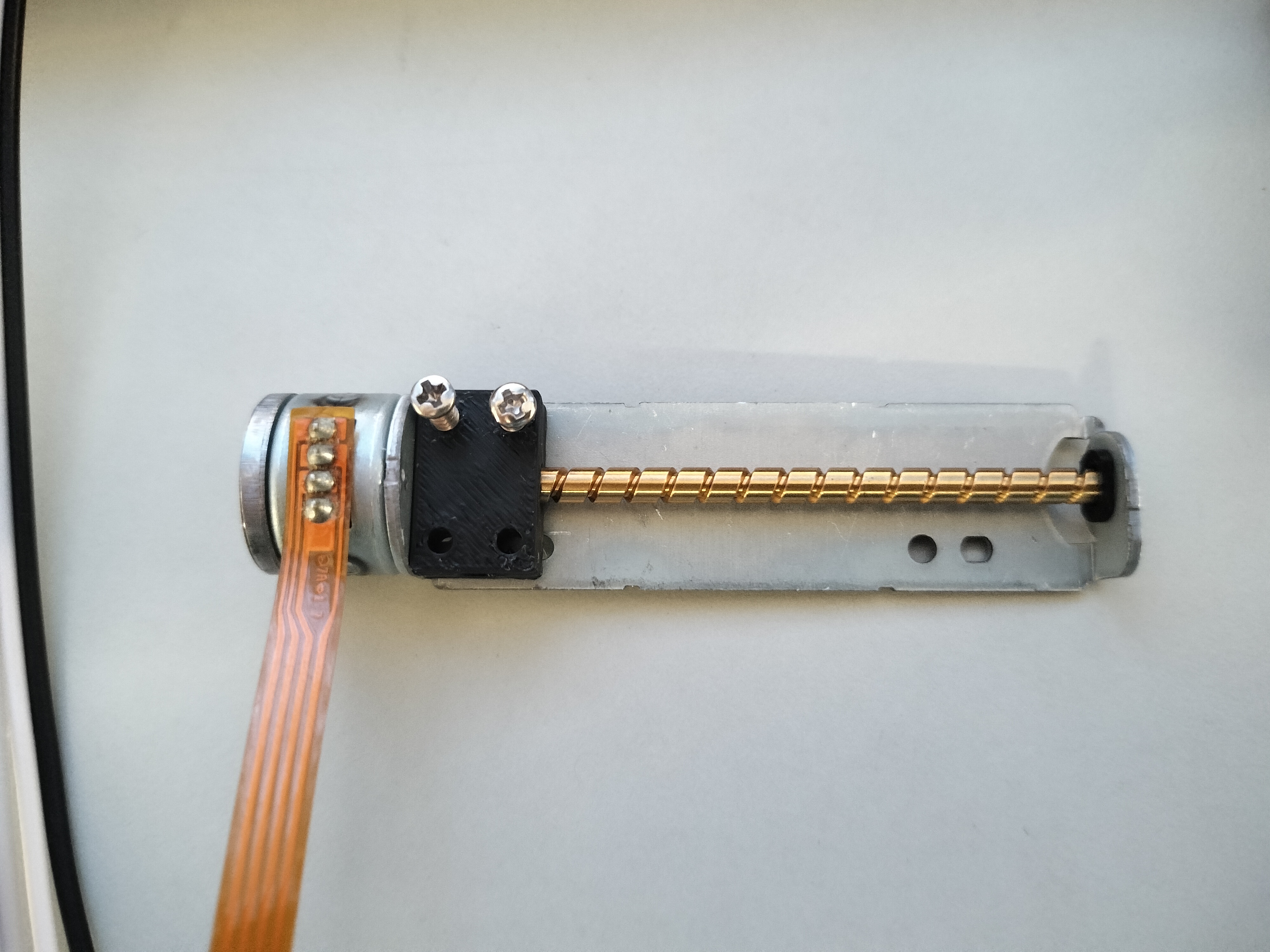
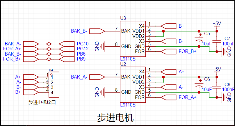
5. Two-Phase Four-Wire Stepper Motor:
A two-phase four-wire stepper motor is a common type of stepper motor. Its principle is based on electromagnetic induction and electromagnetic attraction. It has two stator coils (referred to as phase A and phase B respectively) and a rotor (also called the shaft of the stepper motor). When phase A coil is energized, it generates a magnetic field. According to the right-hand rule, this magnetic field causes the rotor to rotate in a specific direction. Similarly, when phase B coil is energized, it also generates a magnetic field, causing the rotor to rotate in the opposite direction. By changing the direction and magnitude of the current in phase A and phase B coils, the number of steps and direction of rotation of the stepper motor can be controlled.
Specific schematic diagram shown:
6. Infrared
Remote Control Infrared Receiving Principle: The principle of infrared receiving is to utilize infrared radiation illuminating the infrared receiver head. A weak electrical signal is generated by the infrared photosensitive device, and after amplification and processing by the circuit, the infrared signal can be identified and decoded. Infrared Protocol Introduction: In the spectrum, electromagnetic waves with wavelengths from 760nm to 400um are called infrared rays, which are invisible light. We are all familiar with examples of infrared communication. Currently, almost all commonly used household appliances can be controlled via infrared remote control, such as televisions, air conditioners, and projectors. This technology is widely used, and the corresponding components are very inexpensive, making infrared remote control an ideal method for controlling our daily equipment.
7. HLK-V20 Voice Module
: The HLK-V20 is a high-performance, purely offline voice recognition module launched by Hailink Electronics for numerous purely offline control scenarios and products. It can be widely and quickly applied to smart homes, various smart small appliances, 86-type set-top boxes, toys, lighting fixtures, industrial applications, medical devices, IoT devices, automobiles, security and lighting, and other products requiring voice control. The HLK-V20 supports offline recognition of 150 local commands, allows for free customization of wake-up words, command words, and response broadcast words, and has rich peripheral interfaces. Offline voice recognition means it can only recognize fixed command words and does not require a network connection.
Specific schematic diagram:
This voice recognition module allows us to freely design command words, which can be configured through an online configuration platform. After configuration, a voice recognition firmware will be generated. We need to download the firmware to the module through pins B6 and B7. Therefore, pins B6 and B7 are brought out via headers below for easy downloading. It is also important to note that the module must be powered off before downloading the firmware. Power should only be applied to the module after the download tool has recognized it for normal downloading. This power-on/off operation is controlled by switch SW1 in the schematic diagram.

During the debugging process
, the voice firmware could not be burned
. First attempt: Unable to burn normally; after testing, it was found that the USB to TTL adapter was incompatible. Solution: Purchase a CH340 programmer.
Second attempt: During burning, it continuously displayed "device is waiting," and it was found that the DuPont wire had poor contact. Solution: Replace the DuPont wire.
code.zip
WeChat_20240912121628.mp4
PDF_Smart Curtain Based on [LCSC Liangshanpai Development Board].zip
Altium-based Smart Curtain (based on LCSC Liangshanpai Development Board).zip
PADS_Smart Curtain Based on [LCSC Liangshanpai Development Board].zip
BOM_Based on the [LCSC Liangshanpai Development Board] Smart Curtain.xlsx
92286
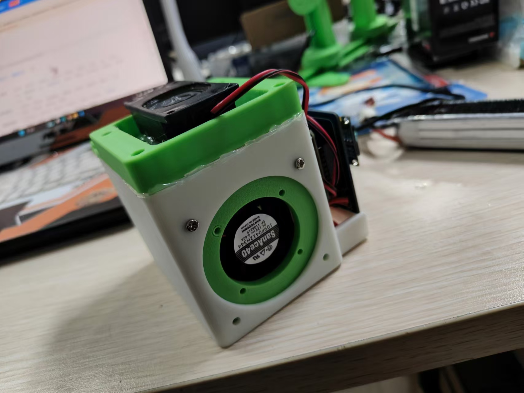
Multifunctional welding filter fan
A multi-functional desktop exhaust fan that can be voice-controlled; some functions are still being improved.
A simple, voice-controlled, multi-functional desktop exhaust fan.
The design was inspired by the heavy welding fumes in the lab; seeing this event prompted the creation of this small exhaust fan.
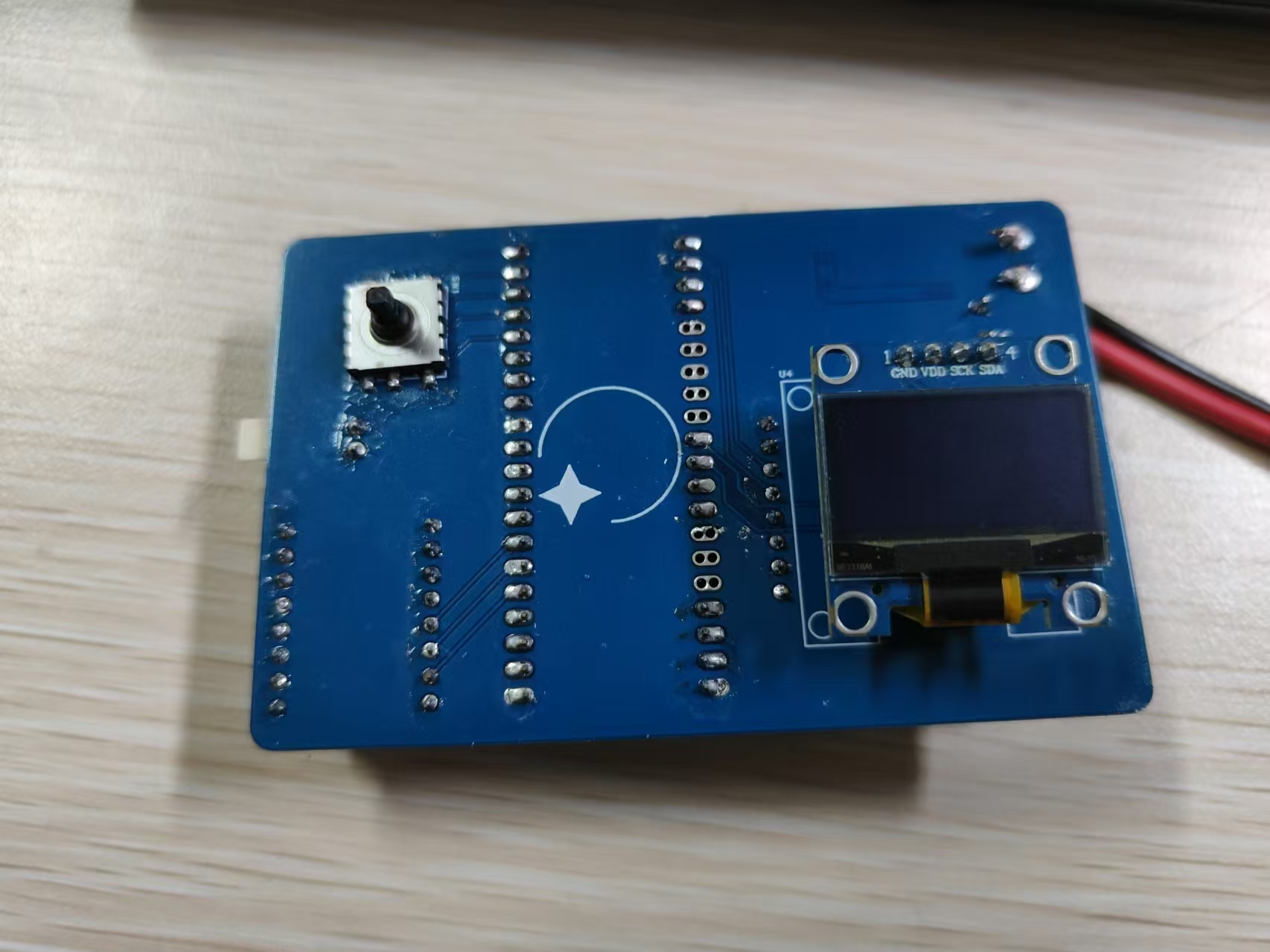
To reduce costs, I used readily available modules and a LCSC ESP32 development board. The voice module and ESP32 communicate via serial port for bidirectional control. Other functions can also be achieved using the OLED and five-way switch on the back.
Currently implemented functions include: multi-level fan speed control and voice control.
Upcoming functions include: OLED weather forecast and clock, and Bluetooth control.
The complete product is shown in the image.
Note: The voice module must be removed and programmed; otherwise, it will not be detected.
A demo video is attached.
8584155a112cdcdd4a67ba1bd516259d.mp4
PDF_Multifunctional Welding Filter Fan.zip
Altium_Multi-functional Welding Filter Fan.zip
PADS_Multifunctional Welding Filter Fan.zip
PDF_Multifunctional Welding Filter Fan.zip
Altium_Multi-functional Welding Filter Fan.zip
PADS_Multifunctional Welding Filter Fan.zip
92287
Roselia_PCB_Light
Roselia Live Tour Rosenchor Shanghai Additional Performance Commemorative Light Board
It is recommended to choose a thinner board thickness, otherwise the yellow substrate will significantly affect light transmission.
Immersion gold plating with black solder mask is suggested.
The actual effect of Kirakira is shown in the image below (thickness 1.6).


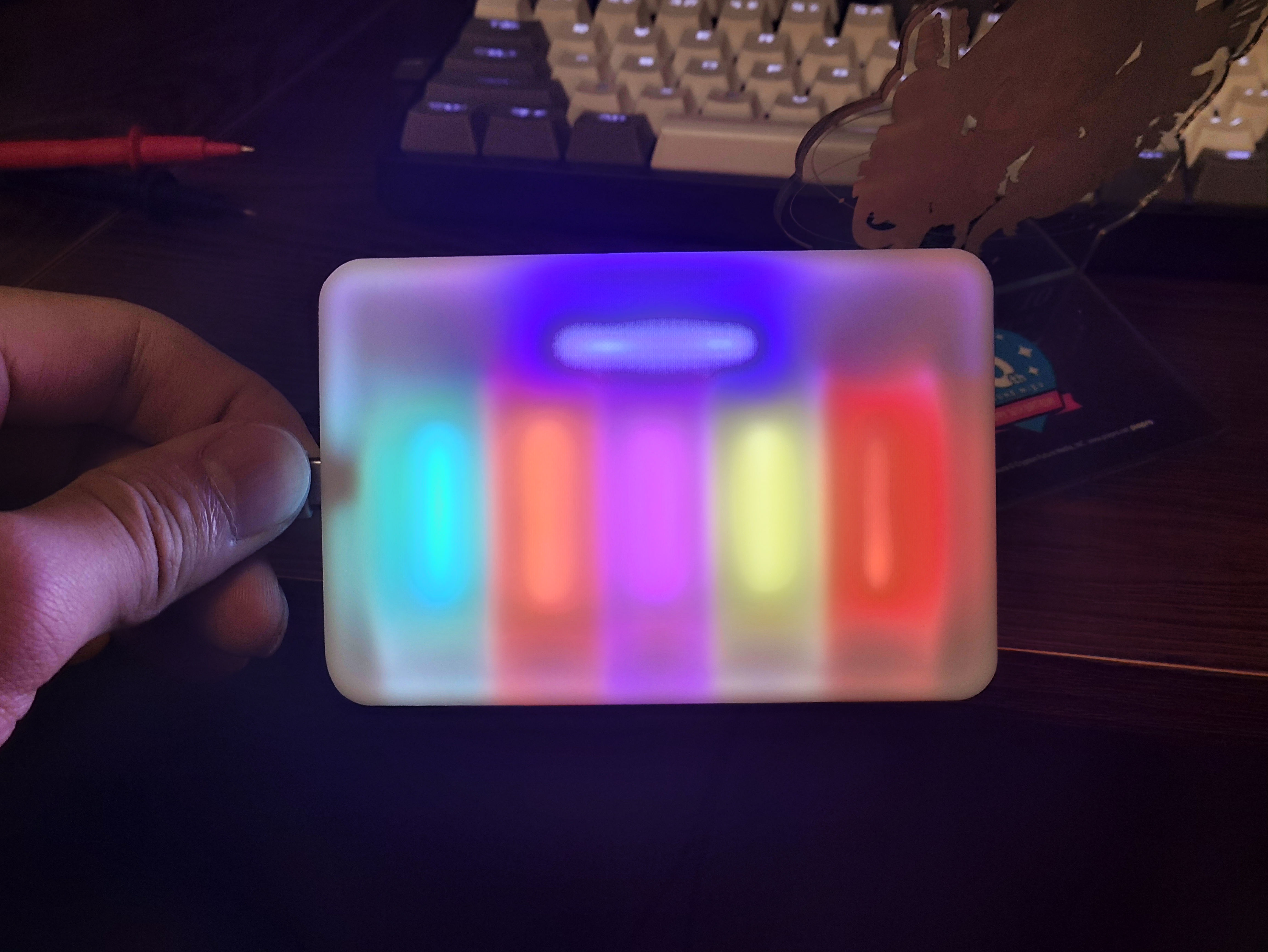
Lightroom color adjustment can slightly improve this, as shown in the image below. The

back uses 38mm-40mm LED flexible filaments (red, white, purple, pink, ice blue, blue).
The casing is made using JLCPCB 3D printing.
Accessories include the casing and Gerber (Roselia_PCB_Light.zip). If you don't want to modify it, you can directly order the Gerber.
Note:
1. The original USB female connector had two positioning holes, which were removed to ensure a neat appearance. Therefore, the positioning pins under the female connector must be scraped off during soldering.
2. When soldering the filament, it is recommended not to let the filament be tightly attached to the board. Utilizing the reflection from the casing can make the light transmission more even.
3. The bottom of the board is silkscreened with "jlcjlcjlc". You can choose to add a custom code at a specified location when ordering.
Roselia light panel housing.zip
Roselia_PCB_Light.zip
PDF_Roselia_PCB_Light.zip
Altium_Roselia_PCB_Light.zip
PADS_Roselia_PCB_Light.zip
BOM_Roselia_PCB_Light.xlsx
92289
STM32F103C8T6 Minimum System Board Design
For this first attempt by a beginner, I added a CH340 module and a matching USB-Type-C interface according to my personal habits for easy debugging, and used the simple horn-shaped connector used by ST-linkV2 as the download interface to avoid the trouble of matching the interface when connecting DuPont wires.
MCU chip: STM32F103C8T6;
Serial port chip: CH340N;
Operating voltage: 5V|3.3V;
Attachment: Keil5 test project, including PC13 LED and USART1 initialization.
STM32F1_TEST_PROECT.zip
PDF_STM32F103C8T6 Minimum System Board Design.zip
Altium_STM32F103C8T6 Minimum System Board Design.zip
PADS_STM32F103C8T6 Minimum System Board Design.zip
BOM_STM32F103C8T6 Minimum System Board Design.xlsx
92290
ESP32's voice assistant
ESP32-based voice assistant
Project Overview:
This project is a voice assistant based on the ESP32 microcontroller. It features speech recognition and can answer simple questions.
Project Functionality:
This design is based on the ESP32-S3. It recognizes the input speech as text, connects to a big data model to obtain the answer, and then regenerates the text into speech for feedback.
Project Principle:
The main control chip used is the ESP32-S3-WROOM, which supports multiple communication protocols and can connect to Wi-Fi, Bluetooth, and Zigbee to meet different wireless communication needs.
The voice module uses the INMP441, which sends the PCM audio input from the i2s microphone to the SST speech recognition service to convert it into text. The obtained text answer is then converted back into speech via TTS for playback (the "speech-to-text-to-speech" process uses the iFlytek API).
The language model used is Volcano Engine (https://www.volcengine.com/product/ark)
, which is relatively easy to configure and suitable for beginners. WebSocket connections are used to process audio data, enabling streaming transmission and ensuring dialogue continuity.
The interactive components consist of two parts: a 1.8-inch touchscreen display and a MAX98357A audio power amplifier for voice playback and human-computer interaction.
The software
code references the large language model AI voice assistant from the Bilibili blogger "Bao Gai Chef Zhang Zuoren".
Important note:
Because the speech-to-text conversion and language model are from different websites, keyword fields in the code should be modified to ensure correct API connection.
The Wi-Fi name and password should be configured in advance in the code.
[Image of the actual product]

PDF_ESP32's Voice Assistant.zip
Altium_ESP32's Voice Assistant.zip
PADS_ESP32 Voice Assistant.zip
BOM_ESP32's Voice Assistant.xlsx
92291
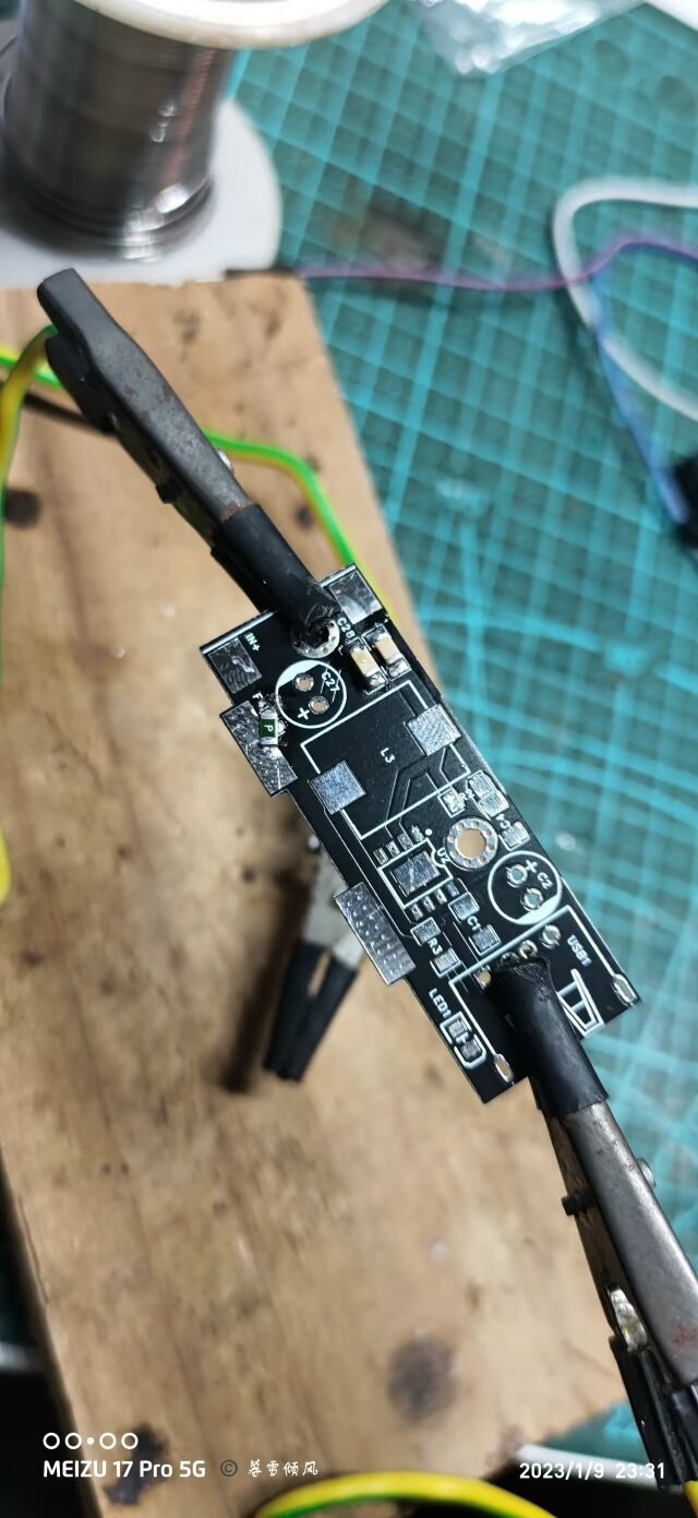
IP6505T-USB Fast Charging Module (Expandable)
This is a USB fast charging module based on the IP6505 chip. My tests show that with sufficient power, it can support a maximum output of 22W.

Test Results.mp4
PDF_IP6505T-USB Fast Charging Module (Expandable).zip
Altium IP6505T USB Fast Charging Module (Expandable).zip
PADS_IP6505T-USB Fast Charging Module (Expandable).zip
BOM_IP6505T-USB Fast Charging Module (Expandable).xlsx
92293
IoT Voice Clock
A simple IoT clock

The ability to obtain time via the internet
is a feature currently under development.
PDF_IoT Voice Clock.zip
Altium_IoT Voice Clock.zip
PADS_IoT Voice Clock.zip
BOM_IoT Voice Clock.xlsx
92294
electronic
 Example Figure 1 -- Power Circuit:


 京公网安备 11010802033920号

 26G-8
26G-8


