This is a main control board similar to Tmall Genie, implemented using the ESP32S3. Currently, it's built using a modular assembly method. The main control board uses an ESP32S3 development board inserted into the verification board. Voice, amplifier, and SD card also use readily available modules, mainly saving time on hardware verification and directly verifying the software implementation. After stable verification, we plan to integrate them onto a single board later. The main functions implemented so far are as follows: 1. Human-computer dialogue based on a large language model. Press and hold the OK button, then speak. Releasing the button converts the speech to text, then requests a request from the backend to relay it to a third-party large language model. The returned text content is sent to the device, which then converts the text back to speech and plays it through the amplifier. Currently, it's integrated with Baidu Wenxin Yiyan for verification. Compared to GPT, Wenxin Yiyan is significantly inferior, but GPT has limited use in China and presents many problems. However, more other models, such as Microsoft Azure, will be integrated later. The integration model is configured in the backend, and model switching is transparent to the device. 2. Smart switch. The smart switch is the origin of my design for this board. Currently, it works with two other 8266 main control relay boards (one 86-in-one board and one micro single-control board, which will be open-sourced simultaneously) to achieve voice and infrared remote control of light on/off. During the initial configuration phase, an internet connection is required to configure the device. After the device is configured, all commands will be cached on the main control board, and then it can control other devices offline. 3. A touch screen will be added later to achieve more functions. 4. The ultimate goal is to achieve complete backend programming of the device using a server-side language like Java.
Soldering:
1. Two ESP32S3 development boards are configured on the board to support insertion on both the top and bottom of the board. Only one board needs to be inserted on one side, and the pins of both are the same.

2. The resistor values configured for the 5 buttons must be soldered according to the values in the schematic diagram. Otherwise, the analog signals read by the program will have problems, and the buttons may malfunction or become disordered.

Flashing and Networking:
Assuming you already have a main control board and all related accessories and modules are properly soldered. The usage method is as follows:
1. First, connect the board to the computer using a USB cable. Flash the attached jmicro_v3.0.1_all.bin to address 0x0. If you have an IDF environment, you can execute the following command:
`esptool.py -p COM19 -b 460800 write_flash 0x0 jmicro_v3_all.bin`
. Alternatively, you can use the official firmware flashing tool.
2. After flashing the firmware, connect to the serial port to view the boot log. Currently, this firmware has complete log output, so there is some performance loss. Upon initial startup,
it will automatically enter Wi-Fi pairing mode. Check the Wi-Fi list on your phone or computer to see if the ESP32_CFG Wi-Fi is listed. If not, manually and quickly press
the Left button on the board three times. Wait a moment and check again; you should now see the board's open hotspot, as shown in the image below.

3. After connecting to this Wi-Fi, open http://192.168.4.2 in your browser.

On the page shown below, enter your home Wi-Fi username and password, click submit, and after seeing "success," the board will automatically restart and connect to Wi-Fi. If the Wi-Fi input is incorrect, the board
will fail to connect to Wi-Fi. In this case, you can manually press the Left button on the board three times quickly to reconnect to the hotspot opened by the board until successful.
4. After the board is successfully connected to the network, you need to install the APP to configure the board.
Configure GPIO through the APP
: 1. First, install the attached JMicro.apk on your Android phone (currently only supports Android). At present, the mobile APP is only used as an auxiliary tool for device configuration management (free, ad-free, completely free, please use with confidence);
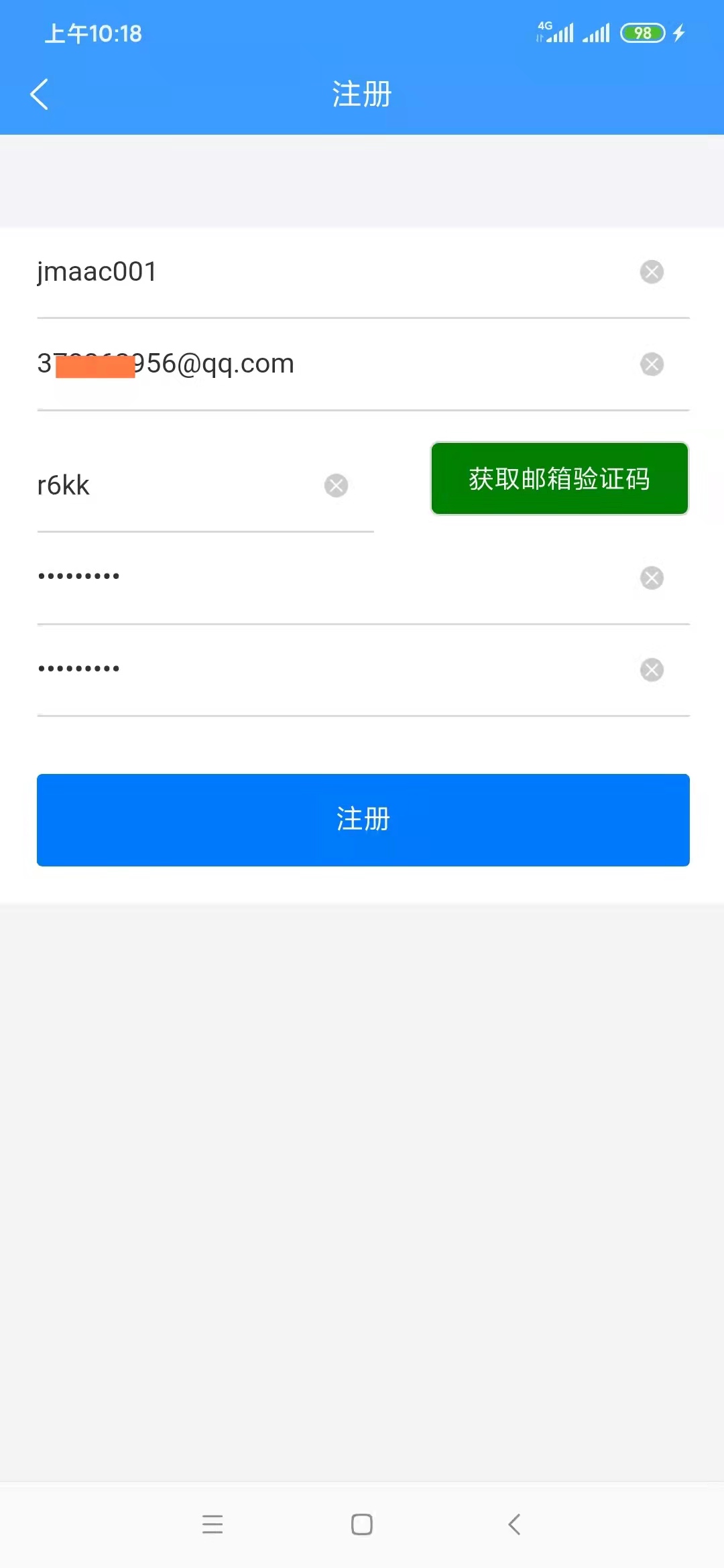
2. Open the APP. The first time you open it, you will be redirected to the login page. If you do not have an account, click "Register Account" to enter the registration page. It should be noted that registration requires an email account to receive a verification code. First, enter a valid email address, such as 3333333@qq.com. It is recommended to use a QQ email or a domestic email address. For reasons we all know, foreign email addresses may not receive the email, or even if received, may not be able to open it.
As for why we don't use a mobile phone number for registration, it's to save costs. A text message costs 1 cent, which is really unaffordable. Please understand. On the other hand, some users are sensitive about mobile phone numbers and are unwilling to give them out casually.
3. After successful registration for the first time, you will be redirected to the login page to log in to the app. You will be automatically logged in afterward unless you uninstall the app. After successful login, you will be automatically redirected to the device configuration homepage.

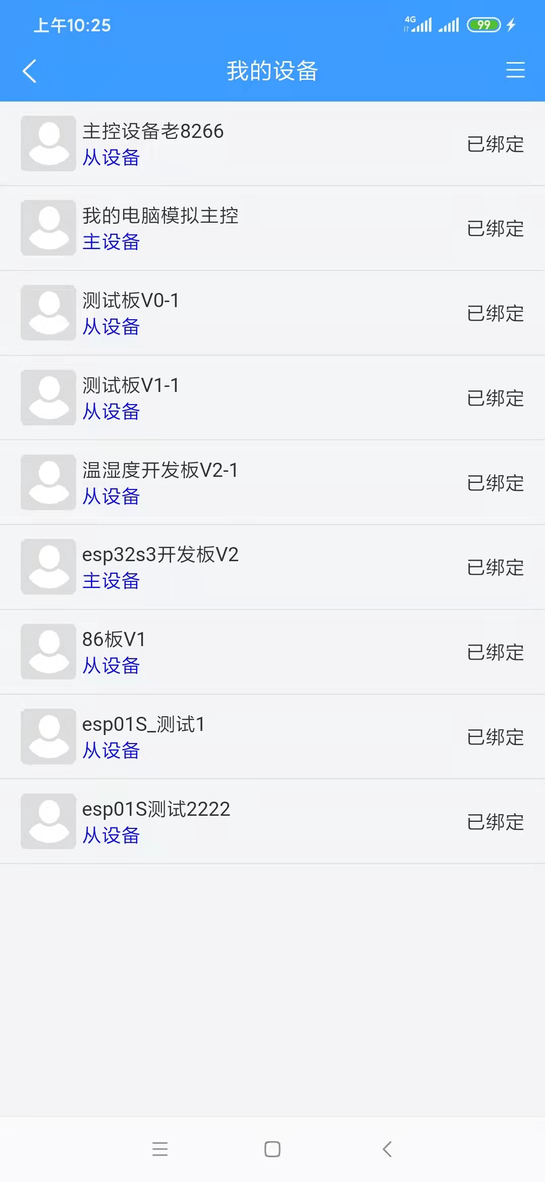
5. To add a device, select "My Devices" to access the device list, as shown below:
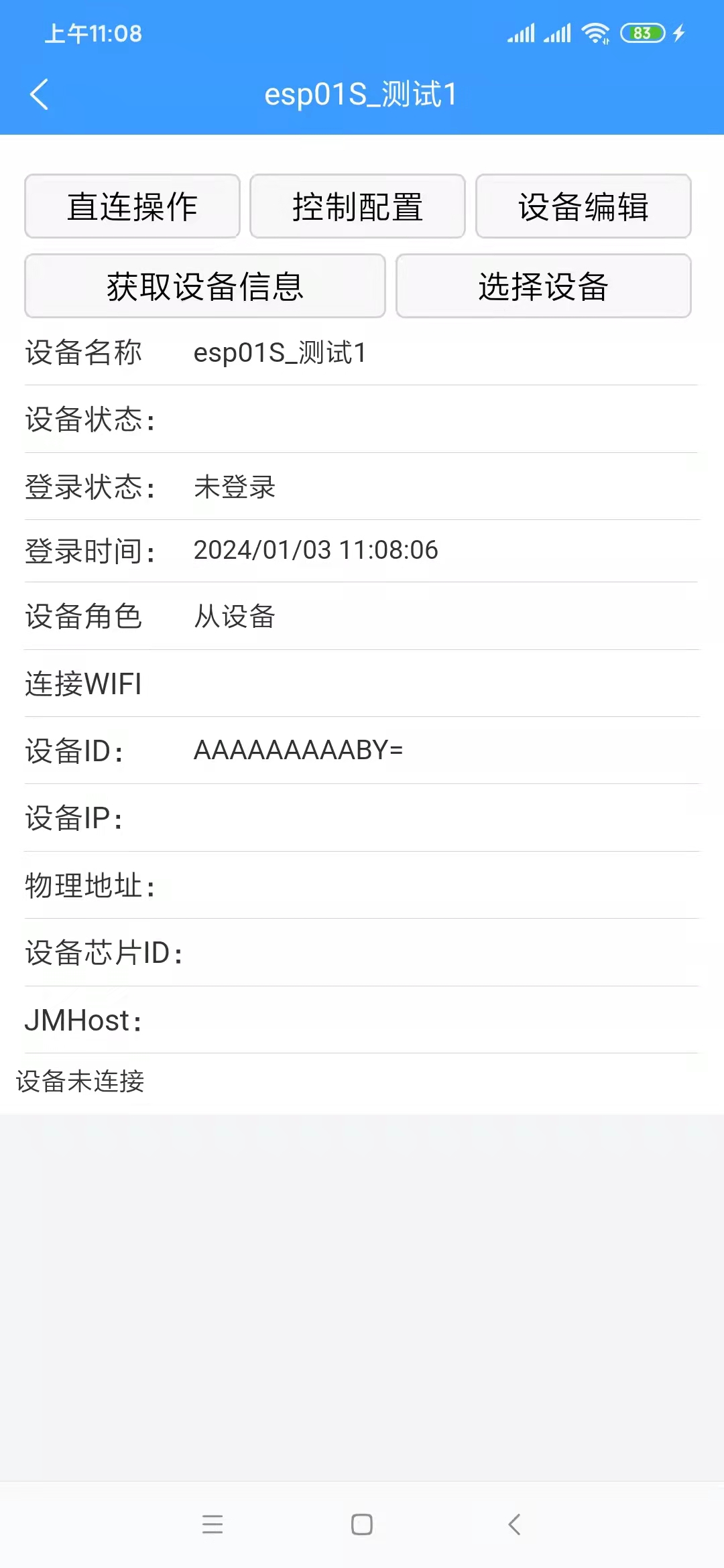
6. To bind a device, ensure that the device is successfully network-configured and that your phone and device are connected to the same Wi-Fi network (this is necessary; otherwise, the app will not be able to find the device). On the page shown above, click "Select Device" to access the device selection page, as shown below.
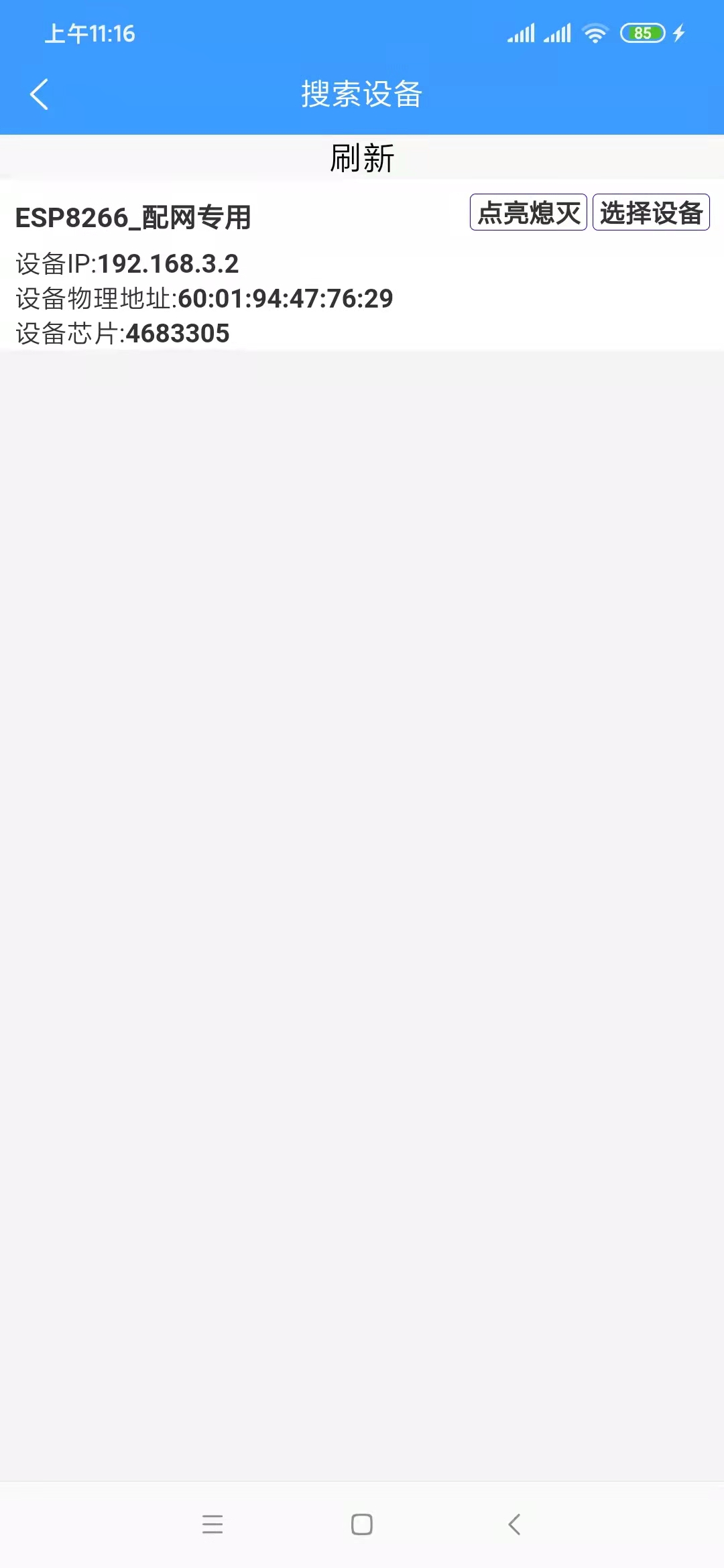
If multiple devices are not yet network-configured and are powered on, this list will display multiple available devices. If there are multiple devices but you are unsure which one is which, click "On/Off" in the list. The device's onboard LED will flash on and off. Clicking "On/Off" again will stop the LED from flashing. Clicking "Select Device" will return you to the device details page, which will display more device information. A "Confirm Binding" button has been added to the button bar. Clicking this button will successfully bind the device.
7. Device roles: Currently, there are three device roles:
Independent Device: This device can exist independently and is not controlled by other devices. It is suitable for scenarios requiring individual control, or scenarios where there is no master device yet and you want to test this device independently.
Master Device: Similar to Tmall Genie, this is the ESP32S3 board. You can control other slave devices through this board. Slave
Device: Similar to an independent device, but it can be added to a master device and controlled by the master device. For example, for devices based on the ESP8266 that are not configured for voice input but still require voice control, this device can be set as a slave device and added to the master device. The master device receives voice control commands to control this device. The attached video shows two ESP8266-based boards, both of which can be used as slave devices.
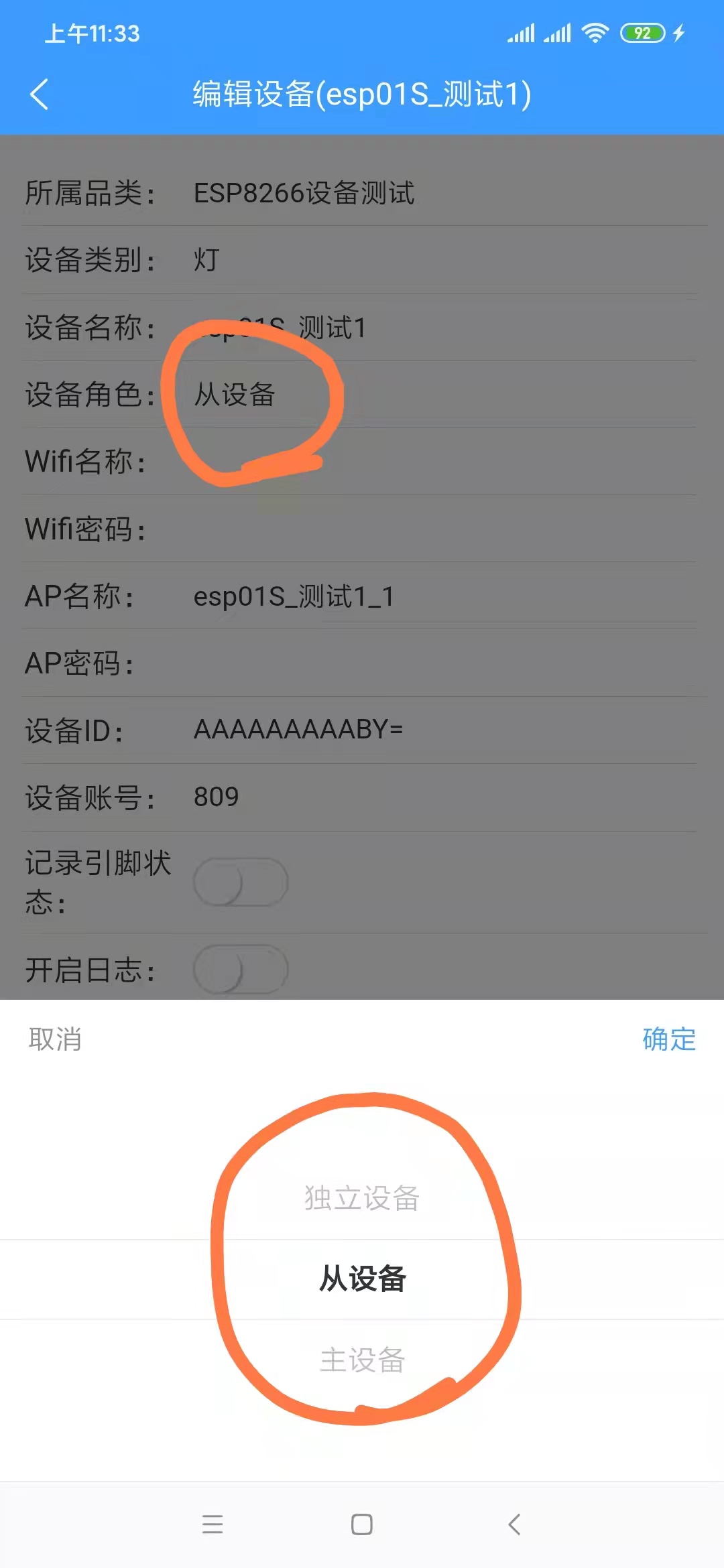
Generally, the ESP32S3 board is set as the master device, and other devices are set as slave devices. Of course, they can also all be set as independent devices, in which case there is no relationship between the devices.
8. After successful device
binding, a "Control Configuration" option will appear on the device details page (see image below). Initially, this list is empty.
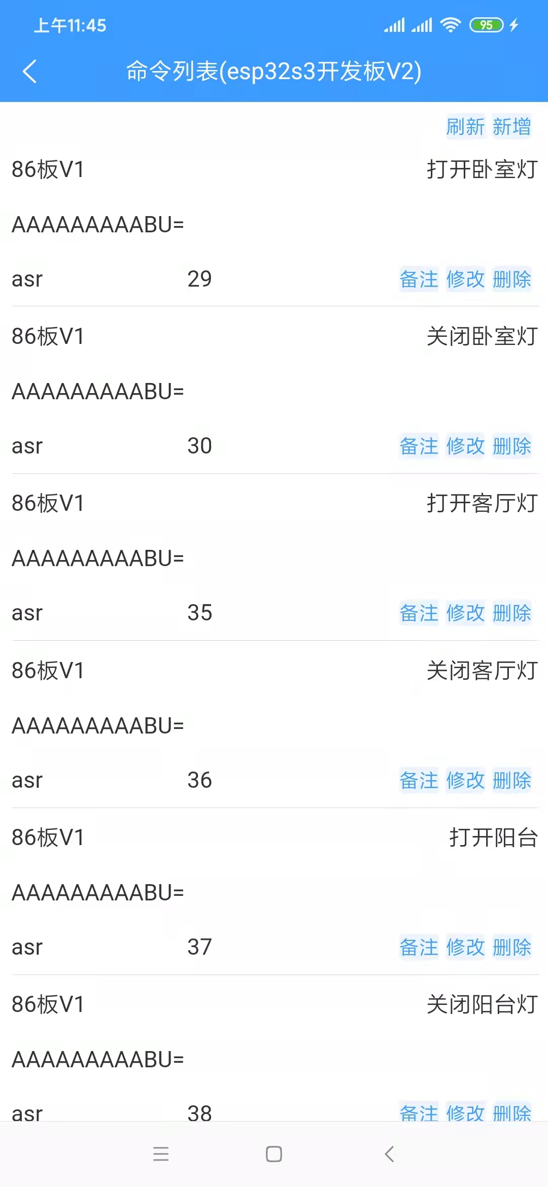
The Chinese text displayed in the upper right corner of each row is the command term. Speaking this command term to the ESP32S3 board will execute the command.
In the upper right corner of the list, there is a "Add" label. Clicking it will take you to the command addition page, as shown below.

Since we are adding a command under the master device, select the slave device to control, provided you already have a slave device.
The command name is the voice command term; the number of characters should be appropriate, preferably between 3 and 8 characters.
The command pinyin does not need to be filled in; it will be automatically generated after successful saving.
The command description is optional.
Select "Voice Command" for the command source; the other option is "Infrared Remote Control."
The command ID does not need to be filled in; the system will create it automatically.
Select "GPIO Control" for the command function.
Execution Instructions: This refers to the voltage level of the microcontroller pins. Switching a light on/off essentially controls the voltage level of the pins connected to the microcontroller. Conversely, theoretically, any device that can be controlled via microcontroller pins can be controlled through this configuration, not just lights. This example uses a light to illustrate the concept.
ClientId: There is only one option; select it.
After confirming the above configuration is complete and clicking "Save Successfully," return to the command list. You can "Refresh" to see if it appears in the list. It's important to note that the backend caches this list for a period of time to consider performance and cost. Requests within this timeframe retrieve data from the cache instead of querying the database. Therefore, if the list doesn't display the latest added or modified data, wait 1 to 5 minutes and refresh the list to see the latest data. After
adding the command, assuming the device is functioning correctly, you can speak the command words to the master device to control it. For example, "Xiao Ai, turn on the balcony light." "Xiao Ai" is the wake-up word and needs to be spoken separately from the command word. The device can only receive the command word after it is woken up.
If you are modifying commands, since the device also has a local command cache, after saving successfully, you need to click either the "Refresh Device Cache" or "Synchronize Device Voice Commands" button to ensure the device updates its local cache promptly.
In fact, some of the above configurations can be omitted; they are shown here primarily from a developer's perspective. From the user's perspective, it can certainly be made even simpler.
Voice interaction
is relatively simple to use. Press and hold the OK button on the board; the RGB light on the main control board (if present) will light up. Say your question, and then release. The response time varies depending on the length of the question and the length of the returned information, generally within one minute. It is recommended that you keep your question under 5 seconds, and immediately say your question after the RGB light turns on, because the board is already recording audio when the RGB light turns on, consuming voice data even if you don't speak. The process of converting speech to text, requesting the text result from the language model, and then converting the text result back to speech, each stage takes a considerable amount of time. For a microcontroller (the ESP32S3 only has a 240MHz clock speed and 512KB RAM, which already surpasses most microcontrollers), this is quite impressive. Don't compare a microcontroller to a computer CPU; they are not comparable!


 京公网安备 11010802033920号

 MI-P5KM-MXX


