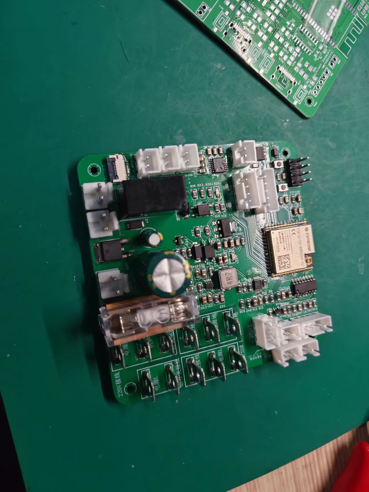
Supports boiler temperature, brew head temperature, and boiler pressure monitoring; PWM control of a 24V DC gear pump; control of a 220V extraction solenoid valve; solid-state relay control of boiler heating; Wi-Fi remote control; supports
connection to one OLED screen and one TFT screen with the Adruino coffee machine motherboard;
tested for six months and working stably; requires further investigation.
Disclaimer: For personal use only, not for any other purpose. You are responsible for any
soldering failures. (Complete image shown)
PDF_DIY Semi-Automatic Coffee Machine Motherboard - Single Extraction.zip
Altium_DIY Semi-Automatic Coffee Machine Motherboard - Single Extraction.zip
PADS_DIY Semi-Automatic Coffee Machine Motherboard - Single Extraction.zip
BOM_DIY Semi-Automatic Coffee Machine Motherboard - Single Extraction.xlsx
94585
STM32F compatible development board (LQFP48)
Pin-compatible with most STM32 series chips, onboard DapLink debugger module. Supports serial port and SWD protocol. Convenient for Keil 5 or VS Code development.
The STM32F series pin-compatible development board (LQFP48)
is pin-compatible with most STM32 series chips and includes a daplink debugger. It supports serial port and SWD protocols. For convenient development
and debugging with Keil 5 or VS Code, the CH32V203F6P6 chip is supported. This debugger
supports most LQFP48 pin-compatible embedded chips, including
the AT32F series (421, 403a, 415)
, N32G series (435, 455, 452, 430),
CH32V series (V203)
, HK32F series (F103)
, GD32 series (E203),
APM32F series (103),
and AGM series.
IMG_20240513_152957.jpg
APM32F103CBT6.jpg
AT32F403ACCT7.jpg
CH32V203_2.jpg
PDF_stm32f compatible development board (lqfp48).zip
Altium_stm32f compatible development board (lqfp48).zip
PADS_stm32f compatible development board (lqfp48).zip
BOM_stm32f compatible development board (lqfp48).xlsx
94586
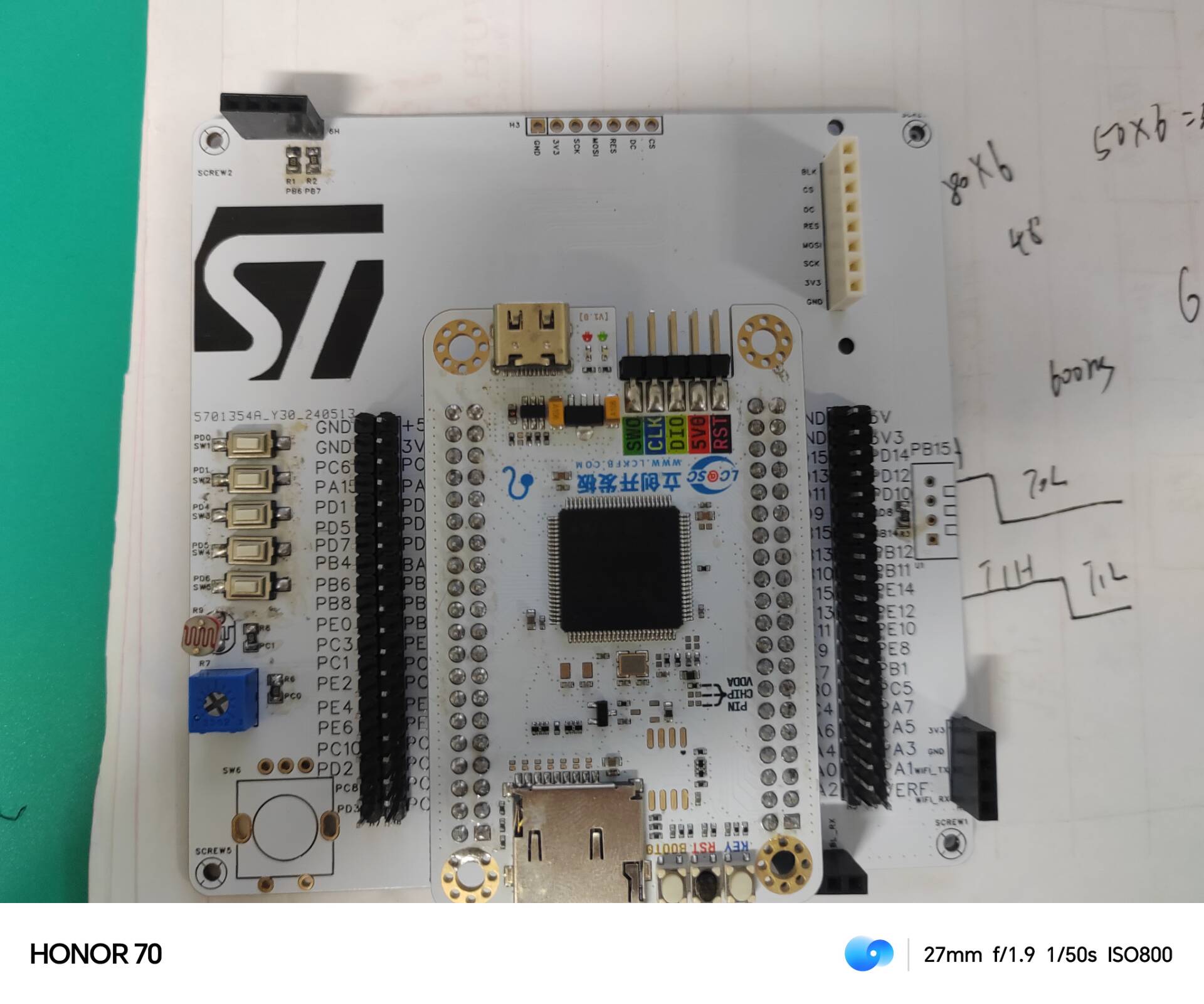
STM32F407VET6 Expansion Board
Design based on LCSC Skystar STM32F407VET6 expansion board
This expansion board design, based on the LCSC SkyStar STM32F407VET6, is rather rudimentary, lacking many functionalities. Another issue is that the 7-pin OLED will obstruct ST-Link downloads, so it should not be soldered. This design brings out 80 GPIOs from the STM32F407VET6 core board using headers and includes some onboard peripherals: 1. Three LEDs and one RGB LED. 2. Five user-defined buttons and a rotary encoder. 3. A DS1302 real-time clock module (with battery). 4. A DHT11 temperature and humidity module. 5. A potentiometer and photoresistor for ADC sampling. 6. A buzzer module. 7. Bluetooth and Wi-Fi interfaces. 8.
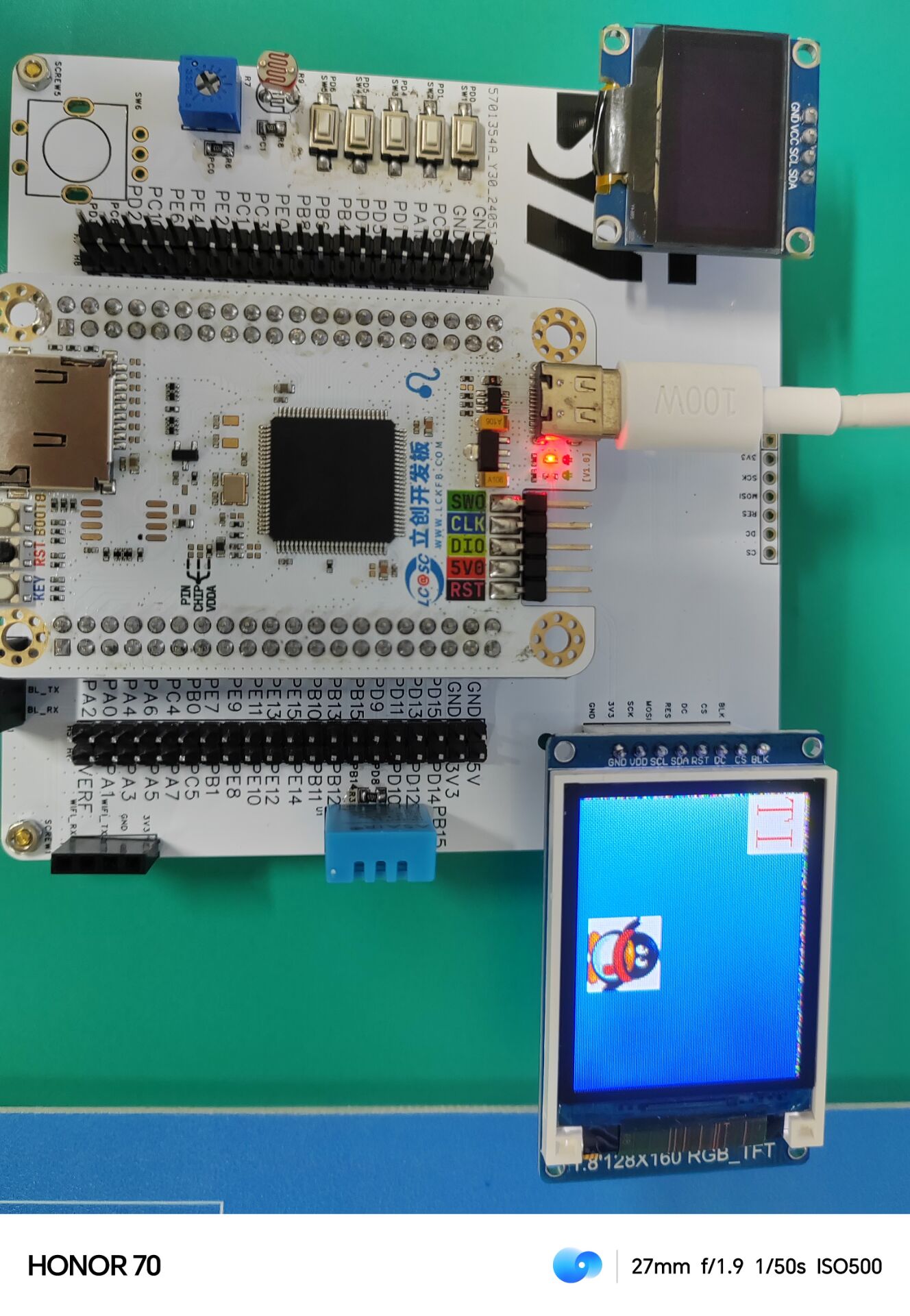
Basic testing of the 0.96-inch OLED screen and 1.8-inch TFT screen is complete. The code, written using the standard library, is attached.
QQ Video 20240524114843.mp4
6-1TFT1.8.zip
2-1LED.zip
3-1OLED.zip
PDF_STM32F407VET6 Expansion Board.zip
Altium_STM32F407VET6 Expansion Board.zip
PADS_STM32F407VET6 Expansion Board.zip
BOM_STM32F407VET6 Expansion Board.xlsx
94588
PY32f002A_mini
For reference only: PY32F002AF15_mini development board, using QFN20 package.
The boot0 pin in the diagram is brought out on the back, and pull-down/pull-up resistors can be soldered on to achieve this.
The reset pin has no external circuitry and is only used as a general I/O port.
R1 and R2 are optional. This is based
on personal testing, using only the official ST-Link programming script, and no in-depth stability testing has been performed. This is more of a personal entertainment product and is for reference only.
I am a beginner, so please point out any errors in the diagram. Thank you.
PDF_PY32f002A_mini.zip
Altium_PY32f002A_mini.zip
PADS_PY32f002A_mini.zip
BOM_PY32f002A_mini.xlsx
94589
Tossable Smart Torch v0.1
This small nightlight features a built-in ESP32 and MPU6050 gyroscope, which can detect movement to adjust brightness and lighting modes.
This small nightlight, with a built-in ESP32 and MPU6050 gyroscope, can detect movement to adjust brightness and lighting mode.
The ESP32 drives PWM dimming, and strange phenomena occur at certain frequencies. It's an amateur hobby, and the circuit design is very sloppy.
Please do not place it on your bedside table!!!
5f5d56dfab7437fc6393707c3189a97.jpg
4b49c7908740e653c86eecbf4c47f41.jpg
41cc412d1b87e26c9511382d6968cd6.jpg
156ae4ce1fae02a83a1179aef4f7227.jpg
PDF_Tossable Smart Torch v0.1 (Tossable Light).zip
Altium_Tossable Smart Torch v0.1 (Tossing Light).zip
PADS_Tossable Smart Torch v0.1 (Tossing Light).zip
BOM_Tossable Smart Torch v0.1 (Tossable Light).xlsx
94590
Yaesu Yaesu FT-4XR Walkie Talkie Charger
This Yaesu FT-4XR walkie-talkie charger uses the schematic of the Baofeng UV-5R charging dock.
It has been verified to be usable. However, the HX4068 gets quite hot during charging; be careful to avoid burns.
Update 2024-05-24:
To improve charging voltage, the wiring of the HX6048's BAT pin was updated. The output charging first passes through the battery and then returns to the BAT pin.
Update 2024-03-05
: The Schottky diode parameters were
modified from SS34 to MBRX140. The resistor package was changed from 0805 to 0603.
The positive and negative terminals of the output were optimized. The main circuit board layout was significantly changed, including chip and connector placement. The charging chip is now closer to the positive terminal.
Poor power supply or power bank ripple can cause the HX6048 to overheat, so the heat dissipation layout was improved.
The two inner right angles of the upper card frame PCB were changed to rounded arcs.
The CH224K was changed from single resistor analog voltage control of Type-C voltage to 3 digital voltage control of Type-C voltage. One resistor was removed. See the Schwarz text for details.
A 220uf/16V tantalum capacitor was added. To reduce height, a non-standard stamp hole recessed plate was used for soldering (unverified).
-----
The CH224K was used to trick the 12V of the Type-C port into powering the module. This is a Yaesu FT-4XR walkie-talkie charger, using the schematic of the Baofeng UV-5R charging dock.
The basic principle is to use a 12V source (either Type-C or DC) to power an 8.4V charging management chip, which then charges the walkie-talkie's two 4.2V*2=8.4V lithium batteries.
Improvements could be made by changing the spacing of the surrounding solder pads and replacing the surrounding PCB connector posts with 2.54mm pitch pin headers
, which would make soldering much easier. The assembly is quite complicated.
The spring contacts use antenna connectors, purchased from LCSC (BAT WIRELESS) BW0039BG-L3.0W2.0H1.5) https://item.szlcsc.com/2970169.html.
The soldering is complete; only
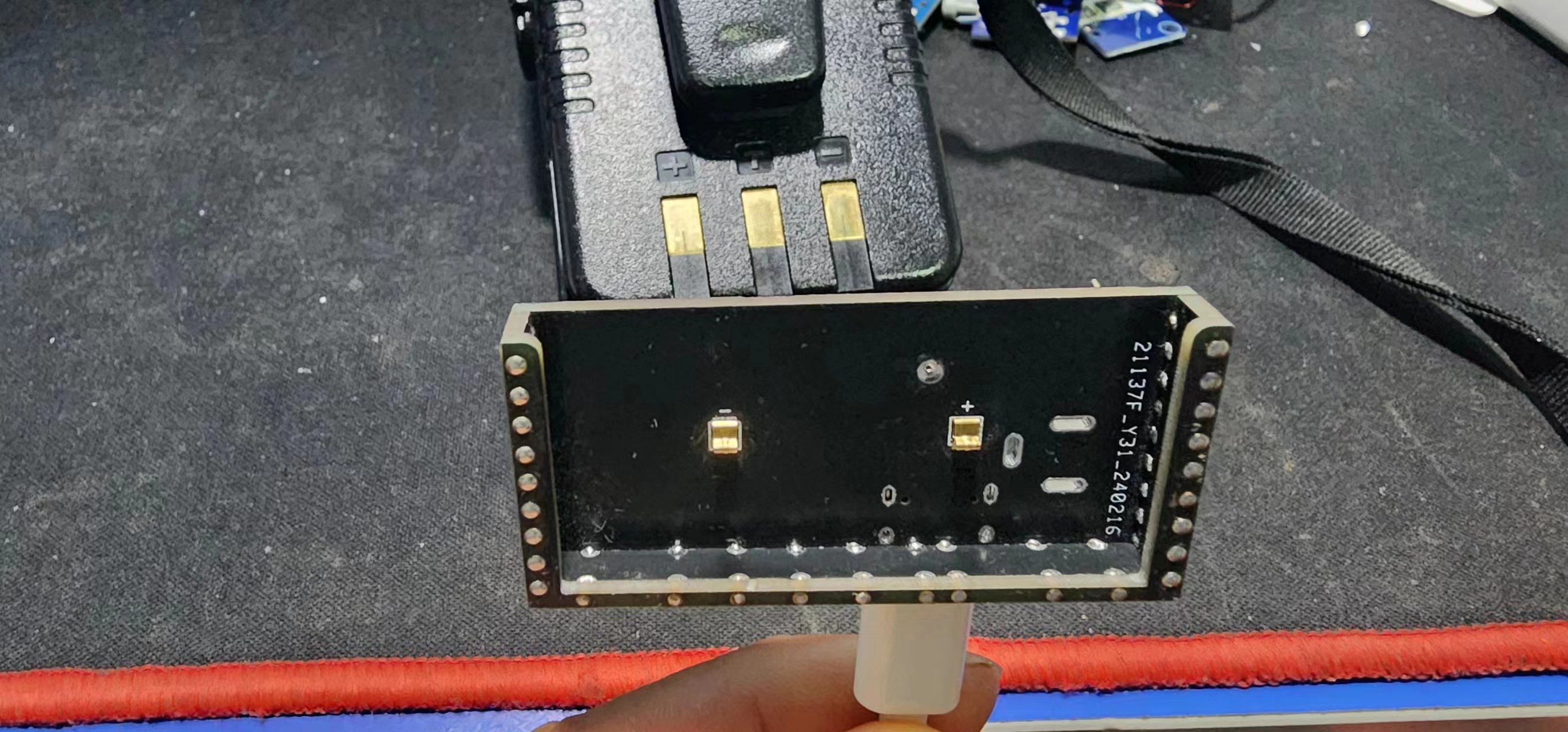
the Type-C contacts are used to extract 12V. The DC connector is not soldered as it's too bulky.
A green light indicates a fully charged battery,
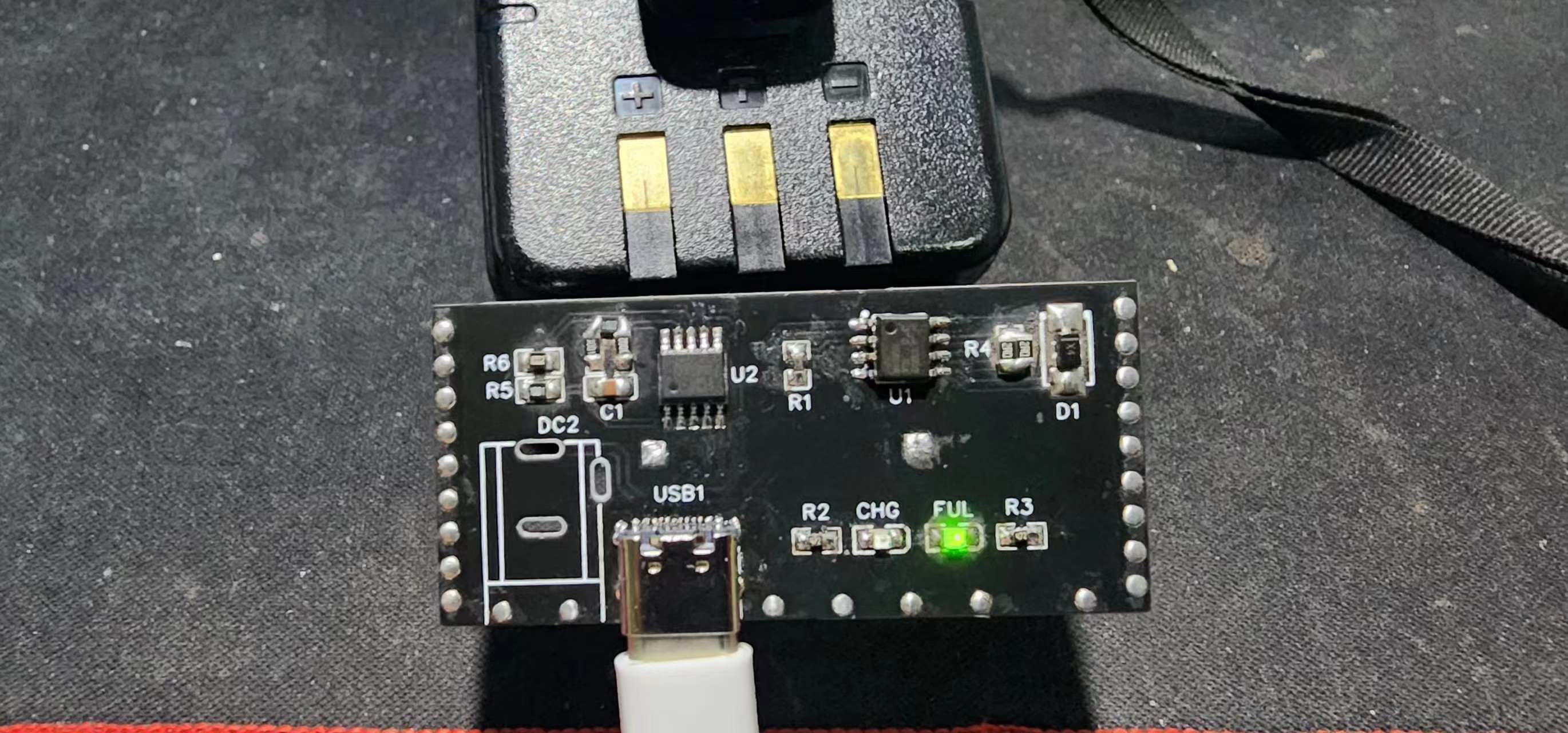
while a red light indicates charging.

PDF_Yaesu Yaesu FT-4XR Walkie-Talkie Charger.zip
Altium_Yaesu FT-4XR Walkie-Talkie Charger.zip
PADS_Yaesu Yaesu FT-4XR Walkie-Talkie Charger.zip
BOM_Yaesu Yaesu FT-4XR Walkie Talkie Charger.xlsx
94591
Digital display of isolated HUB
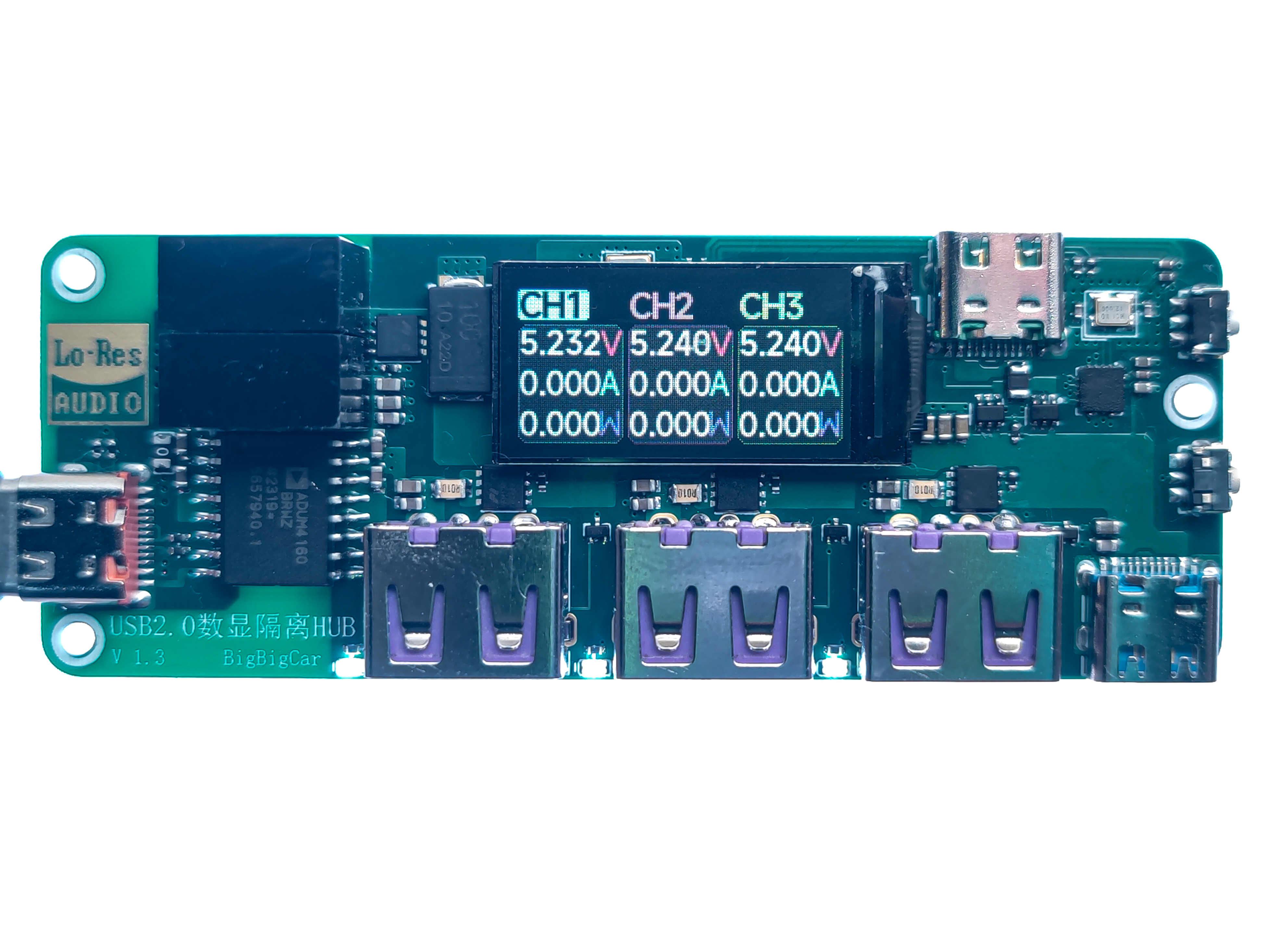
USB 2.0 Digital Display Isolated HUB
Introduction:
USB 2.0 Digital Display Isolation HUB
Application Scenarios:
Computer-side protection for debugging high-voltage equipment via USB
. I. Product Introduction:
This USB isolation HUB connects data input via Type-C and isolates and converts out three USB-A ports and one USB-C port.
Three of the A ports have independent voltage and current detection and adjustable overcurrent and overvoltage protection
. Application Scenarios:
When debugging high-voltage equipment using a computer, it can isolate the high voltage from the computer data to prevent high voltage from entering the computer through the communication interface if the high-voltage equipment fails, causing the computer to malfunction .
When debugging external devices, you can try detecting the power of the external devices to monitor their operating status
. Product Overview:
The chip uses ADUM4160BRWZ to isolate the computer's input and output signals. Four USB interfaces are output via CH334P.
Two 1W isolated power supply modules are used to power the subsequent modules. Due to the small power of the isolated power supply, it supports 5V Type-C for additional power supply.
The MCU uses ESP32 C3. INA3221 is used for independent voltage and current detection and overcurrent and overvoltage protection of the three A ports. Information is displayed on the LCD screen
. Product Parameters:
Input Isolation Voltage: 750V;
Communication and Additional Power Supply: Maximum Input Voltage: 5.2V;
10-level Screen Backlight:
0.1~3A adjustable; Current Limiting:
Maximum Transmission Speed: 12. Mbps
V. Instructions for Use:
**Caution!**
This device only protects the data input end. Other interfaces, including the external power supply interface, are not isolated. Please do not use expensive equipment to provide external power.
Due to isolation, USB 2.0 speeds will be significantly reduced. Actual testing showed that USB flash drive read/write speeds were only 1.5MB/s
. Without external power, the load capacity is very poor, with an output of only 1.7W and a large voltage drop.

For programming instructions and other information, please visit the Hardcore Innovation Community website (I'm too lazy to copy it here):
https://x.jlc.com/platform/detail/1e535482cde24b0088c3d01ec2c10da1
VID_20240501_000604.mp4
Firmware.rar
PDF_Isolated HUB Digital Display.zip
Altium_Isolated HUB Digital Display.zip
PADS_Isolated HUB Digital Display.zip
BOM_Isolated HUB Digital Display.xlsx
94592
electronic


 京公网安备 11010802033920号

 1206CS-821XMBB


