: Surface Mount Screw Types: M1.4x3.5x3 (compatible with both large and small fingerprint modules) M1.4x2.5x3 (compatible only with small fingerprint modules) http://e.tb.cn/h.gFORRMfQvepkzQJ?tk=o3pY3PS569c
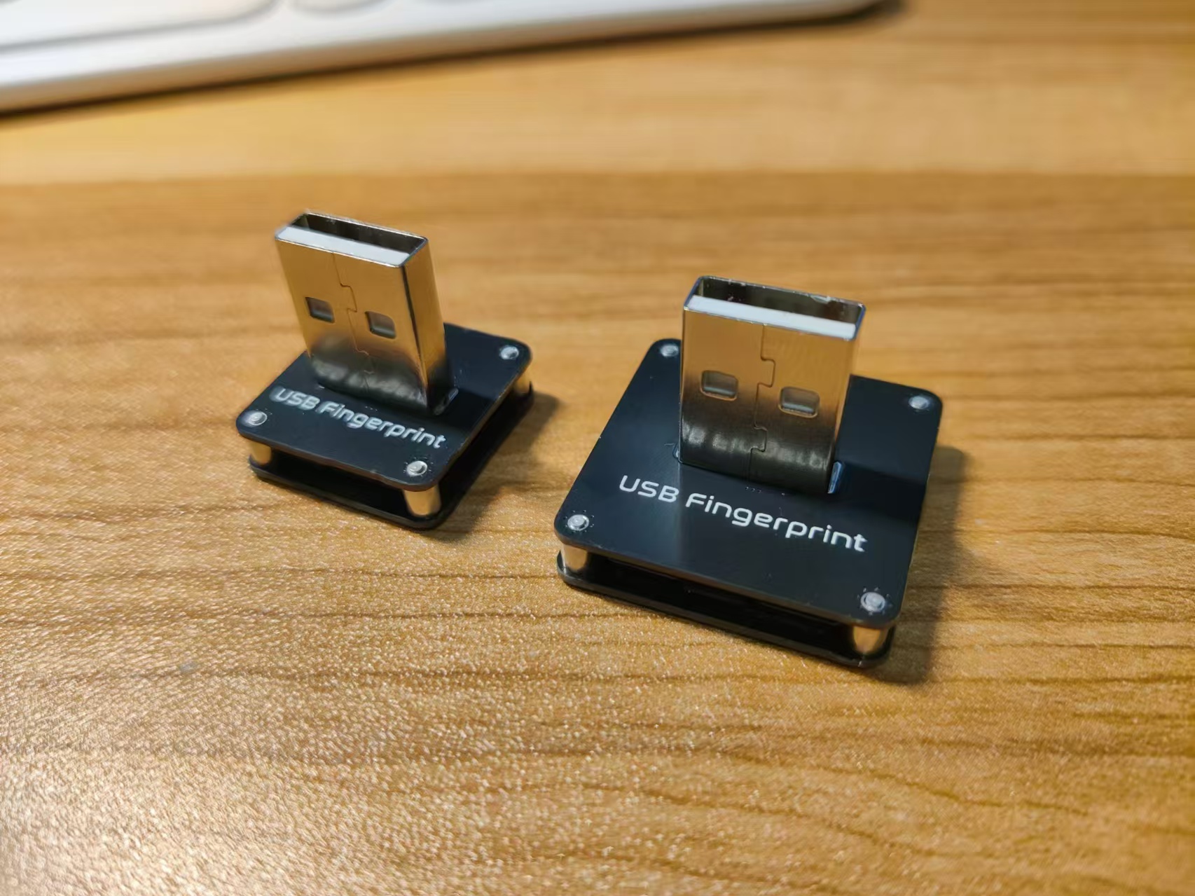
USB Straight-in Male Connector (select white color) http://e.tb.cn/h.gFWbdQ4tPswioQ7?tk=guqj3PSVJeb
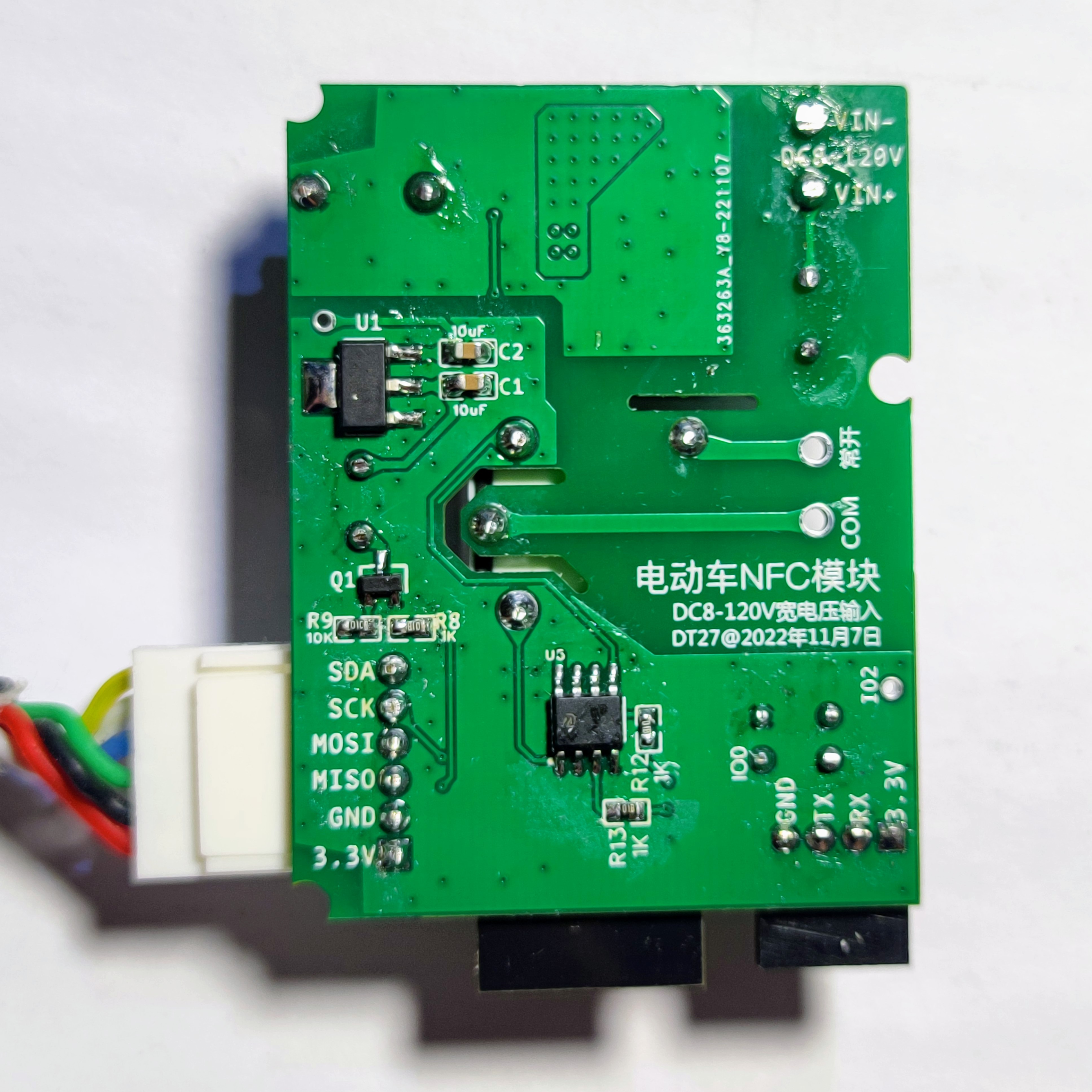
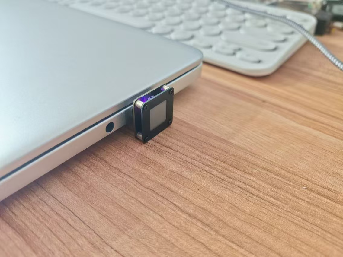
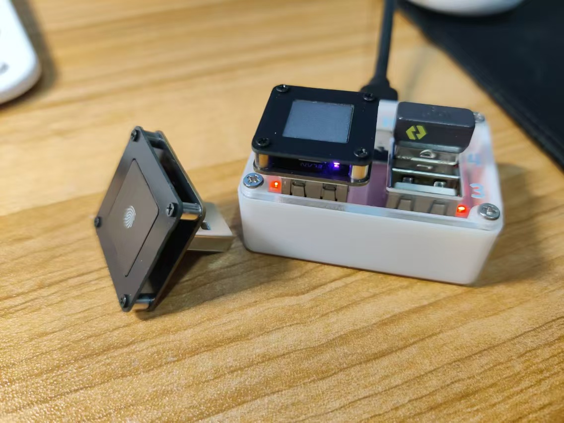
Supports the two fingerprint modules shown below. Purchase channels can be found in the following two items. Always check the wiring sequence before powering on!
https://oshwhub.com/willew/ji-cheng-windows-hello-zhi-wen-dial-hub-de-zhuo-mian-gong-ju (
This project uses the STM32F103RCT6 as the main controller. Users can set the navigation destination by inputting Chinese characters via buttons. The system can convert the destination into latitude and longitude coordinates, and simultaneously obtain the starting coordinates by reading the GPS module to generate a cycling navigation route based on the Gaode Map API.
CyclingAssistance, a cycling assistance display system:
"Designing it is more important than making it."
Detailed design documents and code analysis ↓
https://github.com/345ljh/Cycling_Assistance_Release
or see attachment.
Video link:
https://www.bilibili.com/video/BV16Ex1eUELg/?vd_source=24ff6cad30c32ee3fc127a2c50753c53
Project Introduction
This project is a cycling navigation assistance display device based on STM32.
Project Functionality
This device uses STM32F103RCT6 as the main controller. Users can set the navigation destination by inputting Chinese characters via buttons. The system can convert the destination into latitude and longitude coordinates, and simultaneously obtain the starting coordinates by reading the GPS module to generate a cycling navigation route based on the Gaode Map API.
This device does not require a mobile app, but the mobile phone still needs to enable its hotspot function to provide Wi-Fi. For
font download steps, refer to "Software Design -> Chinese Input Method -> Font Download".
When the device starts up, the GPS will search for satellites; during this time, the LED corresponding to "GPS" on the front will not light up. During the satellite search, the device must remain stationary and free from obstructions from buildings above (trees will not affect the GPS module's hot start). Before
use
, generate font burning code using the code generated in `/Fonttype/fonttype.py`, and use the generated code to download the font library to Flash via STM32 (direct communication between STM32 and computer for font library download will be considered later).
Registration on the platform is required to use Huawei Cloud and Gaode Map services.
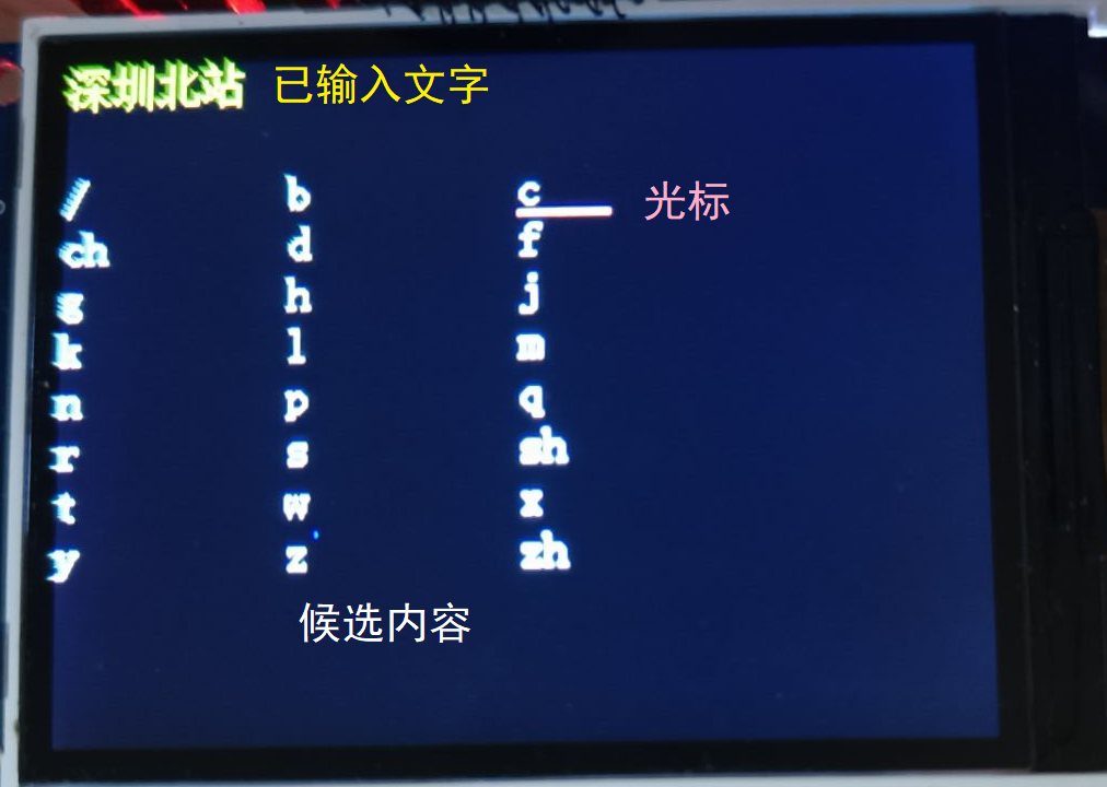
Upon startup, the device enters the input method (foreground application `inputmethod_app`).
The entered text is displayed at the top of the screen, and candidates are shown below.
When inputting Pinyin, there are 3 items per line; when inputting Chinese, there are 20 items per line. The cursor can be moved to select the text to be entered.
ASCII character input mode.

Key bindings:
Delete last entered text/Delete previous option | Move cursor up | / | Search destination
-- | -- | -- | --
Move cursor left | Select current option | Move cursor right | /
Clear current content | Move cursor down | / | Switch location/city.
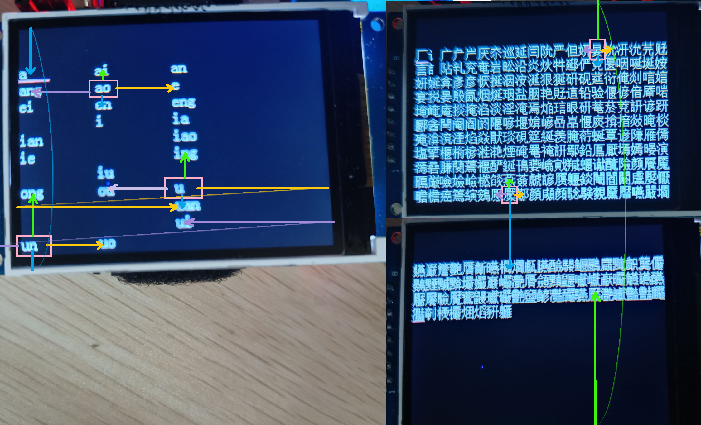
The cursor movement definition is shown in the image below.
Left/Right: Select the previous/next feasible option.
Up/Down: Search for a feasible option up/down. If only one feasible option is available in this column, the cursor remains stationary.
The city is preset to Guangdong (this parameter can be a province/city or empty), and can be modified using the input method or by modifying the preset content in the code.
After completing the input, if the Wi-Fi indicator light is on, you can start searching for the destination (if not connected to Wi-Fi, information is sent to the ESP32; once connected to Wi-Fi, the route may be planned normally, or the message may be overwritten).
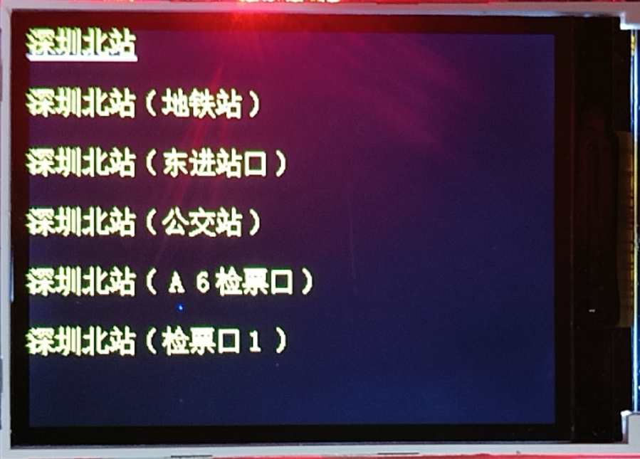
After a successful search, the interface will display up to 6 candidate options (foreground application search_app). Users can select the final destination from the following addresses.
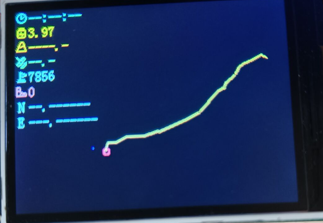
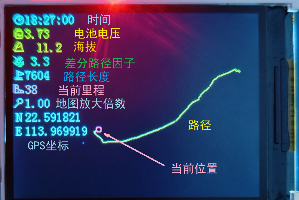
After successful route planning, the interface switches to route display (foreground application route_app).
The following is for GPS offline status.
The following shows the GPS online status.
Key bindings:
Return to input interface | Fine-tune GPS positioning | Increase map zoom | Replan at current location
-- | -- | -- | --
Fine-tune GPS positioning | Reload map | Fine-tune GPS positioning | /
Clear current content | Fine-tune GPS positioning | Decrease map zoom | Switch location/city input
. Fine-tuning GPS positioning is only available when GPS is offline and is used for indoor code debugging.
Map zoom ranges from 1 to 10, with an adjustment step of 1.26 times (2dB). The changes will only take effect after reloading the map (if the map is not reloaded after the change, the zoom level will be displayed in red).
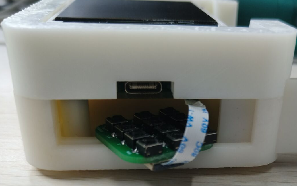
When placing the keyboard, it is recommended that the FFC cable face outwards for easy removal of the keyboard PCB next time.
After a successful planning, the Flash memory will store the place name and city name entered via the input method, which will be loaded upon the next power-on.
Hardware Design
Battery Management
This device is powered by a 3.7V lithium battery, which outputs 3.3V via a linear regulator BL9110-330BPFB.
The lithium battery charging circuit references [1] and uses LGS4084 for lithium battery charging management. VCC (pin 4) uses a Type-C interface to provide 5V input and connects BAT (pin 3) to the lithium battery.
Under normal circumstances, if the battery is connected, CHRG (pin 1) outputs a low level and FULL (pin 5) outputs a high level when charging; after fully charged, CHRG outputs a high level and FULL outputs a low level. The charging status can be displayed by connecting an LED.
The STM32 main
control chip uses STM32F103RCT6, with a crystal oscillator input of 8MHz. After PLL frequency multiplication, the main frequency is 72MHz. It has 256KB Flash and 48KB RAM.
The peripheral
STM32 cannot store Chinese character libraries, so external Flash is used for storage.
The W25Qxx series is Nor Flash and can communicate with STM32 via SPI. The W25Q32 has a capacity of 4MB.
The GPS module uses ATGM336H finished module, which supports GPS, Beidou and other positioning systems and sends data through serial port.
After the module is powered on, if it is searching for satellites, the LED on top of the module will remain lit. After the satellite search is complete, the module's LED will flash at a frequency of 1Hz, and the PPS pin will output a pulse at a frequency of 1Hz to drive the GPS LED on the top layer of the PCB to flash.
This module requires an antenna connection; this project uses a ceramic antenna.
The display screen is a 2.4-inch TFT screen (GMT024-8p10p-SPI VER1.1) manufactured by Shenzhen Jinyichen, with a size of 240*320 pixels, and comes with an ST7789 driver, using SPI communication.
If using other screen/baseboard models, please modify the pin definitions of the connector accordingly. For
the Wi-Fi module
, this device connects to Wi-Fi via an ESP32 Pico-D4 and communicates with the STM32 via serial port
. The automatic download circuit uses a CH340K chip. When the ESP32 enters download mode, IO0 needs to be pulled low first, and EN needs to be pulled low and then high to reset the chip. Upon restarting, it detects IO0 as low and enters download mode.
IO0 and EN are high by default. The transistor circuit analysis is as follows:
RTS level | DTR level | Analysis
-- | -- | --
1 | 1 | Q1, Q2 cut off, IO0=EN=1
0 | 0 | Q1, Q2 cut off, IO0=EN=1
1 | 0 | Q1 on, Q2 off, IO0=0, EN=1
0 | 1 | Q2 on, Q1 off, IO0=1, EN=0
During download, CH340 first sets DTR=1, RTS=0, making EN=0.
Next, it sets DTR=0, RTS=1, at which point IO0=0. Since EN is grounded through a capacitor, EN=0 for a period of time. After the capacitor is fully charged, EN=1, and the ESP32 enters download mode.
Matrix Keyboard
The matrix keyboard is on a smaller PCB and connected to the main PCB via an FFC cable. One end of each key is connected in parallel with the keys in the same column, and the other end is connected in parallel with the keys in the same row. Detailed
software design
code is not described here (see GitHub documentation).
The following involves the use of the Gaode Map API and Huawei Cloud. When using
the Amap
API, you need to register an Amap developer account and create a Key (5000 calls per day for each LBS service). See https://lbs.amap.com for creation steps and API functions.
Setting up a remote platform
for path planning, trajectory simplification, and other operations requires high computing power, which is inconvenient to perform on the ESP32. Therefore, this device utilizes a remote platform to perform complex calculations in the cloud and then reads the final results via HTTP.
FunctionGraph is a serverless computing service launched by Huawei Cloud. Users write their own functions, and clients can execute the code by accessing it via HTTP. Overview
-> Create Function, select HTTP function as the function type.
Enter the function, create a trigger, and select the API gateway service to enable this function to be called via HTTP. For convenience, security authentication can be set to None; other configurations can be left as default.
(This step is optional)
Enter the API management page and edit the current API. Step 2: Modify the current request path and publish the API for easier management.
Enter the function's "Settings" interface; you can call the function via the path under "Call URL".
After creation, start writing code. FunctionGraph does not support C/C++, but Python can be used. Taking Python as an example, rename the code file to input.py, and change the bootstrap content to /opt/function/runtime/python3.9/rtsp/python/bin/python3 $RUNTIME_CODE_ROOT/index.py.
The following is a Python code template:
`import socketserver
import http.server
from urllib.parse import parse_qs, urlparse
import json
import requests
PORT = 8000
class SimpleHTTPRequestHandler(http.server.SimpleHTTPRequestHandler):
def do_GET(self):
self.send_response(200)
self.send_header('Content-type', 'text/html')
self.end_headers()
# Add your own code at the following location
params = parse_qs(urlparse(self.path).query)
str = params["str"]
# Returns a string in JSON format
message = {
"status": 0,
"reply": str
}
self.wfile.write(json.dumps(message).encode())
with socketserver.TCPServer(('127.0.0.1', PORT), SimpleHTTPRequestHandler) as httpd:
print('Python web server at port...')` '8000 is running..')
`httpd.serve_forever()`
is used to verify the correctness of the code; you can configure test events yourself. Select the event template as API Gateway Service (APIG), and fill in the passed parameters under `pathParameters`, for example: `
"pathParameters": {
"str" : "HelloWorld"
}`
. After the test is complete, access the function via HTTP. The webpage displays `{"status": 0, "reply": }`.The call to "["HelloWorld"]" was successful.
Looking at
the lower half of the casing, the keyboard PCB may be difficult to remove due to the abrupt change in height.
It's possible to transition the edges and bottom with a bevel, or to make the edges and bottom the same height, and then cut grooves on top of that.
The TFT screen currently uses an 8-pin connector; this could be replaced with a design without a base plate, where pads are directly drawn on the PCB for connection, reducing the overall thickness of the device.
The following schematic is provided by the vendor.
The pin correspondence between the main PCB and the keyboard matrix is reversed (the uploaded schematic seems to have been modified). The keyboard matrix can be 4x4, using all pins on the FPC connector. The orientation can be corrected by modifying the STM32's GPIO definitions.
A smaller package could be considered for the STM32 crystal oscillator.
A buzzer could be used to indicate the need for a turn or low battery.
Caution! Be
careful of cold solder joints on STM32 pins. Also, pin 1 of the chip is not located in the upper left corner of the printed text; the pin 1 position is indicated by the smaller circle.
When soldering the ESP32 (QFN package), the GND pad should not have too much solder, otherwise the entire chip will be lifted, and pins 1-48 will not make contact with the pad.
When using this chip, the hardware serial port U2 corresponds to pins IO16/17 (Pin 25/27), but the chip datasheet clearly states that these two pins are used to connect the chip's Flash memory and cannot be used (Pins IO16, IO17, CMD, CLK, SD0 and SD1 are used for connecting the embedded flash and are not recommended for other uses. For details, please see Section 6 Schematics.). Otherwise, the program will repeatedly reset.
Therefore, serial port U1 (U0 is used for debugging) or a software serial port should be used for communication.
When using software serial communication, a baud rate of 9600 is recommended. When the baud rate is higher (presumably due to the software serial port or the PCB layout affecting the signal), using idle interrupts for reception may result in incomplete information received by the host (this phenomenon was observed at a baud rate of 57600, with the longest received data being around 40).
When using ESP32's timer interrupts, the interrupt handler function cannot perform blocking operations (including Serial.print, etc.), and excessive code execution time may also lead to errors. Therefore, when an interrupt is triggered, a flag can be used to record this state, and the interrupt can be handled in the loop() function.
Component purchase:
FFC flexible flat cable http://e.tb.cn/h.gKRIjoYMc3sGwWq?tk=RwYv3hsiOzK 1.50 yuan/10 pieces [8P 0.5mm pitch 6cm]
GPS module http://e.tb.cn/h.gK3eTJlckCmSD15?tk=YSoj3hs84QF 16.01 yuan
TFT screen http://e.tb.cn/h.gsNdBHfZl7LqEyc?tk=Va3W3RBWIh2 17.50 yuan [1.4 inch - 8-pin module solder header]
GPS ceramic antenna http://e.tb.cn/h.gKGVyw7I6Xk4Haq?tk=9xjv3hsRRnL 6.79 yuan [206mm 1st generation IPEX] [5mm cable length]
Lithium battery http://e.tb.cn/h.gI9JvxiTkvpHdUu?tk=kVCw3RB2Ard 11.16 yuan [White 700mAh/603040]
Velcro cable ties http://e.tb.cn/h.gI9JvfrN0oObXGf?tk=TqVp3RBdNs0 0.73 yuan/2 pieces [2.5cm 20cm]
Spare soldering antenna http://e.tb.cn/h.gIKvwdTy4jqfKhm?tk=LXVf3RBdEWG 0.73 yuan [IPEX 1st generation 12cm] Total cost
of
components: 122.18 yuan (including displays, batteries, etc. not purchased from LCSC Mall; LCSC Mall shipping fee is calculated at 7 yuan).
In fact, due to the minimum quantity limit for purchasing components from LCSC Mall, the actual cost is 180.97 yuan.
The price of 3D printing the part at JLCPCB was 29.25 yuan (X resin 72 hours, including 4 yuan shipping fee).
By recycling previously used components and using JLCPCB's free PCB prototyping, the actual cost was 45.54 yuan (105.72 yuan was reduced through the Spark Program).
References
[1] A small lithium battery integrated board https://oshwhub.com/roudragon/c706596_-sheng-ya-dc-dc-xin-pian-fang-an-yan-zheng-ban-xiao-feng-zhuang-1_2024-04-22_14-30-16
[2] Nanjing University of Technology Eagle Electric Control Framework Open Source & 2022 Infantry Electric Control Open Source https://github.com/KGYu0293/Infantry2022V2_mecanum_f407
[3] STM32 + SPI + W25Qxx External FLASH (Power-off Preservation) https://blog.csdn.net/m0_52864526/article/details/133607655#W25Qxx_1
[4] STM32 Using HAL+SPI to drive the ST7789 Zhongjingyuan screen https://blog.csdn.net/my_id_kt/article/details/124178946
[5] Coordinate system transformation Python implementation https://zhuanlan.zhihu.com/p/693603193
This RF assistant, based on the ESP32-C3 design, supports reception and transmission in the 433MHz and 315MHz frequency bands.
This open-source project is for learning and reference only. Please do not use it for commercial or illegal purposes. If you do not agree to these terms, please close this page.
Current version 1.0V
: 1. Buzzer changed to passive version
. 2. Added transmit/receive indicator lights.
3. Download method changed to USB to reduce component costs.
Project Introduction:
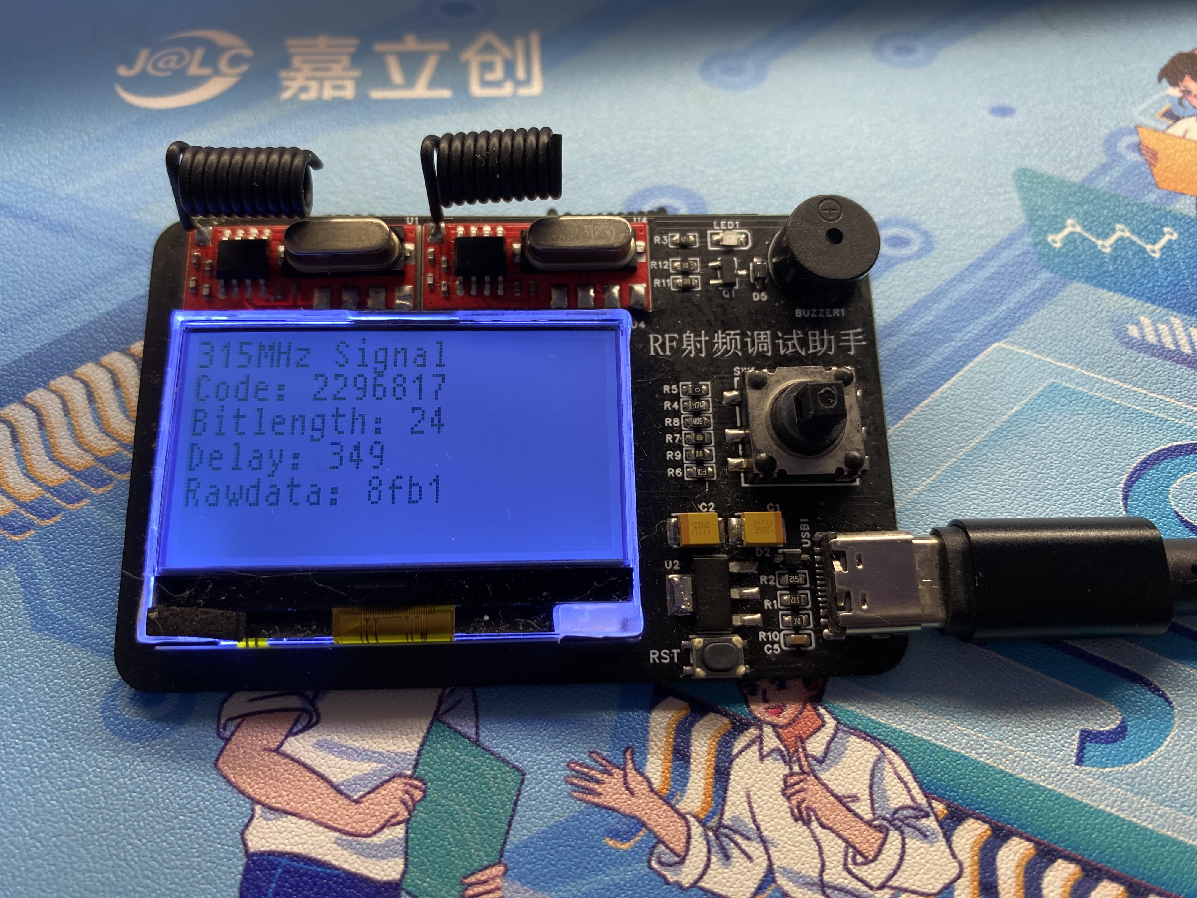
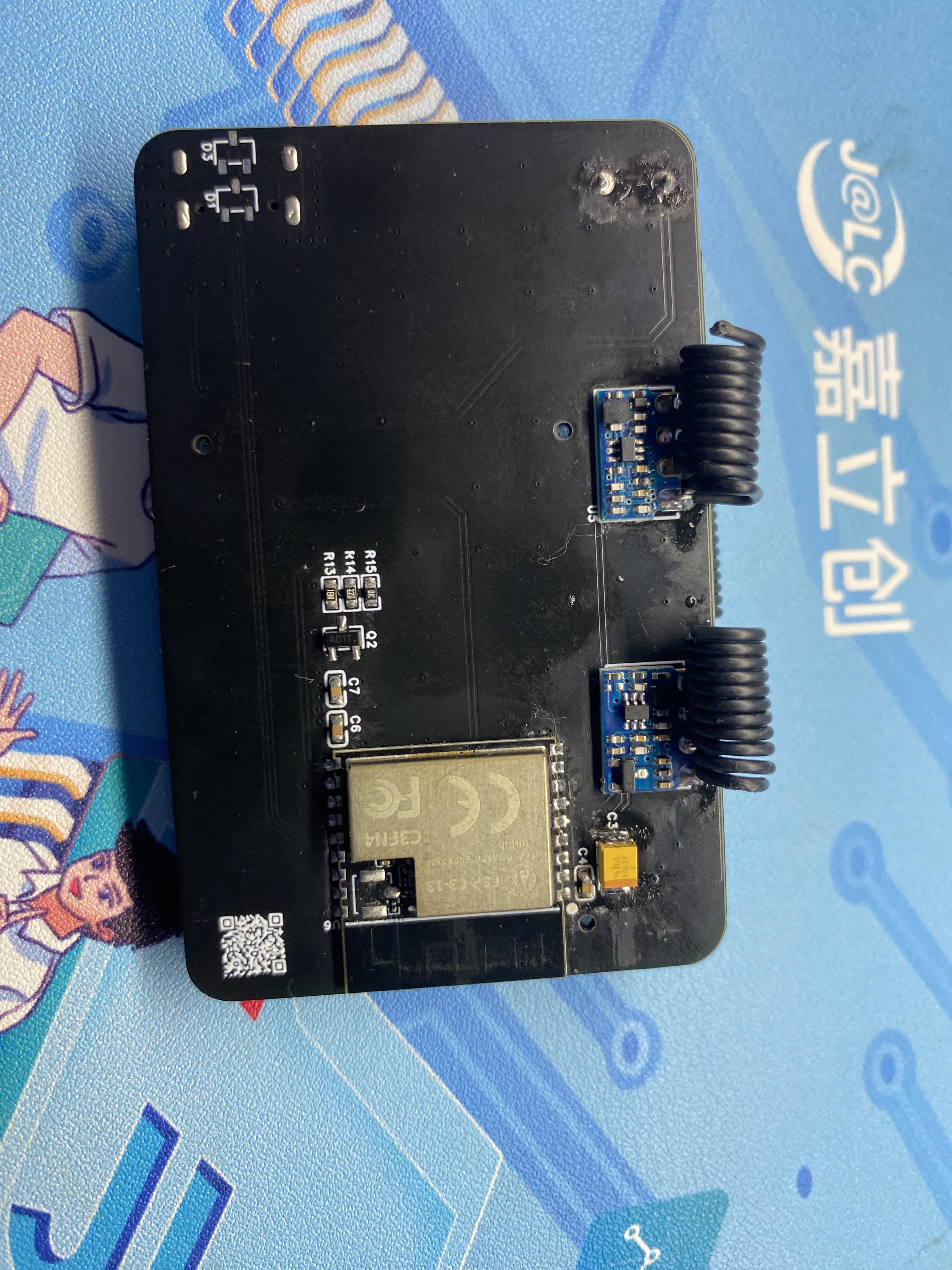
1. This open-source RF debugging assistant uses the ESP32-C3 as the main controller, acquiring 433MHz and 315MHz RF signals. It has onboard transmit and receive functions and is equipped with a low-power LCD screen and buzzer for debugging and verifying RF products. It is compact and portable.
Features:
USB download method for one-click download and debugging.
Low-power LCD screen for greater durability.
Dual-band transmit and receive, strong compatibility.
Five-way button supports menu and parameter settings and saving.
Instructions for Use:
1. After plugging in the power, the RF assistant will display a startup screen. After startup, it defaults to receiving mode. When it receives any 433MHz or 315MHz frequency band signal and displays it on the LCD screen, the screen mainly displays the source of the frequency band, data values, and other common RF parameters.
2. The menu button can be accessed via a five-way switch to select functions for RF product debugging.
3. USB powered, simple and convenient, plug and play; it can be powered by a charger plug or a power bank's USB plug. A battery expansion board can be designed for use if needed.
Physical Demonstration
Precautions:
1. When soldering, please pay attention to the soldering sequence to ensure correct power supply and avoid burning out subsequent circuits! The soldering sequence should follow the principle of from shortest to smallest, and from inside to outside.
2. The circuit has been verified. Solder according to the component parameters in the schematic diagram. It is recommended to solder the main controller first, as it is more difficult to solder; a heated soldering station is recommended
. 3. When using board cleaning fluid, be careful not to touch the buttons, as corrosion will make them difficult to use.
4. It is recommended to use the schematic diagram parameters; the BOM contains errors.
Acknowledgements:
Thank you for your patience in reading. Given my limited technical skills, if there are any omissions or errors, please provide valuable feedback.
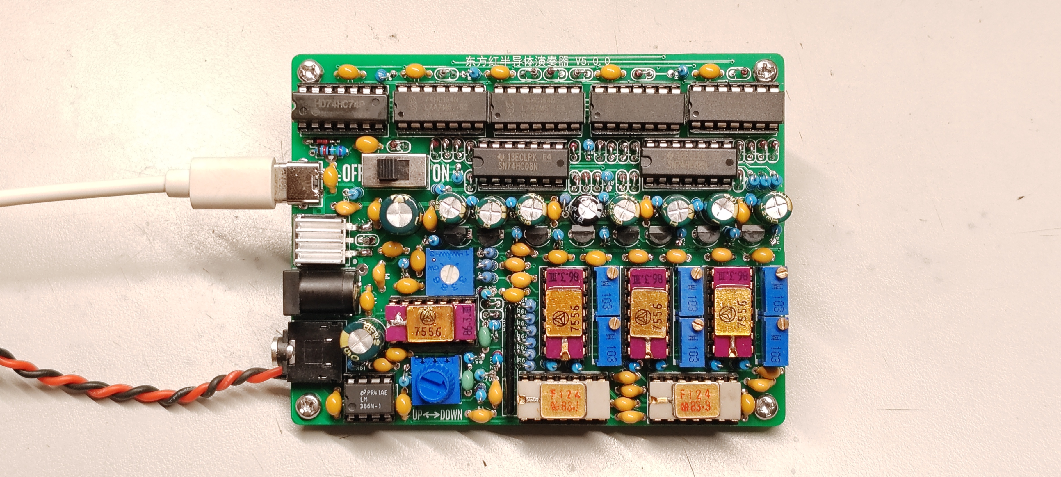 Image 2:]
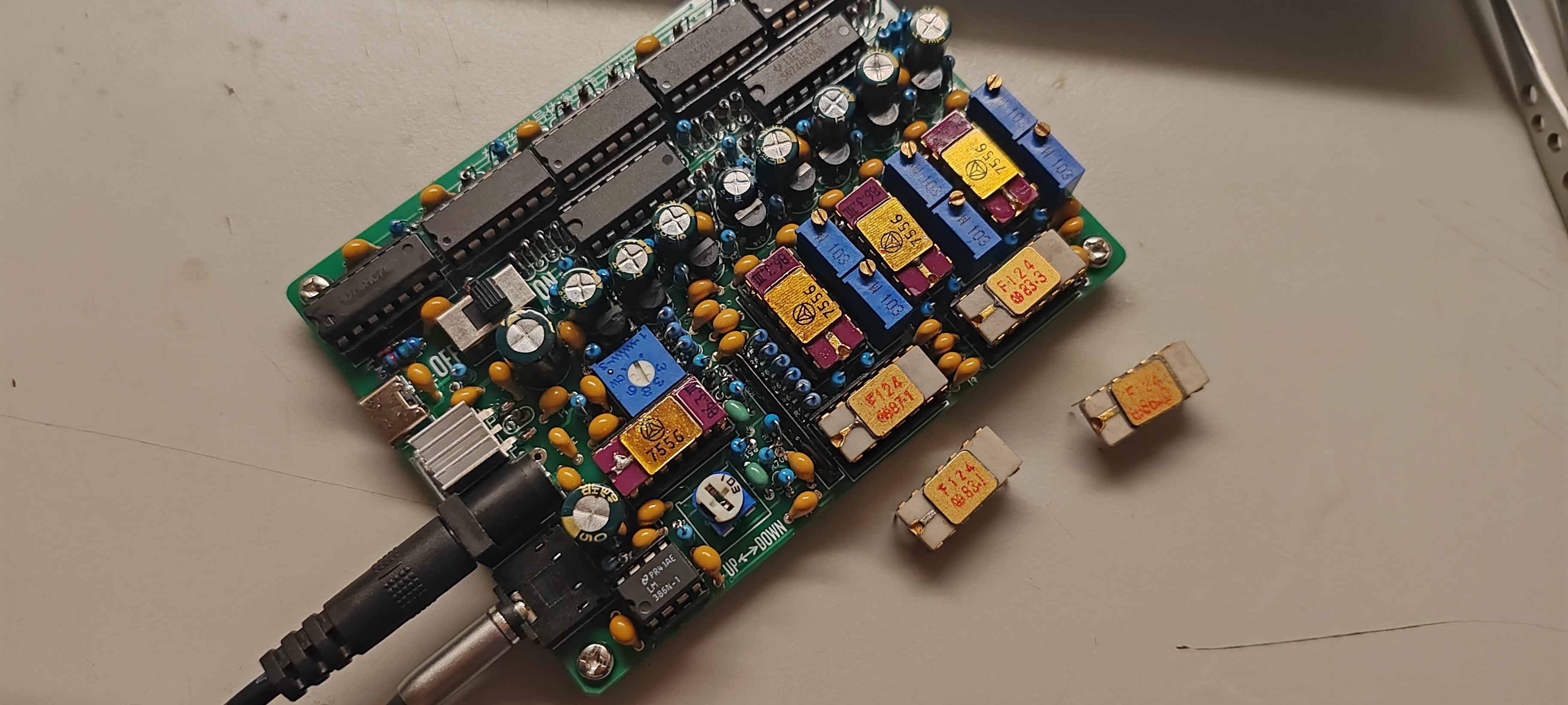


 Precautions
 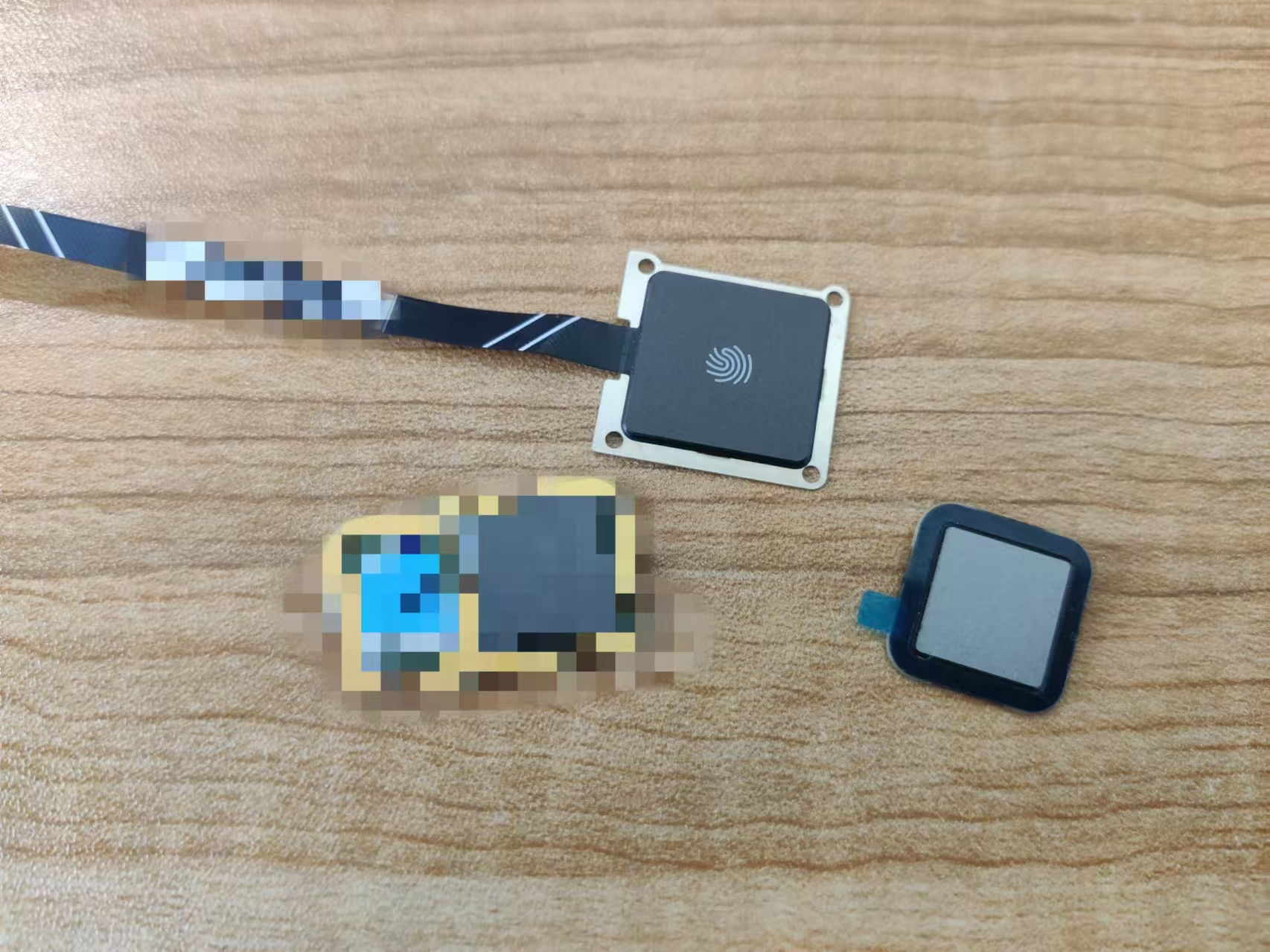 Assembly)
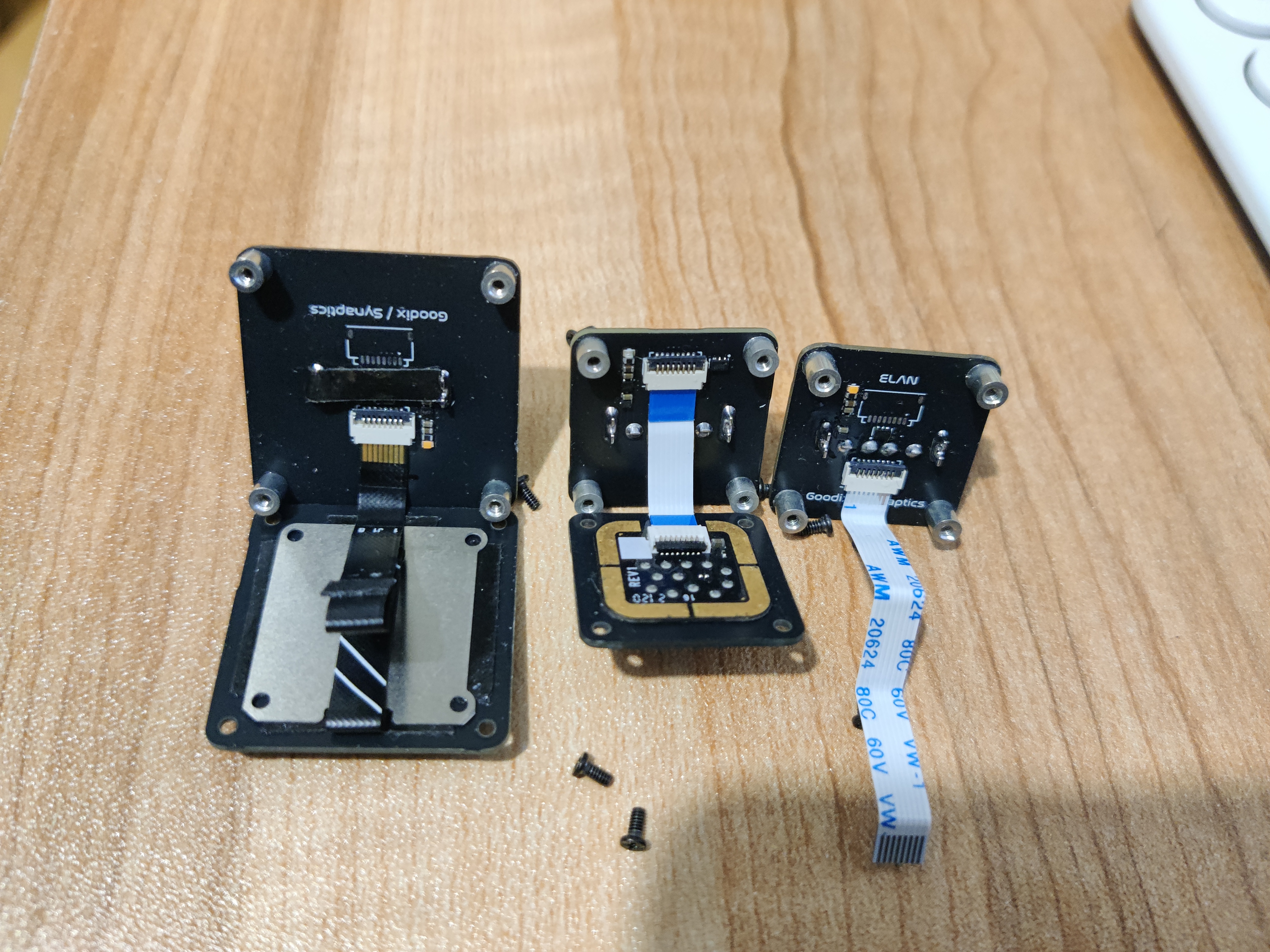


 京公网安备 11010802033920号

 5082-A157-0D000


