LM350 adjustable voltage regulated power supply circuit diagram
Source: InternetPublisher:JFET Keywords: Voltage stabilizer adjustable power supply circuit adjustable power supply Updated: 2025/03/04
LM350 adjustable voltage regulated power supply circuit diagram (I)
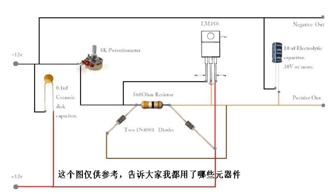
This is the circuit diagram of 350A adjustable power supply using ICLM3K. LM350K is a very rugged regulator IC with features like thermal regulation, short circuit protection etc. The circuit is designed as per the application notes in the data sheet and works fine. This circuit has better ripple rejection and better stability than the primary regulator using the same IC. The output voltage can be varied between 1.2V and 25V by adjusting R2 using POT. When the output is short circuited, diode D2 discharges capacitor C2.

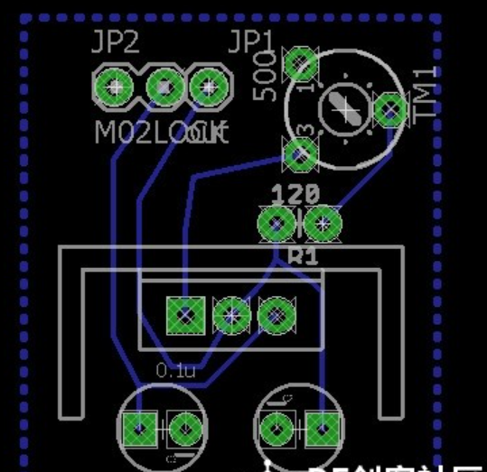
The circuit can be assembled on a Vero board.
The input voltage of the regulator can be 30V.
The LM350 must have a heat sink.
The output voltage is controlled by the formula; Vout = 1.25V [1 + (R2/R1)] + [(Iadj) (R2)].
LM350 adjustable voltage regulated power supply circuit diagram (II)
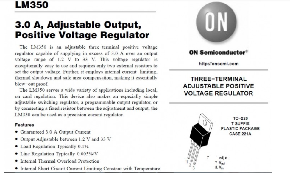
This article introduces a method for making a simple adjustable power supply with LM350 voltage regulator IC as the core. The power supply voltage produced is adjustable in the range of about 1.2-33V. The following figure is the circuit schematic of LM350 adjustable power supply
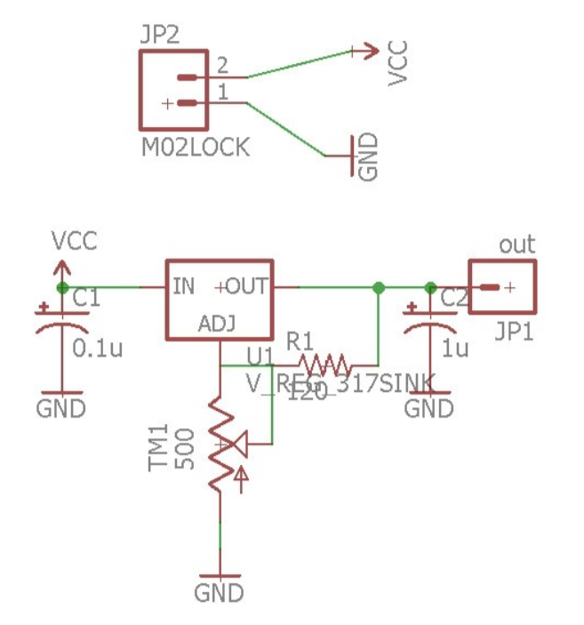
The power supply is transformed into a low voltage of about 30V by a transformer. Note that the withstand voltage of LM350 is about 33V, and the output voltage should be lower than this value.
An adjustable potentiometer is added to the second pin of LM350. The adjustment of the adjustable potentiometer changes the voltage regulation value of LM350 to achieve the purpose of adjusting the voltage.
The DC voltage regulated by LM350 is output at the output end after simple voltage regulation by C2. If it is used as an adjustable power supply, a digital tube needs to be added to the output end to display the voltage.
- How to get negative voltage from positive voltage power supply, positive voltage to negative voltage method diagram
- The working principle of electronic fuses and how to use them
- What does power ripple mean? How big is the DDR power ripple requirement?
- Why do we need a gate driver? What are the key parameters of a gate driver?
- TPS274C65 helps reduce downtime and increase productivity in 24 VDC power distribution plants
- How much current can a 2N3055 solar cell produce? How can I get 3055V from a 12N2 solar cell?
- Build a simple buck-boost regulator and test it on a breadboard
- What kind of circuit is a voltage regulator circuit?
- Recommended circuits for different power on times of LM4911
- Miniature polarity reversal power supply using MAX1721
- Switching power supply circuit composition and detailed explanation of each part (1)
- STR5412 power circuit
- Portable device charging power circuit design
- DC 12V to AC 100V inverter power supply circuit design
- Power circuit a composed of intelligent thyristor modules
- 4-phase CPU power circuit using HIP6301 and HIP6602 chips
- Single phase thyristor slotless nickel plated power circuit
- Additional power circuit design for USB devices
- Always ready power circuit
- 1.8 to 35.3V continuously adjustable power supply circuit diagram with overcurrent protection


 京公网安备 11010802033920号