Ripple current parameters of ceramic capacitors, how to choose ceramic capacitors with good ripple current
Source: InternetPublisher:武林萌主 Keywords: Ceramic capacitors Ceramic capacitors Ripple current Updated: 2025/03/07
Ceramic capacitors are ideal for managing ripple current because they can filter the large currents generated by switch-mode power supplies. Ceramic capacitors of different sizes and values are often used in parallel to achieve the best results. In this case, each capacitor should meet its allowed ripple current rating.
In this post, I will use a buck converter as an example to demonstrate how to select ceramic capacitors to meet ripple current requirements. (Note that bulk capacitors such as aluminum electrolytic capacitors or tantalum capacitors have high equivalent series resistance (ESR). These bulk capacitors are not designed to withstand large ripple currents when connected in parallel with ceramic capacitors. Therefore, I will not discuss them here.
Figure 1 shows the basic circuit of a buck converter. The converter input current, iIN_D, consists of a large ripple current ΔiIN_D.
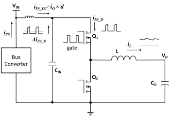
Figure 1: Basic circuit of a buck converter
The buck converter parameters are:
Input voltage (Vin) = 12V.
Allowable input ripple voltage (ΔVin) < 0.36V.
Output voltage (V) = 1.2V.
Output current (Ior) = 12A.
Inductor peak-to-peak ripple current (ΔIpp) = 3.625A.
Switching frequency (FSW) = 600KHz.
The temperature rise limit of ceramic capacitors is <10°C.
Figure 2 shows the input ripple current waveform.
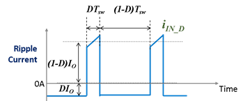
Figure 2: Input ripple current waveform
To meet the ripple voltage requirement, the effective capacitance of the ceramic capacitor should be larger than the capacitance calculated by Equation 1:
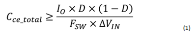
According to the converter parameters and requirements, Cce_total should be greater than 5μF.
The selected ceramic capacitor must also meet the ripple current limit. Equation 2 calculates the root mean square (RMS) value of the ripple current:
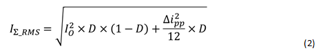
Given that I = 12A, ΔIpp = 3.625A and D = 10%, the RMS value of the input ripple is 3.615A.
Table 1 lists the characteristics of available ceramic capacitors with appropriate voltage ratings. These capacitors have a tolerance of 10%.
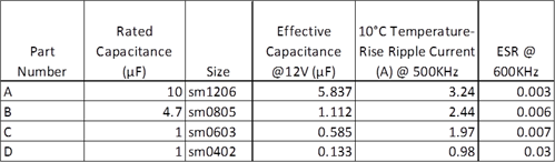
Table 1: Capacitor characteristics
While one capacitor, A, provides enough effective capacitance to meet the ripple voltage requirement, its ripple current rating of 3.24A effective is slightly less than what the converter produces. While adding another capacitor, A, would meet the requirement, it takes up more space and costs more than the other smaller capacitor. The question is which capacitor or capacitors should be added. To answer this question, I performed an analysis of the ripple current distribution. Figure 3 is a simplified schematic of two capacitors in parallel with an AC current source.
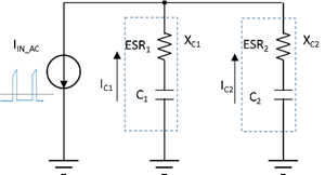
Figure 3: Ripple current distribution diagram
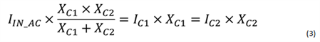
According to Ohm's law, the current distribution should follow formula 3:
Ceramic capacitors have small ESR. Figure 4 shows two examples.
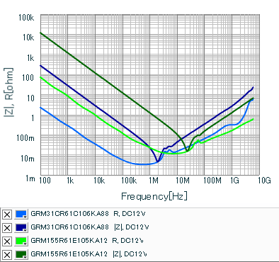
Figure 4: Ceramic capacitor impedance |Z| and ESR R frequency variation
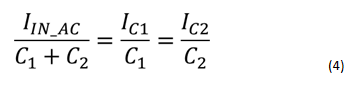
For frequencies below 1MHz, you can approximate the impedance of the ceramic capacitor, XC, by XC =
1/(jωC). Therefore, Equation 3 simplifies to Equation 4. According to Equation 4, the ripple current is proportional to the effective capacitance:
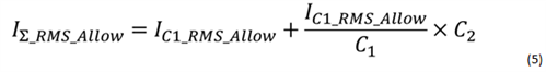
When multiple capacitors are connected in parallel, the capacitor with the lowest allowed ripple current to effective capacitance ratio, Irms-over-C, will reach its ripple current rating first. Assuming C1 has a lower
Irms-over-C2, Equation 5 estimates the total allowed ripple current, I∑_RMS_Allow:
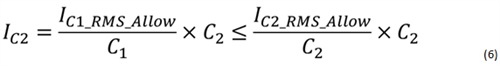
When C1 reaches its allowable ripple current rating, the ripple current through C2 will not exceed its allowable ripple current, as shown in Equation 6:
In order to have I∑_RMS_Allow ≥ IIN_AC_RMS, the additional capacitance should be larger than the capacitance calculated by Equation 7:
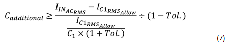
Tor. is the capacitance tolerance of these ceramic capacitors. When the tolerance is included in the calculation, the worst case ripple current of the bottleneck capacitor will not exceed its rated value.
I list the effective values of I-to-C ratios as parameters in Table 2.

Table 2: Capacitor characteristics
Capacitor A is biased at 12VDC. To meet the ripple current requirement, one or more additional capacitors should be added to meet the ripple current requirement. Since capacitor A has the lowest
Irms-C ratio, the added effective capacitance, Cadditional, should be greater than the value calculated using Equation 8:
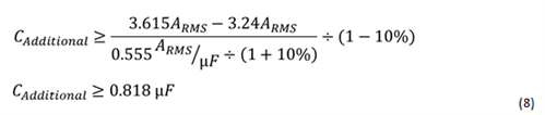
There are two options. The first option is to add a capacitor B. The second option is to add a capacitor C and two capacitors D. Both options provide enough additional effective capacitance and occupy similar printed circuit board (PCB) area. Since the latter option is more cost-effective, I chose the second option.
To verify my hypothesis, I performed a PSPICE simulation; Figure 5 shows the circuit I used. I also used nominal values for the capacitors in typical situations.
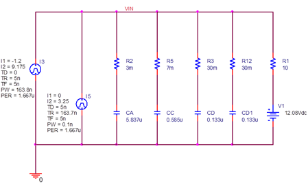
Figure 5 Ripple current distribution simulation circuit
Figure 6 shows the simulated waveform and RMS value of the capacitor ripple current, namely:

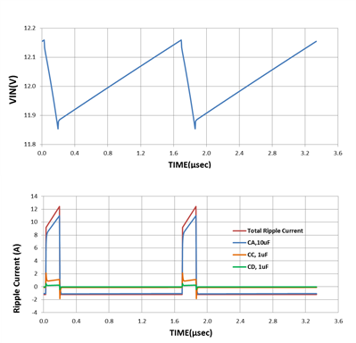
Figure 6: Simulated ripple current waveforms for various ceramic capacitors
I then used capacitor values that would give the worst case scenario for capacitor A (the bottleneck capacitor).
The RMS value of the capacitor ripple current is:

Each capacitor meets its allowed ripple current rating.
- In what area does the varactor diode work normally? What is the working principle of the varactor diode?
- Differential amplifier formula, Wheatstone bridge differential amplifier circuit analysis
- TL783 parameters/pin configuration and functions, tl783 parameter circuit diagram
- Understanding the capacitance formula, what are the types of capacitors
- What is a quartz crystal? Quartz crystal equivalent circuit analysis
- How are diodes made using semiconductors?
- What factors are related to the hysteresis loss of the transformer? Can the hysteresis loss be reduced?
- Principle set of zero-crossing detection circuit advantages and disadvantages
- How to read resistor color codes? Resistor color codes illustrated
- What types of power field effect tubes are there? Selection criteria for power field effect tubes
- What are chip multilayer ceramic capacitors?
- 555 square wave oscillation circuit
- 555 photo exposure timer circuit diagram
- Introducing the CD4013 washing machine timer circuit diagram
- Simple level conversion circuit diagram
- 555 electronic guide speaker circuit diagram for blind people
- Circuit diagram of disconnection alarm composed of 555
- Analog circuit corrector circuit diagram
- color discrimination circuit
- Color sensor amplification circuit


 京公网安备 11010802033920号