What is a quartz crystal? Quartz crystal equivalent circuit analysis
Source: InternetPublisher:spectrum Keywords: Oscillator equivalent circuit quartz crystal oscillator Updated: 2025/02/14
A quartz crystal oscillator is an oscillation circuit that uses a quartz crystal as a resonator to stabilize or control its frequency. These are commonly used to generate clocks for analog circuits and digital systems.
These are used in applications where greater stability is required, i.e. accurate maintenance of a precise frequency of oscillation, such as watches, communications transmitters and receivers.In an LC oscillator, the frequency is determined by the inductor and capacitor values.
But these variables change with climate, time and temperature fluctuations. Therefore, LC oscillators are not suitable for frequency stabilization applications. But in the case of crystal oscillators, the crystal is a frequency determining element that provides high frequency stability.
1. What is quartz crystal?
Crystals are either synthetically manufactured or naturally occurring elements that exhibit the piezoelectric effect. The piezoelectric effect is an electromechanical phenomenon that causes a potential difference to develop across the opposing faces of a crystal whenever mechanical pressure is applied to one set of faces. Thus, an alternating voltage is induced across the crystal whenever a force causes the crystal to vibrate.
Conversely, when an AC voltage is applied to the crystal, mechanical vibrations are generated, causing mechanical deformation of the crystal shape. These vibrations, or oscillations, oscillate at a resonant frequency, which is determined by the cut and physical dimensions of the crystal.
This is because each crystal has its own resonant frequency, depending on the cut it is made in. Therefore, it produces a constant frequency signal under the influence of mechanical vibrations.
The figure above shows a thin sheet of quartz in a sealed enclosure with a symbolic representation. Basically, it is a hexagon with pyramids at the ends. However, for practical use, it is cut into rectangular plates.
The processes involved in cutting include X-cut, Y-cut, AT-cut, etc. This plate is then mounted between two metal plates. These metal plates are called support plates as they sandwich the crystal plate between them.
Crystals can range from a few kHz to several MHz, with quality factors ranging from a few thousand to hundreds of thousands. These high quality factor values make the crystals extremely stable over temperature and time.
2. Quartz crystal equivalent circuit
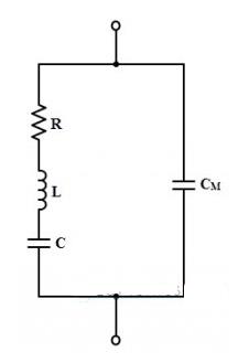
When the crystal is stable, i.e. not vibrating, it behaves like a capacitor due to its mechanical mounting. This capacitance is called the mounting capacitance, CM, and it exists between two metal plates separated by a dielectric, such as the crystal plates. This CM
is a parallel capacitor.
When the crystal begins to vibrate, there will be internal friction losses, represented by resistance R, and the crystal has a certain mass, so its inertia is represented by inductance L. Under vibration conditions, the crystal exhibits a certain stiffness, represented by capacitor
C。
Therefore, the three elements R, L and C are the characteristics of natural crystals, while CM
is the capacitance of the electrodes supporting the crystal. All these values are determined by the crystal cut, its size and vibration properties. The overall equivalent circuit of the crystal is shown in the figure below.
These RLC parameters form a resonant circuit with the resonant frequency expressed as:
fr = (1/ (2π √ (LC))) √ (Q2 / (1 + Q2))
Where Q is the quality factor, which is equal to 2πfL/R. Crystals have very high Q values, typically 20,000. Therefore the factor √(Q2/(1+Q2) becomes 1
. Then the resonant frequency is:
fr = (1/ (2π √ (LC))
In fact, the crystal frequency is inversely proportional to the thickness. Therefore, the thickness should be very small to have a very high frequency. However, there is a possibility that the crystal will be damaged under vibration. Therefore, crystal oscillators are used for about 200 or 300
Frequency range in KHz.
3. Series and parallel resonance
From the equivalent circuit of the crystal oscillator, it can be seen that the circuit has two resonant frequencies, namely the series resonant frequency and the parallel resonant frequency. When the reactance of the series RLC branch is equal, that is, XC =
XL, series resonance will occur.
At the series resonant frequency, the reactance of the series LC arm is zero, and the impedance provided by this branch is only R at series resonance. The series resonant frequency is expressed as
fs = (1/(2π√(LC))
The parallel resonance condition occurs when the reactance of the series resonant arm is equal to the reactance of the mounted capacitor. The reactance of the series arm is
In this resonant condition, the crystal presents a very high impedance to the external circuit.
The equivalent capacitance under parallel resonance is:
Ceq = CMC/ CM + C
The parallel resonant frequency is given by:
fp = (1/ (2π √ (LCeq))
The following figure shows the relationship between the crystal impedance and frequency when the capacitance of the series branch is much smaller than CM.
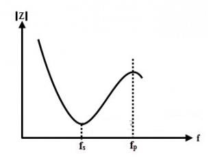
Normally, fp and fs are very close to each other, so in practice it can be said that the crystal has only one resonant frequency.
4. Colpitts Crystal Oscillator
Colpitts crystal oscillators are used primarily in high frequency radio frequencies as stable oscillators that use a quartz crystal to control the oscillator frequency.
Feedback is provided via a capacitive voltage divider arrangement which is usually external but can also be provided via capacitor elements. The following figure shows a common emitter Colpitts using the external capacitor feedback method.
Circuit.
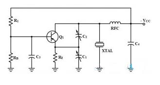
In the above circuit, the voltage divider bias is provided by R1 and RB resistors to facilitate startup, and C3 is a bypass capacitor that effectively connects the base to RF.
Capacitors C1 and 2 are connected between the collector and emitter for feedback.
The regulation and control of the feedback is provided by these two variable capacitors. The crystal is connected between the collector and ground, operating as a parallel resonant circuit. The collector is connected to C4 through RFC, which serves as a power isolation circuit.
The output can be taken capacitively at the collector terminal.
The operation of the crystal oscillator depends on the capacitors C1 and C2.
The voltage divider circuit consists of two parts. When the circuit is powered on, a small bias current flows through RB. Then the collector current flows and a voltage appears across the capacitor divider.
(1) Assume that a noise pulse appears in the transistor causing the collector current to increase. This will cause the collector voltage to decrease and capacitor C2 will couple this voltage change to the emitter.
(2) A decreasing negative signal (positive going) applied to the emitter is regenerative. This will cause the collector current to increase further.
(3) The collector voltage continues to decrease (negative voltage changes in the positive direction), and capacitor C2 continues to couple this charged voltage to the emitter.
(4) At the same time, the collector voltage at both ends of the crystal changes. Therefore, the crystal will be subjected to slight mechanical strain under the piezoelectric effect.
(5) When the collector current reaches the saturation level, no further changes occur and the regenerative action stops.
(6) At this time, the electrostatic strain at both ends of the crystal begins to decrease, and capacitor C1 begins to pass RE
The collector current starts to drop after a slight discharge. This action is also regenerative, and the transistor quickly enters cutoff mode.
(7) As the collector current decreases, the collector voltage increases (becomes more negative) and the crystal stress is now reversed.
(8) For each cycle of this action, the crystal oscillates at its parallel resonant frequency. Since the oscillation of the crystal generates a voltage across it, once it begins to vibrate, the crystal will continue to oscillate.
(9) Since the crystal is connected in parallel from the collector to ground, it effectively acts as a parallel resonant circuit and smoothes the oscillating pulses into a nearly sinusoidal waveform.
It is also possible to design crystal oscillators with a variety of circuit configurations. The most common other types of circuit arrangements include the Miller crystal oscillator and the Pierce crystal oscillator.
5. MCU crystal clock
As we have already discussed, crystal oscillators are used to generate oscillations with higher frequency stability. This is why crystal oscillators are used in digital systems to generate clock signals. As the execution of instructions by the microcontroller or controller occurs synchronously with the clock signal.
Some types of controllers have built-in oscillator circuits, they only need a quartz crystal to generate the necessary clock signal. Some digital devices may not contain a built-in oscillator unit, so they require an external oscillator circuit to generate clock pulses from it.
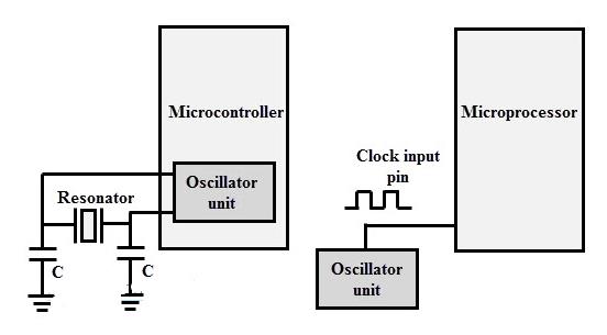
The above figure shows the use of a quartz crystal oscillator for microprocessor clock frequency generation, in the case of a microcontroller, a quartz crystal resonator is sufficient for this job. Depending on the value of the maximum clock frequency that the system can run, the value of the oscillator circuit or crystal is decided.
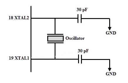
The following figure illustrates the operation of 8051 microcontroller based on external crystal oscillator. Typically, the quartz crystal oscillator is connected between the input pins XTAL1 and XTAL2.
XTAL1 is the input of the inverting oscillator amplifier and the input of the internal clock generation circuit, while XTAL2 is the output of the inverting oscillator amplifier. For the 8052 microcontroller, the most commonly used crystal frequency is
12 MHz and 11.059 MHz, but 11.059 is more common.
- LM337 pin diagram and parameters, LM337 application circuit diagram
- What is the function of a voltage regulator in a circuit? How to connect a voltage regulator?
- Why do we need a MOSFET gate resistor? MOSFET Gate Resistor Placement
- How do Zener diodes protect circuits?
- Principle set of zero-crossing detection circuit advantages and disadvantages
- What are the parts of the fpga design process
- Structural diagram and function of sliding resistor
- Make a simple AM radio with digital circuit
- LED lights that “drain” battery power
- Simple LED advertising light circuit
- Color changing flash light principle circuit diagram
- Power outage sound and light alarm circuit
- crystal controlled oscillatora
- How to connect the load of capacitive three-point oscillatorb
- Colpitts oscillator
- Dual T oscillator
- Siren signal generator circuit
- One of the inductive anti-theft alarm circuits using capacitor oscillator
- Temperature stable oscillator.gif
- 5MHz video oscillator.gif


 京公网安备 11010802033920号