Dual Power Supply Circuit Analysis
Source: InternetPublisher:吃掉星星 Keywords: power supply circuit dual power supply bipolar dual supply voltage Updated: 2025/03/04
Dual power supply circuit (I)
Bipolar or dual voltage power supply can be easily designed with the help of two 3 terminal regulators. The above figure shows the case of LM320 and LM340 using ICs. Out-of-phase AC is provided by the secondary of the transformer and the grounded center tap. A single full wave bridge converts these voltages into positive DC voltage and negative DC voltage (with respect to the grounded center tap). The output of the rectifier circuit is filtered with the help of capacitors C1 and C2.
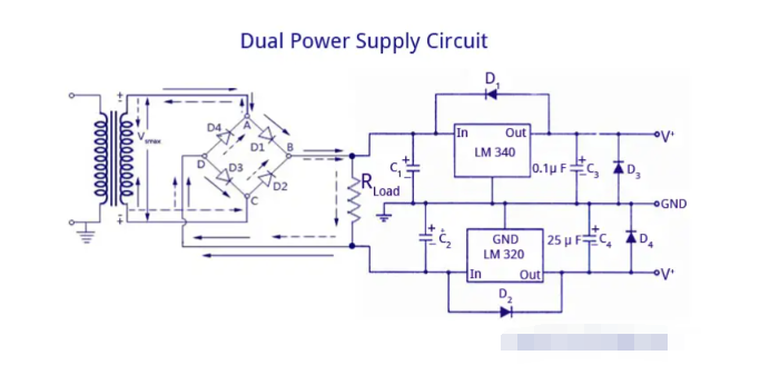
The LM340 provides positive voltage regulation and the LM320 regulates negative voltage. It is also important to note that the two ICs have different pin configurations. The case of the LM320 is not considered ground. Therefore, special care must be taken when installing a negative regulator.
The diodes in the LM circuit are used to provide protection. They ensure that transient voltages at the output of the regulator do not drive the output to a potential higher than its input, causing damage to the regulator. It is important to note that the diodes are placed as shown in the diagram and not the other way around. The diodes also play an important role in turning on both regulators at the same time. If there is a chance that this could happen, the output of the slower regulator could be driven to the potential of the faster regulator. Therefore, the diodes protect against these reverse polarities at startup.
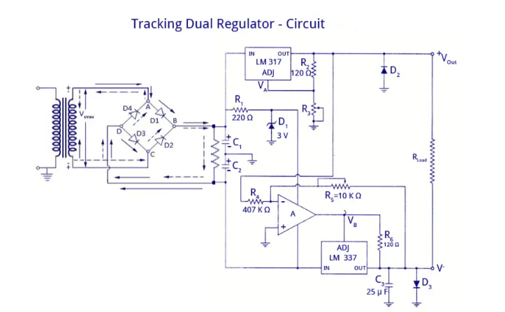
Many applications require several different voltage supplies. One solution is to build several independent regulators. However, it is often important to keep track of all of these supply voltages. That is, if one of the supply voltages goes up by 2%, it would be best if all of them went up by the same amount. This can be accomplished by adding an op amp to the adjustable three-terminal regulator.
The circuit shown in the figure provides current limiting and thermal shutdown functions for both negative and positive output voltages. The positive regulated voltage is generated by the LM317 adjustable positive regulator IC as shown in the figure.
The regulated positive voltage is always 2.3V higher than the voltage across R1 (at the adjust pin). This regulated output voltage is used as the input to an inverting amplifier. Op amp A is the input stage of this amplifier and the LM337 negative regulator is the power output stage. Therefore, the negative regulated output voltage, V" is an amplified and inverted version of the positive regulated voltage, V+. Current limiting and thermal shutdown are provided independently by the LM317 (for the positive output) and the LM337 (for the negative output). The op amp ensures that the negative output voltage tracks the positive output by driving the adjust pin of the LM337 to a voltage +1.2V above the desired negative output. Because the LM337 is inside the negative feedback loop of the op amp, this +1.2V offset appears between the op amp and the regulator, not at the regulator output.
Dual power supply circuit (II)
In everyday electrical appliances, examples of automatic dual power switching can be seen everywhere, such as power switching between AC adapter and USB power supply, and automatic switching between battery power supply and USB power supply.
These circuits all follow a common principle: giving priority to those with higher voltages.
In fact, this circuit was originally discovered in a lithium battery charging circuit. The data sheet very considerately provides a reference application for automatic switching of dual power supplies, which is simple and easy to implement.
Circuit:
Actual circuit phenomenon:
Just plug in the AC adapter and the circuit will automatically switch to powering the AC adapter.
Just plug in the USB-5V power supply, the circuit will automatically switch to USB power supply.
Connect the AC adapter and USB-5V power supply to the circuit at the same time. Since the output voltage of the AC adapter is generally above 5.5V, which is slightly higher than the 5V of the USB power supply, the circuit will automatically switch to the AC adapter for power supply.
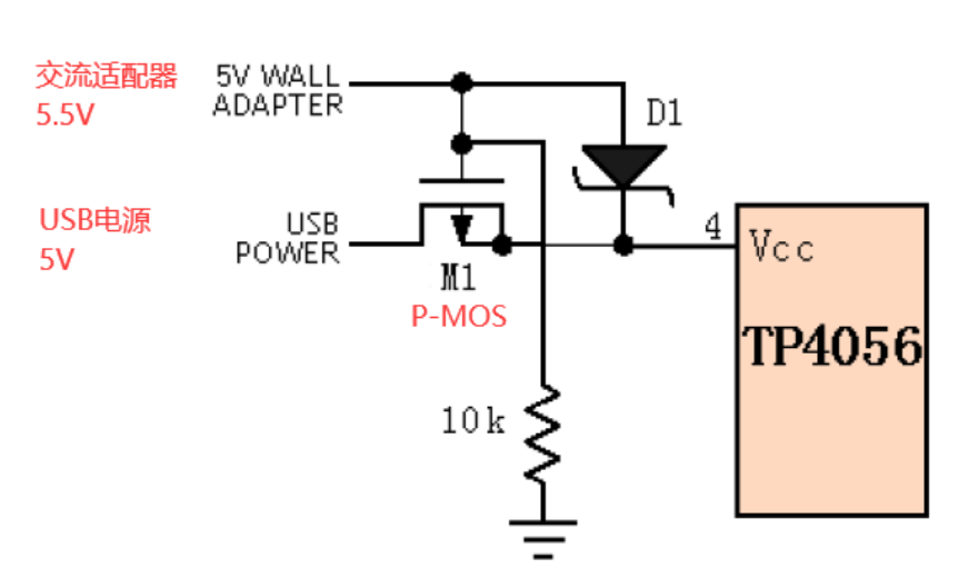
Circuit principle:
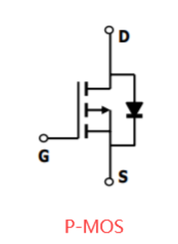
The circuit consists of a P-MOS (such as AO3401), a diode (Schottky is recommended, with small voltage drop), and a pull-down resistor of appropriate resistance.
Assume the USB power voltage is 5.0V, and the voltage of the AC adapter is 5.5V, which is slightly higher than that of USB.
When the 5.5V of the AC adapter is connected alone, the diode is turned on and the circuit automatically switches to power supply by the AC adapter. At this time, the voltage at the power end is 5.5-0.3=5.2V.
When USB-5V is connected alone, the DS parasitic diode of P-MOS is turned on first, and the S pole voltage is 5-0.7=4.3V, and the G pole is pulled down to 0V by the pull-down resistor at this time, so Vgs=0-4.3=-4.3V. -4.3V<the minimum GS turn-on threshold voltage of P-MOS, so P-MOS is turned on, and then the voltage at the power end is 5-I*Ron. Since the turn-on voltage of MOS is relatively low, about tens of mΩ, and the current of the general circuit will not exceed 2A, the turn-on voltage drop of P-MOS can be almost ignored. 5V can be output to the power end very efficiently.
When the AC adapter 5.5V and USB-5V are connected at the same time, Schottky D1 is turned on, and the G pole voltage of P-MOS is 5.5V, the S pole voltage is 5.2V, Vgs=5.5-5.2=0.3V, 0.3V》P-MOS GS minimum conduction threshold voltage, so P-MOS is turned off. The circuit automatically switches to the AC adapter with higher input voltage for power supply.
Similarly, this method is also applicable to the automatic switching between battery input and USB power. Connect the USB power supply to the upper side of the circuit input and the 4.2V lithium battery to the lower side of the circuit input. The circuit will give priority to the one with higher voltage.
- Current source voltage calculation method formula, how to calculate the power of the current source
- TL783 voltage regulator protection circuit diagram
- How to enhance power and signal integrity through low noise?
- What effect does the copper coating on the bottom of the inductor have on the power supply?
- Analysis of the working principle of switching regulator
- How to use a simple circuit to achieve a smooth soft-start for an isolated converter
- Practical and convenient fax machine power supply control circuit
- Brief Analysis of the Working Principle of AC Voltage Stabilizer Circuit
- Recommended circuits for different power on times of LM4911
- Adjustable regulated power supply with current limiting protection
- Importance of Voltage Supervisors and Output Topology Selection
- Portable device charging power circuit design
- Dual adjustable power circuit
- Solar power circuit
- Power circuit with smoothing filter capacitor
- Output 12V-10A power supply circuit
- 2-phase CPU power supply circuit using HIP6302 and HIP6602 chips
- 2-phase CPU power circuit using HIP6302 and HIP6601 chips
- Head amplifier dedicated power supply circuit
- QM-N5 type gas sensor dual power supply application circuit


 京公网安备 11010802033920号