Design ideas and precautions for NTC circuits inside silicon carbide power modules
Source: InternetPublisher:aerobotics Keywords: Temperature sensor NTC power module Updated: 2025/02/25
Most power modules contain an NTC temperature sensor, usually a negative temperature coefficient thermistor, whose resistance decreases as the temperature increases. Because of its low cost, NTC thermistors can be used as devices for power module temperature measurement and over-temperature protection, but other devices such as PTC positive temperature coefficient resistors are more suitable for specific temperature control applications. Using temperature sensor information is relatively easy, but you need to pay attention to safety considerations involved in the system.
1. Overview of NTC thermistor inside the module
The NTC thermistor is placed close to the power die, on the same ceramic substrate, as shown in Figure 1
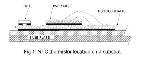
Figure 1 Location of NTC thermistor on substrate
Since the self-heating can be ignored, the NTC thermistor maintains almost the same temperature as the power module's case. At the same time, because the thermal resistance RCS from the power module case to the heat sink is generally very small, the measured temperature is generally
close to the heat sink temperature. NTC thermistors are not usually used to monitor the junction temperature of power modules because they will need to be integrated into the power die instead of the case part here. Instead, the junction temperature can be estimated based on the NTC thermistor temperature and
the thermal resistance from the case to the heat sink, which will be discussed next.
NTC thermistors are very useful because of the following features: as a protection for power systems from system failures due to overheating or overcooling, low cost, more sensitive response than thermocouples, easy to use, not affected by noise, temperature range and power module operating temperature range are closely matched, etc. An NTC thermistor has a time constant of about a few seconds, which means it takes a few seconds to detect a temperature change event inside the power module.
Because of its slow response, NTC thermistors are not suitable for detecting rapid changes in temperature and can only be used to protect systems based on slow temperature changes. NTC thermistors cannot be used for short circuit or overcurrent protection. The response of NTC thermistors is exponential. Despite its nonlinearity, NTC thermistors are still useful for module temperature measurement for the following reasons:
Simple threshold circuits can be used to indicate an overtemperature condition, as discussed next. The exponential response can be handled by analog circuits, or by software based digital control systems.
2. Design method of NTC circuit inside the module
The NTC thermistor used in power modules has the following characteristics, as shown in Figure 2:
The resistors at 1.25C are 22kohm, 50kohm.
2.The curve fitting constants of B25/85 are 3980K and 3952K respectively.
3. The NTC thermistor response equation is as follows, RT is the thermistor resistance, T is the Kelvin temperature, T25 is the Kelvin temperature at 25C, 298.15K.
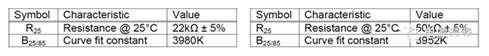
Figure 2 Typical characteristics of NTC thermistors
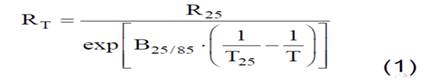
Figure 3 Exponential response equation for NTC thermistor
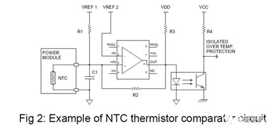
Figure 4 NTC thermistor comparator circuit
NTC thermistors can be easily used in module protection scenarios without calculating the actual thermistor temperature, comparing the voltage across the NTC thermistor with a reference voltage, and stopping the module if it becomes too hot to reduce the risk of module failure. If the NTC thermistor is placed at the lower end of the resistor divider, as shown in Figure 4, as the temperature of the NTC thermistor increases, the voltage at the input comparator decreases from the supply voltage VREF1 to the comparator trigger voltage VREF2.
Assuming that the temperature trigger voltage needs to be set at 100C, the voltage divider at the comparator is set at half of the reference voltage, such as VREF1/2, and the resistor R1 above needs to be set to the same impedance as the NTC at 100C. The thermistor resistance can be calculated using equation 1 in Figure 3 at a given temperature, or obtained by looking up the table. In this example, at 100C, RT=T1=3.43kohm, if the thermistor temperature is below 100C, the comparator output is high, and if the thermistor temperature is above 100C, the comparator output state is low.
The position of the thermistor NTC and R1 can be swapped. In this example, as the temperature increases, the voltage at the input comparator increases from 0V to the trigger voltage VREF2. Regardless of the position of R1 and the NTC thermistor, its time constant and noise immunity are fixed. In practical applications, the comparator needs a hysteresis. Resistors R1 and R2 need to be adjusted to set a certain amount of hysteresis voltage. The hysteresis is based on the output swing of the comparator, which is determined by the parallel connection of R1//RT and the voltage divider of R2. Assuming that the output swing of the comparator is Rail to Rail, as shown in Figure 2, the hysteresis can be calculated.
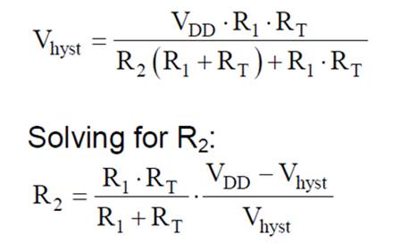
Figure 5 Calculation of comparator hysteresis resistance
In order to increase the noise sensitivity of the NTC thermistor, it is recommended to connect a capacitor in parallel with the resistance of several thousand ohms at the rated temperature. This capacitor is C1 in Figure 4 and must be between 10-100nF. Even with a 100nF decoupling capacitor, the time constant at 25C is only 320 microseconds, which can ensure a very high noise sensitivity and is much lower than the 1000 times of the time constant of the NTC thermistor itself. In most cases, a 10nF decoupling capacitor is a sufficient capacitance value to ensure noise sensitivity.
One thing to note is that regardless of the temperature, the maximum power of the thermistor cannot exceed 20mW to ensure that the temperature measurement is not affected by self-heating.
Solving equation 1, we get the Kelvin temperature, as shown in equation 2,
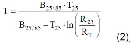
Figure 6 Calculating Kelvin temperature
If we know the values of B25/85 and T25, R25, such as 3952K, 298.15K, 50K, etc., once we determine the value of RT, we can calculate the temperature, referring to Figure 4. The VT voltage is the voltage across the NTC thermistor, and the calculation is shown in Figure 7. This is easy. One temperature corresponds to one RT value, which corresponds to one voltage divider.
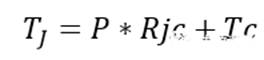
Figure 7 Calculation of thermistor voltage VT
Finally, we can solve for the thermistor resistance, RT, as follows. Note that if R1 has a neutral temperature coefficient, the calculation accuracy will improve. Finally, Equation 4 can be plugged into Equation 2 to calculate the Kelvin temperature of the thermistor.
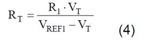
Figure 8 Calculating thermistor resistance
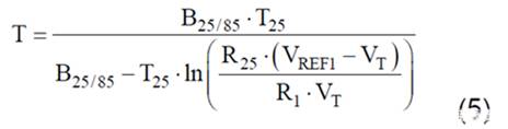
Figure 9 Calculating thermistor temperature
Based on the result of equation 5, the Kelvin temperature can be converted to Celsius by subtracting 273.15. Equation 5 looks quite complicated, but it can be easily solved by the MCU or DSP in the digital control system. Equation 5 can be used to create a table with an excel program and stored in the header file to reduce the running time of the temperature calculation in the digital controller. The NTC thermistor maintains the same temperature as the power module CASE, so the thermistor can be easily used as the power module substrate CASE temperature Tc.
In general, for NTC thermistors, one temperature corresponds to one resistance, and the comparator voltage can be determined based on the resistance. Based on this relationship, the actual measured temperature can be finally deduced.
Knowing the module case temperature Tc, thermal resistance Jc, and power consumption of each die, the temperature of the power module die can be calculated using the following formula:
, Heat sink temperature can be calculated using the following formula,
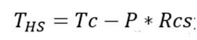
, Since the temperature gets lower as you go out, we can get, where THS is the heat sink temperature, P is the power consumption of the module, and RCS is the thermal resistance from case to heat sink.
Because the thermal resistance RCS from the case to the heat sink of a power module is generally very small, the temperature of the thermistor can be assumed to be close to
the temperature of the heat sink. If appropriate, a correction of -5 to -10C can be subtracted from the temperature measurement to estimate the heat sink temperature. For example, based on a case to heat sink thermal resistance of 0.1C/W, a correction of 10C is required to correspond to a 100W module power dissipation.
3. System safety considerations for using NTC resistors
The generation of plasma gas under extreme conditions causes serious damage to the inside of the module, resulting in damage to the power die. The propagation of plasma gas is unpredictable, and it may contact the NTC thermistor, placing it under dangerous high voltage. Temperature monitoring using NTC thermistors shows that this part of the circuit has the potential risk of being exposed to high voltage, and system designers need to ensure that reliable insulation is provided through appropriate measurements.
Here are some examples to get good insulation:
1.NTC thermistor is used in comparator circuit, which is isolated from control logic by optocoupler. Generally speaking, other protections such as short circuit, overcurrent, overtemperature, etc. are executed based on switch level switching. Fault signals can be superimposed and transmitted through the same optocoupler.
2. The complete system is covered with suitable materials or protective covers.
3. Each application is unique, and designers must take the most effective approach to ensure the safety of system operators.
In summary, the above article briefly analyzes the design ideas and precautions of the NTC circuit inside the silicon carbide power module, which can provide a more comprehensive understanding of the temperature protection characteristics of the silicon carbide power module.
- What is the function of bias resistor? Why do we need bias resistor to transistor?
- What is a photocoupler and how to select and use one?
- What is the difference between MOSFET and BJT? Which one is better between MOSFET and BJT?
- Voltage divider circuit calculation formula, where to find the voltage divider circuit?
- Which one is better, NPN or PNP transistor?
- This article will tell you the hard requirements of operational amplifiers
- The Importance and Ideal Model of Impedance Matching
- Analysis of the working principle of CMOS/CCD image sensor
- Working principle and truth table of JK flip-flop
- Build a musical fountain using Arduino and sound sensor
- 3 and 1/2 digit digital thermometer using diode as temperature sensor
- Motor thermal protection circuit controlled by 3UN2 (with two temperature sensors)
- Simple and practical temperature control circuit
- Positive temperature sensor and coefficient resistor circuit diagram
- Humidity detection circuit diagram of temperature sensor
- Standard line circuit of temperature sensor
- TMP12 air temperature sensor integrated circuit
- KTY84 temperature sensor 5V power supply circuit
- AD22100 type voltage temperature sensor circuit with signal conditioning
- External power interface circuit for digital temperature sensor


 京公网安备 11010802033920号