What is the function of bias resistor? Why do we need bias resistor to transistor?
Source: InternetPublisher:常思一二 Keywords: Transistor amplifier circuit bias resistor Updated: 2025/02/25
In the amplifier circuit, when the transistor works normally, it amplifies the input signal without distortion and has the same signal waveform at the output end. This means that the transistor should work in the amplification area rather than the cutoff area and saturation area.
Therefore, the transistor must have a stable static operating point current, and this current comes from the bias resistor of the transistor. These bias resistors constitute the bias circuit, and the bias circuit provides current to the transistor.
From this we can see that the purpose of adding bias resistors to the transistor is to keep the transistor in an amplification state at all times.
If there is no bias resistor, the transistor will have no bias voltage and will be in the amplification state in the positive half cycle of the signal. In the negative half cycle of the signal, the transistor will have no amplification ability because a negative voltage is added. If you want the transistor to have amplification ability, you need to connect a bias circuit to the power supply to provide it with a bias voltage.
However, connecting a bias resistor cannot provide a suitable bias voltage, nor can it make the bias voltage be in the middle of the amplification state, which is the static working Q point of the transistor. Let the dynamic signal move up and down at the Q point, that is, it does not enter the saturation region or the cut-off region. Therefore, at least two resistors are used to provide a suitable bias voltage.
The most basic bias circuit in the circuit is the fixed bias circuit.
Bias resistor function:
1. Achieve the required operating current/voltage.
2. RC protection circuit, R can also be said to be a bias resistor. Generally speaking, a bias resistor is a resistor that needs to be added to achieve a certain purpose, such as handling voltage and current.
What is the function of adding bias resistor to transistor?
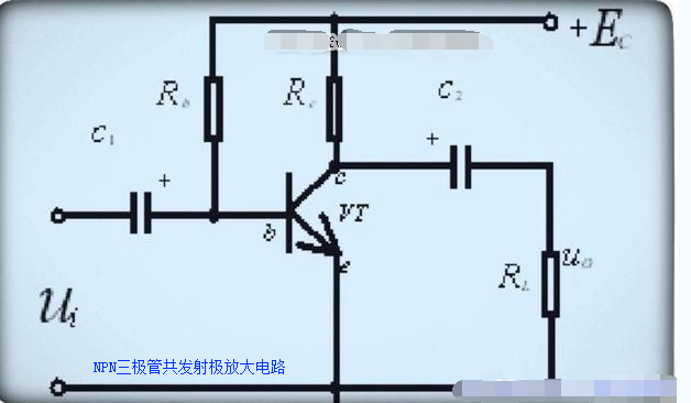
The figure above is a fixed bias circuit diagram using the NPN transistor common emitter amplifier circuit as an example.
Rb in the figure is the bias resistor of the transistor. By adjusting its resistance value, the collector current can be within the design range. In short, adjusting the bias resistor is to adjust the base bias current so that the transistor has a suitable static operating point. In other words, the amplifier composed of transistors has a normal operating voltage. The one in the figure is a fixed bias circuit diagram. The specific value of the bias resistor has been calculated before the circuit design, and there is no need to fine-tune the resistor.
To use an analogy, the bias resistor is equivalent to human food. To be meaningful, people must survive. How much food to eat depends on personal needs, that is, you cannot starve to death or eat too much. In the same way, the transistor must be in the amplification state at all times, which depends on the bias resistor. The specific bias resistor should be determined according to the specific circuit design to ensure that the transistor neither enters the saturation region nor the cutoff region.
- Application and classification of current sensing resistors
- Summary of I2C basics: How does I2C communication actually work?
- What is a photocoupler and how to select and use one?
- How are diodes made using semiconductors?
- What is the difference between single-phase and three-phase power? When is three-phase power required?
- What is the difference between CPLD and FPGA?
- Why Do Amplifier Fuses Blow? How Do You Prevent Amplifier Fuses from Blowing?
- Working principle and truth table of JK flip-flop
- How does RCCB work?
- Why use PWM? What are its advantages?
- Transistor circuit diagram explanation
- Six common constant current source circuit diagrams and analysis
- A single-section transistor performance test circuit
- M50560 infrared transmitter circuit
- Color changing flash light principle circuit diagram
- Three types of transistor amplification circuits and their characteristics - common collector circuit
- One of the water full alarm circuits
- Fuse blown sound and light alarm circuit 4
- Flash signal light circuit 7
- Manual temperature control circuit 5


 京公网安备 11010802033920号