How to convert an inverting amplifier into a summing amplifier?
Source: InternetPublisher:newrudeman Keywords: Amplifier Inverting Amplifier Operational Amplifier Updated: 2025/02/18
As we know, an operational amplifier is a type of power amplifier. However, an operational amplifier can also perform a summing operation. In this article, we share an operational amplifier circuit that can combine multiple input signals and produce a single output as the weighted sum of the input signals.
What is a Summing Amplifier? A summing amplifier is also an operational amplifier circuit that can combine multiple input signals into a single output that is a weighted sum of the applied inputs.
What is a summing amplifier? A summing amplifier is a variation of an inverting amplifier. In an inverting amplifier, only a voltage signal is applied to the inverting input as shown below:
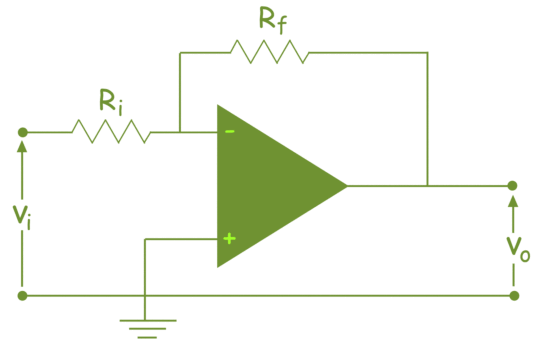
This simple inverting amplifier can be easily modified into a summing amplifier if we connect multiple input terminals in parallel to the existing input terminals, as shown below:
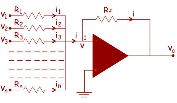
Here, n input terminals are connected in parallel. Here, in the circuit, the non-inverting terminal of the operational amplifier is grounded, so the potential of this terminal is zero. Since the operational amplifier is considered to be an ideal operational amplifier, the potential of the inverting terminal is also zero.
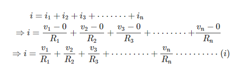
Therefore, the potential at node 1 is also zero. It is also clear from the circuit that the current i is the sum of the currents at the input terminals.
Therefore, we can conclude that:
Now, in case of an ideal op-amp, the current in both the inverting and non-inverting terminals is zero. So, according to Kirchhoff’s current law, the entire input current goes through the feedback path of resistor Rf. That is:
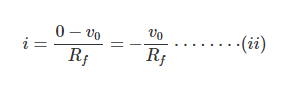
From equations (i) and (ii), we obtain:
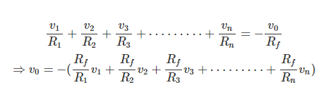
This shows that the output voltage V0 is a weighted sum of the input voltage quantities.
Here, we take an adder example. We first calculate the output voltage of the three summing amplifiers, and the circuit is shown in the figure below:
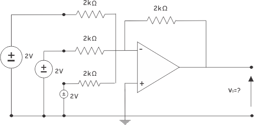
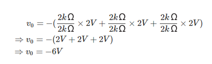
Here, from the equation for the summing amplifier, we have:
- Differential amplifier formula, Wheatstone bridge differential amplifier circuit analysis
- How to judge the design quality of printed circuit boards?
- Types and specifications of optocoupler ICs
- Why Use LED Drivers? Tips for Selecting LED Driver ICs
- Does lithium iron phosphate battery need a protection board? The correct way to charge lithium iron phosphate battery
- What is a Half Wave Rectifier? Working Principle of a Half Wave Rectifier
- An article explains the working principle of the Wheatstone bridge
- In-depth analysis of energy losses in oscillation frequencies
- What are the classifications of filters?
- Simple Wired Spy Bug Circuit Built Based on IC741
- High performance broadband GaN power amplifier
- Two-channel audio power amplifier circuit diagram analysis
- High-precision low-noise filter circuit design
- Cascade MMIC amplifier circuit diagram
- High input impedance three op amp differential amplifier circuit diagram
- Differential bridge amplifier circuit diagram
- Operational transconductance amplifier with booster
- Differential bridge amplifier circuit diagram
- variable gain amplifier
- Compact Unity Gain Inverting Amplifier Circuit


 京公网安备 11010802033920号