Why Use LED Drivers? Tips for Selecting LED Driver ICs
Source: InternetPublisher:明天见 Keywords: led led driver Updated: 2025/02/18
For high-power LEDs, including white LEDs, these lighting systems require more complex regulation to ensure that the current and voltage on each LED in the system are stable. Although it is possible to build a voltage regulator with some external electronic components, it is much easier to control the system using an LED driver IC. According to microcontroller development engineers, these chips are specifically designed to provide high-efficiency DC power to LEDs.
1. Why use LED drivers?
We can think of the LED driver IC as a power regulator integrated on a chip, which is specially designed to regulate current or voltage to provide a constant voltage or current for high-power LEDs. For high-power lighting systems, an LED driver IC can be used to control the LED power output, which converts the high input voltage into a lower DC level.
According to the MCU development engineer, the brightness of the LED can be adjusted by adjusting the output power of the LED driver IC. High-power LED driver ICs are usually soldered on the surface of the PCB board to dissipate heat into the substrate. For dimming control, some LED driver ICs can be programmed internally through the I/O port, while other LED drivers use PWM dimming on the MOSFET driver to control the power output (similar to a switching regulator).
2. How to use PWM of microcontroller for dimming?
According to the MCU development engineer, the common method to adjust the brightness of a string of LEDs is to use the PWM signal of the MCU. Here is an example of how to use MCU for PWM dimming. As shown in the figure below, the 50
The kOhm resistor creates a feedback loop that provides a high voltage/current output to the downstream LED. Note that in this arrangement, a parallel circuit is used to drive the white LED, although a series implementation is common. We can use a microcontroller (MCU) to control the power output by adjusting the PWM duty cycle. The size of the duty cycle can be based on sensor readings (such as a temperature sensor) or using some input from the user.
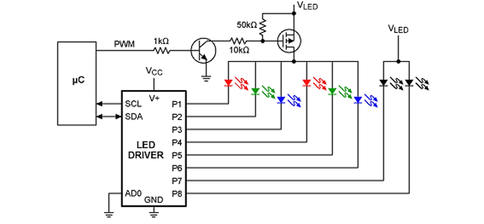
In this example, the LED driver acts like a shunt current regulator, and the PWM signal and MOSFET drive the LED switch near the forward voltage at the switching frequency. The average power is then linearly proportional to the duty cycle of the PWM signal. A high power current limiting resistor can also be added to each leg to prevent overdriving during switching.
The advantage in this case is that the designer can program multiple power settings into the MCU. Using a simple 8-bit MCU, multiple PWM settings can be stored in the EEPROM and the user can switch between them with a button.
Once you have decided how best to regulate the output power and provide dimming, the next step is to select an LED driver IC to deliver the required power to the lighting system.
3. Tips for selecting LED driver IC
LED drivers have many features that mimic those of standard power regulators, but they may include additional features such as programmability, current sense feedback for regulation, and temperature sensing. For high-power LED driver ICs, there are several important specifications to consider:
1. Output voltage and current. In order for the LED to light up, the output power must be equal to or higher than the forward voltage and forward current of the diode. Some LED drivers act like buck or boost converters, which output at a specific current at a DC voltage equal to or higher than the forward voltage, thus providing the required power output.
2. Series vs. parallel outputs. Smaller LED drivers may only have a single output at high voltage and fixed current, allowing a string of LEDs to be driven in series. LED driver ICs with multiple outputs are often used in parallel.
3. Integration with external PWM (using a microcontroller). Some LED drivers contain a PWM generator and provide the signal directly to the MOSFET.
4. Power efficiency. For high-power systems, this is a very important point because it determines the power lost as heat.
For LED series and parallel outputs, you can output to multiple LED lines in parallel, where each line contains multiple LED lines in series. Pay attention to the total forward voltage and current of the output, as this will determine how many series or parallel strands you can use in your lighting system.
- TL783 parameters/pin configuration and functions, tl783 parameter circuit diagram
- How to judge the design quality of printed circuit boards?
- RISC structure and its advantages and disadvantages
- Principle set of zero-crossing detection circuit advantages and disadvantages
- What are the main types of resistors? Detailed explanation of the functions and uses of resistors
- What are the types of commonly used batteries?
- What is power factor and three ways to improve it
- Working principle/characteristics/application fields/equivalent circuit of unijunction transistor
- Causes of PCB deformation How to prevent circuit board bending and warping
- How does RCCB work?
- MAX8631X driving white LED circuit diagram
- 3×8 LED drive circuit diagram with overvoltage protection function
- Practical circuit diagram of an LED lamp cup
- LED driver circuit diagram powered by solar cells
- LED backlight driver module design circuit
- High battery life LED circuit based on GEC8310
- LED level meter driver integrated circuit diagram
- Fish farming thermostatic control circuit
- Quiz quizzes circuit
- Paper thickness measurement circuit


 京公网安备 11010802033920号