Feedback Amplifiers
Source: InternetPublisher:酷到被通缉 Keywords: Amplifier Feedback Amplifier Updated: 2025/02/18
Feedback amplifiers are a type of amplifier that is connected so that the output is fed back to the input. Microcontroller development engineers say that amplifiers are devices that increase signal strength, but the increase in signal strength also introduces noise into the system.
Because as long as the operation is performed, noise will be generated. This noise will affect the system, so we can avoid this situation by applying feedback to the system. Generally, there are many types of feedback amplifiers, and most of them are designed according to the requirements of various factors.
1. What is a feedback amplifier?
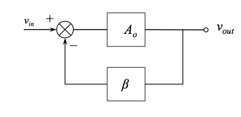
Definition: An amplifier in which a feedback connection is established between the output to the input is called a feedback amplifier. There is a feedback factor between the generated feedback signal and the applied input signal. Whereas, in an amplifier, the output signal is generated due to the applied input signal which is in turn provided as feedback to the input signal, this is called a feedback amplifier.
Types of Feedback Amplifiers
Feedback amplifiers are designed in such a way that the output is fed back to the input, which minimizes the noise generated in the circuit due to the operations it performs. Broadly, feedback amplifiers can be divided into two types:
(1) Positive feedback amplifier
The feedback applied to the input increases the input signal which can be a voltage signal. This is called the positive type. It is also known as a direct amplifier. But these amplifiers cannot amplify very well, but they are used in various types of oscillators.
(2) Negative feedback amplifier
The feedback signal applied to the amplifier if its input signal is reduced due to its application. The input applied can be a voltage or current signal. This type of feedback is called the negation type. It is also known as an inverting amplifier. In this case, the noise generated in the circuit is reduced. Therefore, it is most widely used for signal amplification.
3. Feedback Amplifier Classification
In feedback amplification of a signal, either a voltage or a current signal can be applied at the input of the amplifier. Hence, topologies known for their series and parallel properties are applied for both voltage and current signals. Hence, the four topologies of these amplifiers are as follows:
(1) Voltage type
In this type of amplifier, the feedback in the circuit is designed so that the output signal applied to the input is in series. The feedback circuit of the output signal is in parallel so that the minimum output impedance is observed. The feedback circuit is in series with the input signal so that the impedance of this stage can be increased.
(3) Voltage shunt
In this type, the voltage signal generated at the output is fed back to the input through a feedback circuit. But in this case, the feedback circuit is connected in parallel with the input. In this case, both the input and the output are connected in parallel with the feedback circuit. Therefore, on both sides, the impedance value is maintained low.
(4) Current type
In this type of feedback amplification of the signal, a portion of the output signal fed back to the input signal is connected in series with the feedback circuit. Since a series connection is established between the output and input signals related to the feedback circuit, the impedance values on both sides are high.
(5) Current shunt
A feedback circuit that is connected in series for the output and in parallel with the input signal is called a current shunt feedback amplifier. The impedance value is very low due to the parallel connection with the input. The output connected in series will make the impedance value higher.
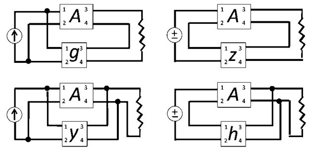
These are the four topologies of feedback amplifiers for voltage or current signals.
4. Feedback Amplifier Characteristics
Of the two types of amplifiers, the most widely used amplifier is the negative feedback amplifier. The characteristics of this amplifier are:
1. In the topology of the feedback amplifier with voltage series feedback, the input impedance value increases while the output impedance decreases.
2. In the voltage shunt feedback topology, both the input and output resistance values are reduced.
3. In the current series feedback circuit, due to its topological structure, both the input and output resistances are increased.
4. In the current shunt feedback topology, the input resistance of the amplifier is reduced and the output resistance is reduced due to the connectivity of the amplifier's input, output, and feedback circuits.
5. In this way, features are defined based on various topologies. Each topology defined has its own usage meaning.
5. Application of Feedback Amplifier
Positive feedback amplifiers are good at obtaining gain values but can cause signal distortion. Therefore, they are not a good choice during amplification. However, negative feedback has the property of minimizing the noise level of the system. The applications of negative feedback are as follows:
1. In a regulated power supply (RPS), it is very suitable for feedback amplifiers.
2. These feedback amplifiers require the use of amplifiers with large bandwidth.
3. It can be used in various amplifier designs in the electronics field.
In summary, feedback amplifiers have two basic types: positive and negative, but in signal amplification, negative feedback is better than positive feedback.
- Differential amplifier formula, Wheatstone bridge differential amplifier circuit analysis
- Feedback Amplifiers
- How to choose the right operational amplifier chip?
- Analysis of Operational Amplifier Differentiator Circuit
- The unidirectional conduction current of the diode, the diode and its common uses
- Which one is better, NPN or PNP transistor?
- What is an ac to dc transformer in circuit design
- What types of power field effect tubes are there? Selection criteria for power field effect tubes
- What are the classifications of filters?
- Causes of PCB deformation How to prevent circuit board bending and warping
- Heart rate detection circuit
- Single Supply Op Amp Applications
- 90V/10A high power amplifier
- TDA2030A subwoofer circuit diagram
- Sense amplifier circuit
- Clamp amplifier circuit diagram
- A crystal controlled local oscillator circuit diagram
- Adjustable output voltage regulator circuit diagram
- non-diode rectifier
- Two common-emitter transistor amplifiers connected to form a directly coupled two-stage amplifier


 京公网安备 11010802033920号