How to choose the right operational amplifier chip?
Source: InternetPublisher:aerobotics Keywords: Operational amplifier electronic circuit Updated: 2025/02/18
One of the most important functions of electronic circuits is amplification, without which many other specific circuits would not work. For example, an oscillator that produces a sine wave, square wave, pulse, or any other desired waveform would not be possible without an amplifier circuit.
Operational amplifiers can achieve very high performance and highly stable amplification circuits using very few passive components, so in this article, microcontroller development engineers will introduce what operational amplifiers are and how to choose operational amplifiers.
1. What is an operational amplifier?
If we imagine a perfect amplifier it should have infinite gain, infinite input impedance, zero output impedance and infinite bandwidth but in real life nothing is ideal so they have finite gain and finite bandwidth.
The term operational amplifier was originally used for DC amplifiers that performed mathematical operations such as summation, subtraction, integration, and differentiation in analog computers. Operational amplifiers are much broader in scope and can be used in a variety of other applications besides amplification, such as voltage regulators in instrumentation and control systems.
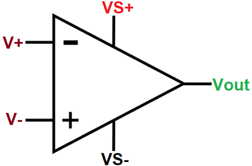
An operational amplifier can amplify signals with a frequency range of 0 Hz to 1 MHz. This means that an OP-AMP can be used to amplify DC signals (0
Hz) and AC input signal (high frequency signal). Moreover, it is designed in such a way that external components like resistors, capacitors, etc. can be connected to its terminals. By adding these passive components, its external characteristics can be changed.
2. Understanding operational amplifier parameters
When designing a product, it is essential to understand the characteristics of an operational amplifier, i.e., if you want to design a product efficiently and minimize the cost, then you should understand the following parameters of an operational amplifier:
1. Open-loop voltage gain: The most important function of an amplifier is to amplify the signal. Every amplifier has a certain gain, which means that if an input voltage is applied, it will be multiplied by the gain. For example, if the gain of an operational amplifier is 2*
10^5, with a 2 V input, the output voltage would be 400000 V, which is actually impossible because it would mean the op amp is saturated and the output voltage is limited to VCC.
2. Input Resistance: It is the resistance between the non-inverting and inverting inputs of the amplifier.
3. Output Resistance: The output resistance is like the internal resistance of the battery, so it is a very small resistance, which means that the output voltage depends on the load.
4. Input offset voltage: If we apply the same input voltage to both terminals of the op amp, the output should be zero volts. In reality, this is not possible because the transistors inside do not have the same value, so a small voltage will appear at the output. Therefore, to make the output zero, we must apply a small differential voltage, which is called the input offset voltage.
5. Input offset current: If we ground both the non-inverting and inverting terminals of the operational amplifier, we can see that a very small current will flow through the output pin of the operational amplifier. This is the current generated due to the unequal base currents of the internal transistors. Therefore, in order to make the output current zero, a small input current can be applied to offset the output current. This input current is called input offset current.
6. Input bias current: The input bias current is the average value of the current flowing into the inverting and non-inverting input terminals of the operational amplifier. The smaller the input bias current, the smaller the drift.
7. CMRR: Common-mode rejection ratio (CMRR) is defined as the ratio of the differential voltage gain to the common-mode voltage gain. The ability of a differential amplifier to reject common-mode signals is expressed by the common-mode rejection ratio.
8. Slope: It is defined as the maximum rate of change of output voltage per unit time, expressed in volts/microsecond.
The slew rate indicates how fast the output of the OP-AMP can change in response to changes in the input frequency 9. Voltage Swing: It is defined as how close the output voltage can get to the supply voltage or how well the output can be driven rail to rail.
10. Gain Bandwidth Product: As we know, the voltage gain of an operational amplifier decreases at high frequencies due to storage caused by parasitic junction capacitance and minority carrier changes in the device. As the frequency input signal increases, the open loop gain decreases until it eventually reacts to a value of 1. The frequency at which the gain decreases to 1 is defined as the unity gain frequency or unity gain bandwidth.
11. Peak-to-peak input noise voltage: If we look at a noise signal, it will have a maximum point and a minimum point, the difference between the minimum and maximum is called the peak-to-peak input noise voltage.
12. Unity Gain: A unity gain amplifier is an amplifier with a gain of 1, which also means no gain. The output voltage will be the same as the input voltage and is often called a voltage follower amplifier.
- RISC structure and its advantages and disadvantages
- Characteristics, advantages and disadvantages of CISC architecture
- Why Use LED Drivers? Tips for Selecting LED Driver ICs
- What is a FinFET? What are the advantages and disadvantages of FinFET?
- Symbol/working principle/type/characteristics/application scenarios of depletion-mode MOSFET
- What is an ac to dc transformer in circuit design
- Ideal characteristics of operational amplifiers/pin configurations/gain types/primary applications
- Analysis of the working principle of CMOS/CCD image sensor
- Working principle and truth table of JK flip-flop
- How to build a drag racing timer circuit using a 7-segment display and discrete components
- Light trigger switch circuit
- Practical amplifier circuit consisting of operational amplifier LM386 e
- Low output impedance operational amplifier circuit
- Practical amplifier circuit c composed of operational amplifier LM386
- Low Q Gain Band Pass Filter Amplifier
- Typical circuit of three-terminal fixed stabilizerb
- Op Amp Stabilized Power Supply Circuit Part 5
- A connection circuit using only 5V power supply
- Interface circuit between operational amplifier and COMS
- Single potentiometer gain-adjustable op amp


 京公网安备 11010802033920号