What is an ac to dc transformer in circuit design
Source: InternetPublisher:兰博 Keywords: Circuit design transformer Updated: 2025/01/24
What is an AC to DC transformer? A transformer is a component consisting of a common iron core with at least two windings around it. A transformer uses the principle of electromagnetic induction to step down or step up the AC voltage.
When an AC voltage is applied to the primary winding, energy is stored in the core and coupled to the secondary winding. Depending on the turns ratio, the secondary winding will produce an AC voltage accordingly. A step-down transformer will have more primary windings, while a step-up transformer will have the opposite.
An AC to DC transformer is a transformer connected to an AC rectifier circuit that converts the AC voltage to a DC voltage after stepping up or down the AC voltage. An AC to DC transformer is a simple solution for powering electronic devices from an AC power source. Usually, we find that most adapters that plug into power outlets are AC to DC transformers.
1. AC/DC transformer design
To assemble an AC to DC transformer, you first need to select a transformer with the correct winding ratio. The following formula can be used:
Primary voltage/secondary voltage = primary turns/secondary turns
Next, consider the transformer's material and size, as these may affect its current rating. Choose a transformer that can reliably convert energy for the load in your circuit.
The key to designing an AC-DC transformer lies in its rectification circuit. You will have two types of circuits to choose from - half-wave or full-wave rectification.
Half-wave rectification involves placing a single diode in series with the secondary winding. The result is that only the positive cycle of the AC voltage is allowed to pass.
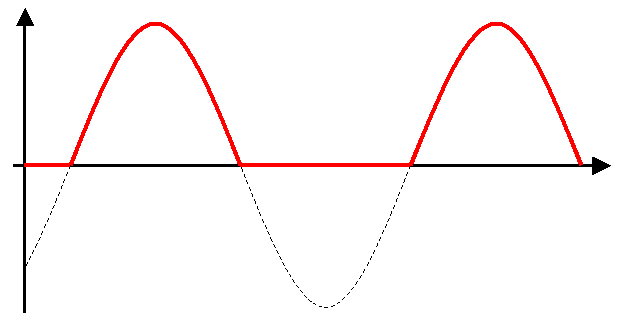
At the output of a half-wave rectifier, only the positive cycle of the AC voltage can pass.
A large capacitor is placed across the secondary output to even out the waveform, producing the desired DC output. However, half-wave rectification is not very efficient - it is difficult to smooth out such an uneven output.
Full wave rectification is a better option for converting AC voltage to DC voltage. This method involves connecting the secondary AC output to a full wave diode bridge rectifier. The full wave rectifier does not just chop the negative cycles but flips the negative cycles to positive cycles.
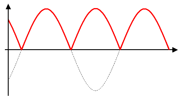
The output of a full-wave rectifier is a better alternative for converting AC voltage to DC because it converts negative cycles into positive cycles.
Obviously, choosing full-wave rectification is the better choice. At the expense of four diodes, you get a less choppy DC output, which means a lower value capacitor can be used to smooth out the peaks. Full-wave rectification is also more efficient because the energy from the negative cycle is converted and transferred to the load.
2. Limitations of AC to DC Transformers
Despite their simplicity, AC to DC transformers have limitations. First, the DC voltage output is susceptible to fluctuations in the primary input. Therefore, it is never a good idea to connect a microcontroller or IC directly to an AC to DC transformer.
AC to DC transformers are also inefficient, as most of the energy is dissipated as heat. Transformers are also expensive and take up too much space in a design. Still, when manufactured in bulk, AC to DC transformers remain an economical, versatile solution.
- What is the difference between MOSFET and BJT? Which one is better between MOSFET and BJT?
- Why do we need a MOSFET gate resistor? MOSFET Gate Resistor Placement
- Symbol/working principle/type/characteristics/application scenarios of depletion-mode MOSFET
- How to identify common mode interference? Methods to eliminate common mode interference
- The Importance and Ideal Model of Impedance Matching
- Basic characteristics/working principles and application circuits of tunnel diodes
- Share an interesting LED decoration project
- How to build a drag racing timer circuit using a 7-segment display and discrete components
- How to build a triangle wave generator using an op amp and discrete components
- Tutorial on building a NOT gate using BJT transistors
- How to design a forward switching power supply?
- Neon flash circuit (2)
- A circuit diagram of a household inverter power supply with excellent performance
- Comparison of LC Oscillators – Transformer Feedback Oscillators
- Push-pull power amplifier circuit
- Simple buzzer circuit three
- Rectifier circuit for bipolar voltage output from double-winding transformer b
- Applications to change output voltage polarity (a)
- latch storage circuit
- The synchronous voltage is taken out from the secondary side of the two-phase transformer


 京公网安备 11010802033920号