Analysis of circuit design of MCU controlled relay
Source: InternetPublisher:失踪的猫 Keywords: relay mcu circuit design Updated: 2025/01/24
Two ways to control relays
Controlling the relay to open and close is nothing more than controlling the on and off of the power supply or ground terminal of the relay. It is usually achieved by using a triode switch or a field effect transistor switch. Regardless of the solution, the idea is the same. The following will analyze the idea of relay circuit design in terms of controlling the on and off of the power supply and the on and off of the ground using actual product circuits.
1. Control power on and off
The circuit in the figure below is a 12V relay control circuit of a device, which is used to control the on and off of the vehicle's oil circuit.
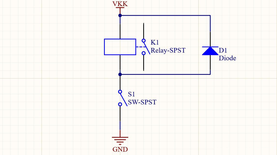
Wiring diagram:

Schematic diagram:
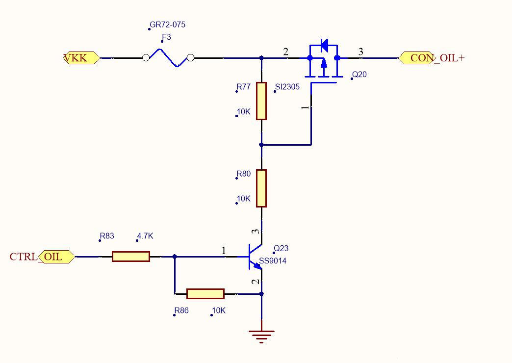
Let's analyze the circuit briefly:
VKK is the main power supply, CON_OIL+ is connected to one end of the relay coil, the other end of the relay coil is grounded, and CTRL_OIL is the MCU control pin.
CTRL_OIL ==》 Low level
When CTRL_OIL is set to low level, transistor Q23 is not turned on and the G of PMOS tube Q20 is
The pole is pulled high by resistor R77 and is not turned on, so no current flows through the relay and the relay is in the disconnected state.
CTRL_OIL ==》 High level
When CTRL_OIL is set to a high level, transistor Q23 is turned on, the G pole of PMOS tube Q20 is pulled down to 1/2 VKK, VGS < 0, PMOS tube Q20 is turned on, current flows through the relay coil, and the relay is in a closed state.
2. Control grounding on and off
The circuit in the figure below is a 12V relay control circuit of another device. The difference from the figure above is that this one controls the on and off of the relay ground terminal.
Wiring diagram:
Schematic diagram:
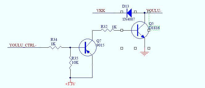
Let's analyze the circuit briefly:
VKK is the main power supply, one end of the relay coil is connected to the power supply, YOULU- is connected to one end of the relay coil, and YOULU_CTRL- is the MCU control pin.
YOULU_CTRL-==》 Low level
When CTRL_OIL is set to a low level, transistor Q7 is turned on, transistor Q5 is turned on, current flows through the relay, and the relay is in a closed state.
YOULU_CTRL- ==》 High level
When CTRL_OIL is set to a high level, transistors Q7 and Q5 are not turned on, no current flows through the relay coil, and the relay is in an open state.
The diode connected in parallel to the relay is called a freewheeling diode, which is used to eliminate the influence of the reverse electromotive force generated when the relay is disconnected on the circuit. When using a freewheeling diode, when the current of the inductive load changes or decreases suddenly, its current can change more smoothly, avoiding the generation of sudden voltage.
This schematic uses 1N4007, a general-purpose diode, which is generally used for rectification. The unidirectional conductivity of this ordinary diode depends on the PN junction formed by the contact between the P-type semiconductor and the N-type semiconductor. Due to the existence of junction capacitance, the reaction time is not too short, so at the moment the switch circuit is disconnected, the ordinary diode may not have time to turn on, which is equivalent to not using a freewheeling diode. It will still generate a large reverse electromotive force, so it would be better to use a Schottky diode.
- How to use 8051 microcontroller to control stepper motor?
- What is the difference between a microcontroller and a microprocessor?
- Make an Interactive Arcade Bedside Clock
- Temperature and clock display
- Interface circuit between MMA1220D and microcontroller
- How to use ESP8266 to make a mini fully functional clock
- Serial debugger circuit implemented with several discrete components
- USB-serial port conversion circuit made with CP2102 chip
- p4 478 chip pin distribution diagram
- A safe and reliable IC card reader/writer system circuit
- Elevator lighting circuit
- High-rise residential walkway lighting control circuit
- Relay fixed time overcurrent protection circuit a
- Relay protection circuitb
- Water inlet motor protection circuit
- Automatic periodic switching circuit three
- Relay power saving circuit 6b
- Relay power saving circuit 4b
- Relay power saving circuit 4a
- Temperature and humidity alarm circuit


 京公网安备 11010802033920号