Home appliance remote control
Source: InternetPublisher:9vHMYp7qu Keywords: remote control Updated: 2026/03/24
Home appliance remote control
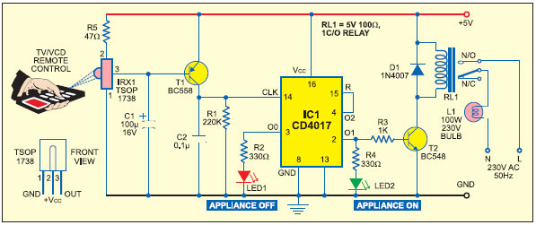
Connect this circuit to any of your home appliances (lights, fans, radios, etc.) to turn them on/off using a TV, VCD, or DVD remote. The circuit can be activated within a range of up to 10 meters. The 38kHz infrared light generated by the remote control is received by the circuit's infrared receiver module, TSOP1738. Pin 1 of the TSOP1738 is connected to ground, pin 2 is connected to the power supply via resistor R5, and the output is taken from pin 3. The output signal is amplified by transistor T1 (BC558). The amplified signal is fed to clock pin 14 of the decimal counter IC CD4017 (IC1). Pin 8 of IC1 is grounded, pin 16 is connected to Vcc, and pin 3 is connected to LED1 (red). When LED1 illuminates, it indicates that the appliance is in the "off" state.
- Universal RC5/RC6 transceiver
- Infrared RC5 remote control transmitter
- PIC-based infrared/radio remote control transceiver
- PIC Infrared/RF Remote Control
- Light remote control switch circuit
- Dual motor wireless remote control circuit production
- Design and production of power carrier remote control alarm circuit
- Color TV remote control 11
- AN5265 sound circuit
- hospital bed pager
- Simple and practical remote control detector circuit diagram
- Remote control circuit diagram composed of CSJ-T300B and CSJ-R02B
- PC remote control circuit
- Remote control coded infrared transmitter circuit
- Dimming remote control circuit
- Remote control receiver circuit
- Photoelectric conversion remote control circuit of glass bottle counter
- BX2-700, 1000, 2000 arc welding machine remote control circuit wiring
- BA5104/BA8206 audio remote control circuit diagram
- Centralized remote control circuit for motor shaft cluster


 京公网安备 11010802033920号