H-bridge drive circuit principle
Source: InternetPublisher:萌面大虾 Keywords: H-bridge driver Updated: 2025/08/01
1. H-bridge drive circuit
Figure 4.12 shows a typical DC motor control circuit. The circuit gets its name from the letter H because its shape resembles the letter H. Four transistors form the four vertical legs of the H, and the motor is the horizontal bar within the H. (Note: Figure 4.12 and the two following figures are schematic diagrams, not complete circuit diagrams; the transistor drive circuit is not shown.)
As shown in the figure, an H-bridge motor drive circuit consists of four transistors and a motor. To operate the motor, a diagonal pair of transistors must be turned on. Depending on the conduction status of each transistor pair, current can flow from left to right or right to left through the motor, thereby controlling the motor's direction of rotation.
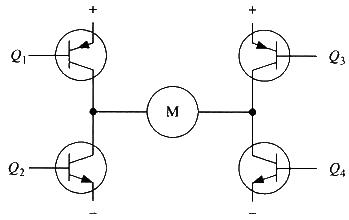
Figure 4.12 H-bridge drive circuit
To rotate the motor, the diagonal pair of transistors must be conducting. For example, as shown in Figure 4.13, when transistors Q1 and Q4 are conducting, current flows from the positive terminal of the power supply through Q1 from left to right through the motor, and then back through Q4 to the negative terminal of the power supply. As indicated by the current arrows in the figure, this current flow will drive the motor to rotate clockwise. When transistors Q1 and Q4 are conducting, current flows from left to right through the motor, driving the motor to rotate in a specific direction (the arrow surrounding the motor indicates a clockwise direction).
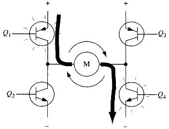
Figure 4.13 H-bridge circuit drives the motor to rotate clockwise
Figure 4.14 shows the other pair of transistors, Q2 and Q3, conducting. Current flows through the motor from right to left. When transistors Q2 and Q3 are conducting, current flows through the motor from right to left, driving the motor in the other direction (the arrows around the motor indicate counterclockwise rotation).
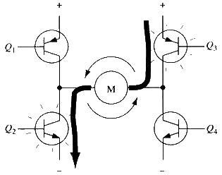
Figure 4.14 H-bridge drives the motor to rotate counterclockwise
2. Enable Control and Direction Logic
When driving a motor, it's crucial to ensure that both transistors on the same side of the H-bridge are not conducting simultaneously. If both transistors Q1 and Q2 are conducting simultaneously, current will flow directly from the positive terminal through both transistors and back to the negative terminal. In this situation, with no load other than the transistors, the current in the circuit could reach its maximum value (limited only by the power supply), potentially damaging the transistors. For this reason, practical drive circuits often utilize hardware to conveniently control the switching of the transistors.
Figure 4.155 shows an improved circuit based on this consideration. It adds four AND gates and two NOT gates to the basic H-bridge circuit. The four AND gates are connected to a single "enable" signal, allowing this single signal to control the entire circuit. The two NOT gates, by providing a directional input, ensure that only one transistor on the same leg of the H-bridge is conducting at any given time. (As with the previous diagrams in this section, Figure 4.15 is not a complete circuit diagram. In particular, directly connecting the AND gates to the transistors will not work properly.)
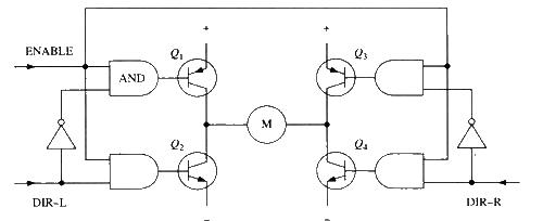
Figure 4.15 H-bridge circuit with enable control and direction logic
Using the above method, the motor's operation only requires three signals: two direction signals and an enable signal. If the DIR-L signal is 0, the DIR-R signal is 1, and the enable signal is 1, transistors Q1 and Q4 conduct, and current flows through the motor from left to right (as shown in Figure 4.16). If the DIR-L signal changes to 1 and the DIR-R signal changes to 0, Q2 and Q3 conduct, and current flows through the motor in the opposite direction.
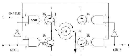
Figure 4.16 Use of enable signal and direction signal
In practice, it's very troublesome to make an H-bridge using discrete components. Fortunately, there are many packaged H-bridge integrated circuits on the market. They can be used by simply connecting a power supply, motor, and control signals. They are very convenient and reliable to use within the rated voltage and current. Commonly used H-bridge integrated circuits include the L293D, L298N, TA7257P, and SN754410.
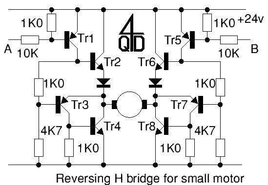
Attached are two pictures of H-bridge driver circuits with discrete components: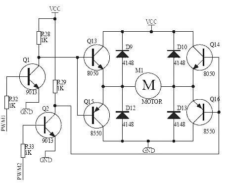
- TDA1010 9W Power Amplifier
- MOSFET amplifier
- 12V lamp current indicator
- The Dangers of Deep Rebound ESD Circuit Protection Diodes
- Diode and gate circuit schematic diagram and principle analysis
- Using diodes to make a capacitor charging and discharging experimental circuit
- Numeric Comparator Basics
- Application of JK flip-flop and T flip-flop
- Driving circuit of TDA485X and TDA4841PS
- Calculating the Input Impedance of a Differential Amplifier
- H-bridge drive circuit working in two quadrants
- 555 square wave oscillation circuit
- 555 photo exposure timer circuit diagram
- Introducing the CD4013 washing machine timer circuit diagram
- Simple level conversion circuit diagram
- 555 electronic guide speaker circuit diagram for blind people
- Circuit diagram of disconnection alarm composed of 555
- Analog circuit corrector circuit diagram
- color discrimination circuit
- Color sensor amplification circuit


 京公网安备 11010802033920号