8-way buzzer composed of CD4508
Source: InternetPublisher:D先生 Keywords: buzzer Updated: 2025/08/12
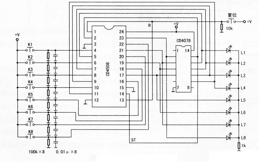
The specific circuit of the 8-channel buzzer made with CD4508 is shown in the figure below.
How it works
When one of the buttons K1 to K8 (such as K3) is connected first, that is, the (8) pin of CD4508 is at a high level "1", the data is transmitted to the (9) pin, which is at a high level "1". After passing through the 8-input NOR gate/OR gate CD4078, its (13) pin outputs a low level "0" and sends it to the latch terminals (2) and (14) (ST1 and ST2) of CD4508. Therefore, the output data is latched, and the other buttons are invalid. At this time, the corresponding indicator light L3 is lit at the same time, and the answer is successful.
Press the reset button, the output data will be cleared, the indicator light will go out, and the next round of answering will begin.
- 4 to 20 mA current loop temperature sensor
- Battery-powered amplifier
- Battery charger current indicator
- Automotive voltage indicator
- Circuit model of an ideal transformer
- Clamping diodes are a one-way street
- 4 Steps to Reduce EMI When Designing with Darlington Relay Drivers
- Diode AND, OR gate, transistor NOT gate circuit principle
- How to Remove Power When Using a Fully Differential Amplifier
- How to Build a TIA Circuit Using a Fully Differential Amplifier
- Four-way answering machine
- answering machine
- 555 square wave oscillation circuit
- 555 photo exposure timer circuit diagram
- Introducing the CD4013 washing machine timer circuit diagram
- Simple level conversion circuit diagram
- 555 electronic guide speaker circuit diagram for blind people
- Circuit diagram of disconnection alarm composed of 555
- Analog circuit corrector circuit diagram
- color discrimination circuit


 京公网安备 11010802033920号