Quartz lamp dimming circuit made of transistor
Source: InternetPublisher:ghaytweyhtoo Keywords: Dimming circuit Updated: 2024/08/12

How the Circuit Works
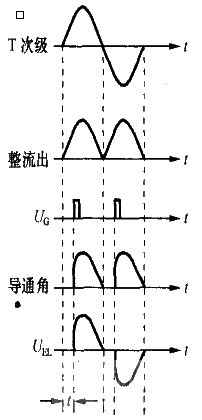
Transistors VT1 and VT2 form an equivalent unidirectional thyristor, VD5 is a trigger diode, EL is a 12V quartz bulb, and T is a power transformer. Resistor R1, potentiometer RP and capacitor C1 form a timing circuit, which generates a trigger voltage UG together with VD5. After the power is turned on, the 12V, 50Hz AC voltage on the secondary side of transformer T is rectified into a 100Hz pulsating current through diodes VD1~VD4. At the beginning of each half cycle, C1 is charged through R1 and RP. Since the charging current is very small, it is not enough to make the quartz bulb EL glow. As time goes by, when the charged voltage on C1 reaches the conduction voltage of VD5 (equal to the forward voltage drop of VD5 plus the eb junction voltage drop of VT2), VD5 turns on and outputs a trigger voltage UG, which turns on the equivalent thyristors VT1 and VT2, and EL glows. When the AC voltage passes through zero, the equivalent thyristor is turned off, and the above process is repeated at the beginning of the next half cycle. The figure is a schematic diagram of the working waveform, and "f" in the figure is the charging time. When the resistance value of R1+RP is small, the charging time f is short, the conduction angle of the equivalent thyristor is large, the voltage obtained on EL is large, and the light is brighter. When the resistance value of R1+RP is large, the charging time f is long, the conduction angle of the equivalent thyristor is small, the voltage obtained on EL is small, and the light is darker. The conduction angle of the equivalent thyristor can be changed by adjusting the potentiometer RP, thereby achieving the purpose of dimming.

Transistor VT1 uses PNP power amplifier tube 8550, and VT2 uses NPN power amplifier tube 8050. The parameters of both tubes are VCCO=40V, ICM=1.5A, PCM=1W, so this circuit is suitable for 12V, 10~15W quartz bulbs. If you want to control a quartz bulb with higher power, you should use a transistor with a larger ICM. If you want to control a 220V quartz bulb or other bulbs, you should use a transistor, diode and capacitor with sufficient withstand voltage (not less than 400V), and cancel the power transformer T. At the same time, special attention should be paid to personal safety during production.
- DIY a simple fire alarm
- How to Make a Simple 2-Step Arduino Programmable Timer Circuit
- Build a Smart Garage Door Opener Using a Raspberry Pi
- Build a glove-controlled robotic arm
- How to Build a Touch-Based Color-Changing Plant Using Arduino
- A small improvement on the ordinary refrigerator motor starting circuit
- Working principle of one Xipu STR soft starter controlling two motors
- IGBT modules block overcurrent by controlling the gate
- Audio interface protection circuit
- An experimental model of an infrared radio alarm
- Egg heating control circuit
- Pyroelectric automatic door control circuit
- fire smoke control circuit
- Photoelectric tracking control circuit
- Automatic tuning control circuit
- Timing and fire power control circuit
- Temperature detection control circuit of electric hot water bottle
- audio signal control circuit
- Inverter brightness control circuit
- Wide input range non-synchronous voltage mode control circuit


 京公网安备 11010802033920号