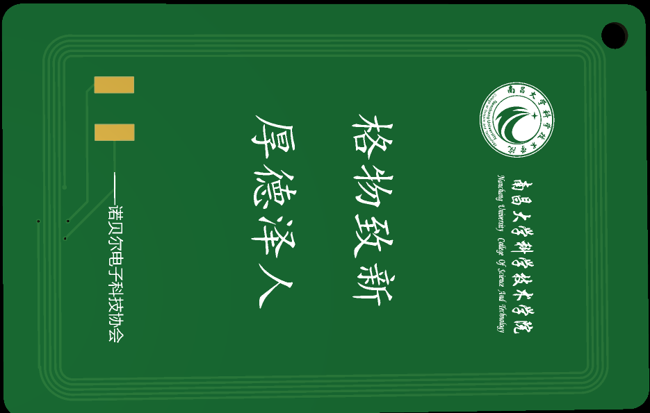
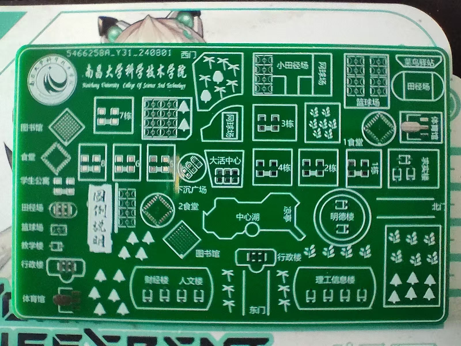
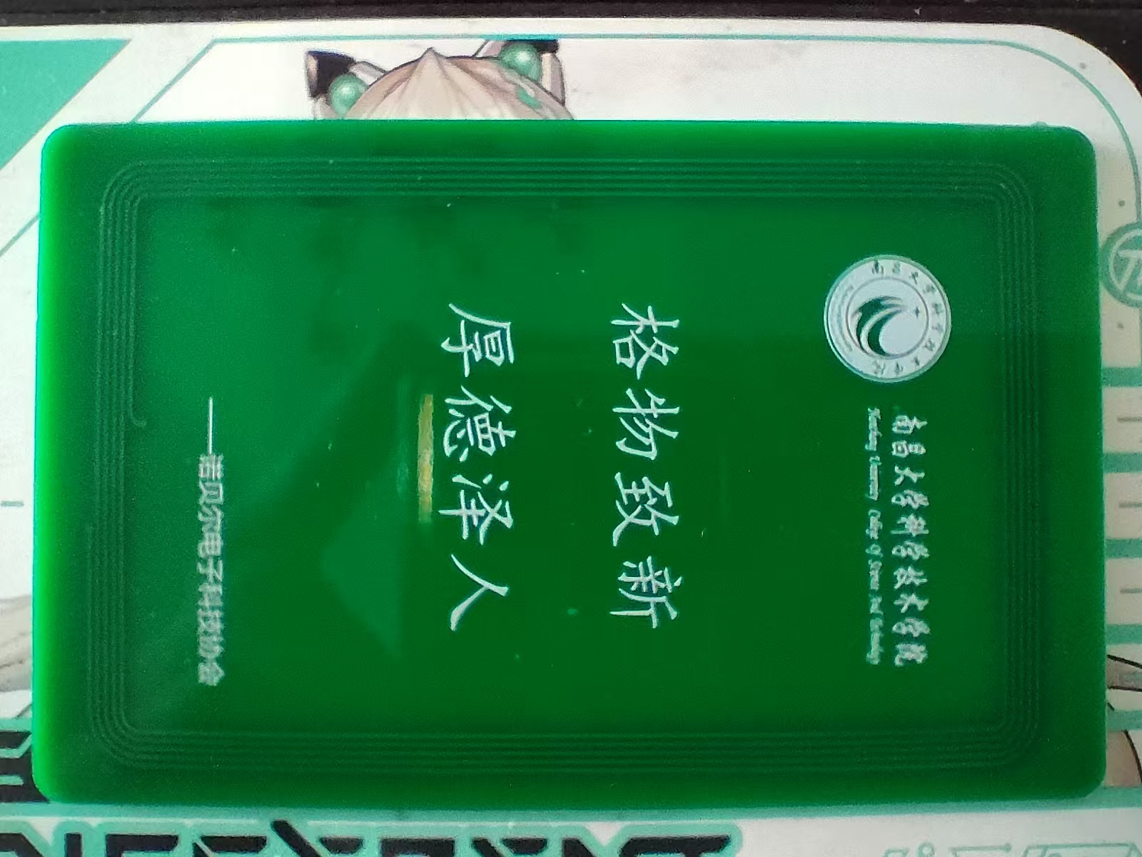
Campus map PCB card of Nanchang University School of Science and Technology;
suitable for self-installation of IC card chips;
details may vary during map production, for reference only;
this is a commemorative PCB card for club recruitment;
![QQ screenshot 20240820034136.png]

![QQ screenshot 20240820034348.png]
![abab69877c659d9ea5198eeae03a6d8.jpg]
![53e6f3a8f111f0c4381eab21de75474.jpg]
Nanjing University of Science and Technology PCB (image file)
Nanjing University of Science and Technology PCB reverse engineering.png
PDF_Nanchang University School of Science and Technology Campus Card PCB.zip
Altium_Nanchang University of Science and Technology Campus Card PCB.zip
PADS_Nanchang University of Science and Technology Campus Card PCB.zip
BOM_Nanchang University of Science and Technology Campus Card PCB.xlsx
93017
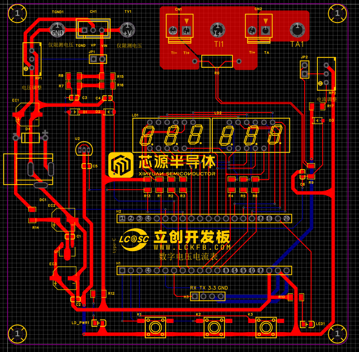
CW32 Voltage and Current Meter
The training camp program, a collaboration between LCSC Development Board and Wuhan Chipsource Semiconductor, primarily focused on learning the use of domestically produced MCUs and their ADC functions, as well as instrument calibration.
The training camp project, a collaboration between LCSC and Wuhan Xinyuan Semiconductor, utilizes the LCSC CW32F030C8Tx development board. This eliminates the need to design a minimum system, replaces the original DC interface with a Type-C interface, and omits the LDO chip, making it more convenient. The connectors have also been modified for greater robustness and reliability, and components have been replaced with surface-mount packages.
Voltage measurement is DC 0-30V, and current measurement is 0-3A.
The hardware section primarily focuses on voltage and current sampling circuits.
The software implementation includes a continuously flashing LED indicator and a digital tube display of current and voltage. A calibration function is also included: defining five operating modes. The K1 key switches between display modes. The K2 key sets the parameter values for the corresponding mode and saves them to FLASH. The K3 key returns to mode 0.
Mode 0: Displays normal voltage and current values (the upper row of the digital tube displays the voltage value *.V or .*V automatically switching, the lower row displays the current value _.**A).
Mode 1: Sets the 5V voltage calibration value. Mode 1: Voltage 15V Calibration Setting. The top row of the digital tube displays 5.05. The next row displays the current voltage value in _V or ._V. In this mode, the multimeter should be set to 5.00V when measuring the measured bit. After pressing the K2 key, the current value is
calibrated to 5V. Mode 2: Voltage 15V Calibration Setting. The top row of the digital tube displays 5.15. The next row displays the current voltage value in _V or ._V. In this mode, the multimeter should be set to 15.0V when measuring the measured bit. After pressing the K2 key, the current value is calibrated to 15V.
Mode 3: Current 0.5A Calibration Setting. The top row of the digital tube displays A.0.5. The next row displays the current current value in _.**A. After pressing the K2 key, the current value is calibrated to 0.5A.
Mode 4: Current 1.5A Calibration Setting. The top row of the digital tube displays A.1.5. The next row displays the current current value in *.**A. Pressing the K2 key will calibrate the current value to 1.5A.
This is the core part of this training camp: calibration to improve the accuracy and precision of instruments or systems.
PDF_CW32 Voltage and Current Meter.zip
Altium_CW32 voltage and current meter.zip
PADS_CW32 Voltage and Current Meter.zip
BOM_CW32 Voltage and Current Meter.xlsx
93018
Voltmeter and Ammeter
This project is a training camp project for the JLCPCB CW32 voltmeter and ammeter. It allows for manual calibration and adjustment of measured values. Training camp materials link: https://wiki.lckfb.com/zh-hans/dwx-cw32f030c8t6/
This design is based on the hardware circuit design
training camp curriculum. I also designed the 3D shell and panel myself; please refer to the editor for details.

Software design
and code are based on the training camp project materials: https://wiki.lckfb.com/zh-hans/dwx-cw32f030c8t6/, or the attached code.
Tutorial video: https://www.bilibili.com/video/BV1Fw4m1C7db/?vd_source=6c45053dd289c9fd041c3b9ef303819d.
Materials should be purchased
according to the project BOM.
Copper eyelets are required; they are not available on the LCSC website and are used to easily insert probes.
Assembly instructions:
Beginners are advised to use a heating table with solder paste for soldering; it's simple and easy to learn (I used a constant temperature 250°C heating table and medium-temperature solder paste). (Be careful with the heating table after use; it gets very hot!)
The 3D shell and panel
files can be found in the exported project file;
the physical verification video
is attached.
Project final code .7z
Measure voltage and current.mp4
Button demonstration.mp4
PDF_Voltage and Current Meters.zip
Altium_voltmeter_currentmeter.zip
PADS_Voltage and Current Meter.zip
BOM_Voltage and Current Meter.xlsx
93019
Hikvision PTZ camera module adapter board 2.1
Hikvision PTZ camera mechanism repair adapter board
Hikvision PTZ camera module repair adapter board. It's compatible with almost all Hikvision modules with a 36-pin interface. It provides a 485 interface, audio input/output interface, 232 interface, coaxial output interface, alarm input/output interface, and a reset button, provided the module supports these functions. Custom designs with additional interfaces are available upon request.
Demo video.mp4
PDF_Hikvision PTZ Camera Adapter Board 2.1.zip
Altium_Hikvision PTZ Camera Adapter Board 2.1.zip
PADS_Hikvision PTZ Camera Adapter Board 2.1.zip
93020
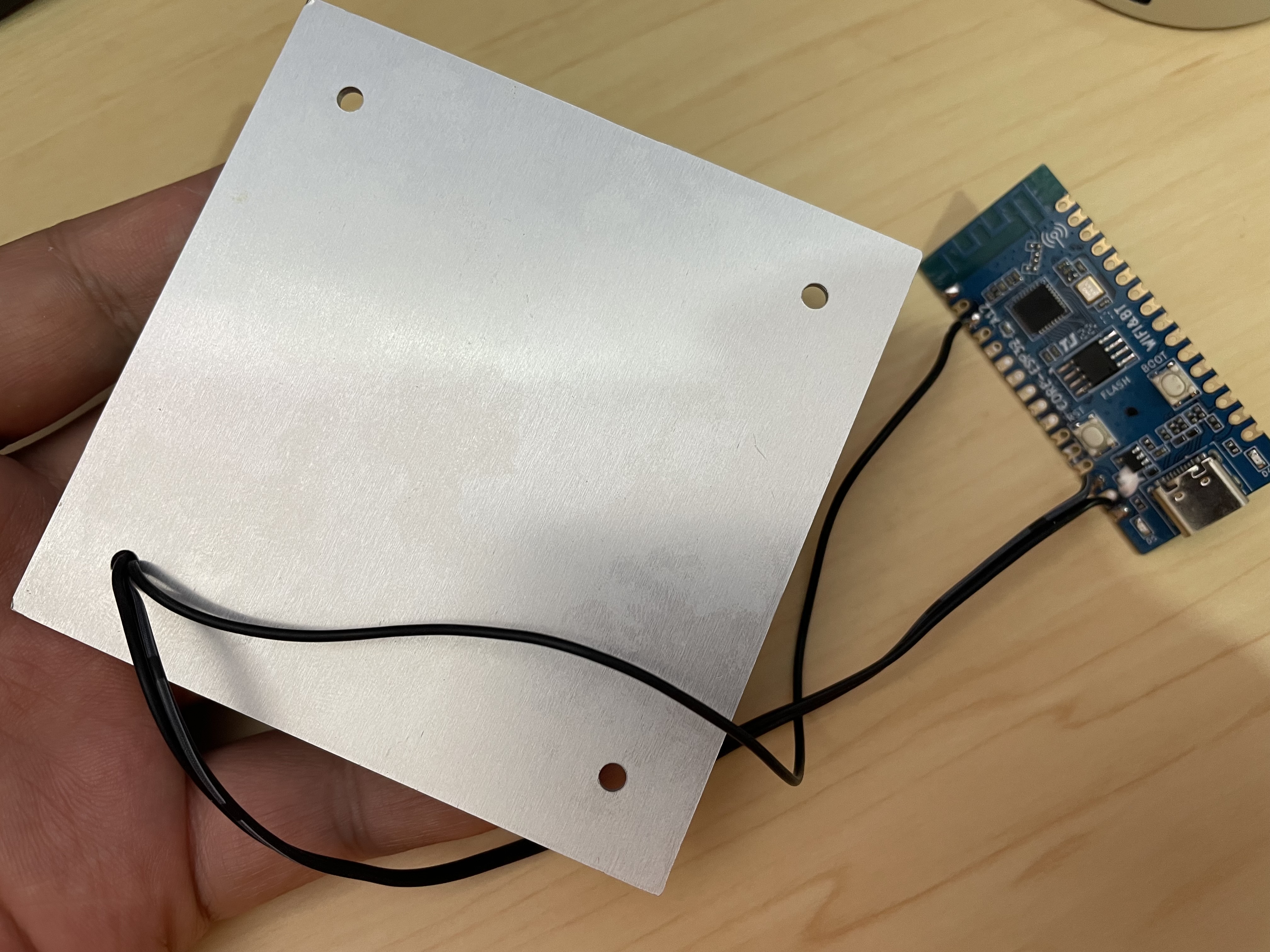
USB Wi-Fi control relay based on ESP33-WORK-32E
USB Wi-Fi switch
Original Requirements
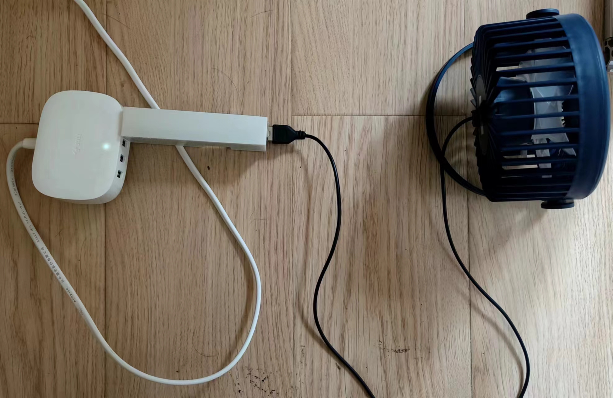
: 1. Initially, I used ordinary relays to control the fan and humidifier. However, ordinary relays have a problem: they make a "click-click-click" sound when engaging, which can easily cause insomnia when using a computer to automatically control temperature and humidity at night.
2. Using existing components also had issues. The 5V power lines for each circuit needed to be disconnected in the middle to connect to the relay, resulting in messy wiring and inconvenience. After testing
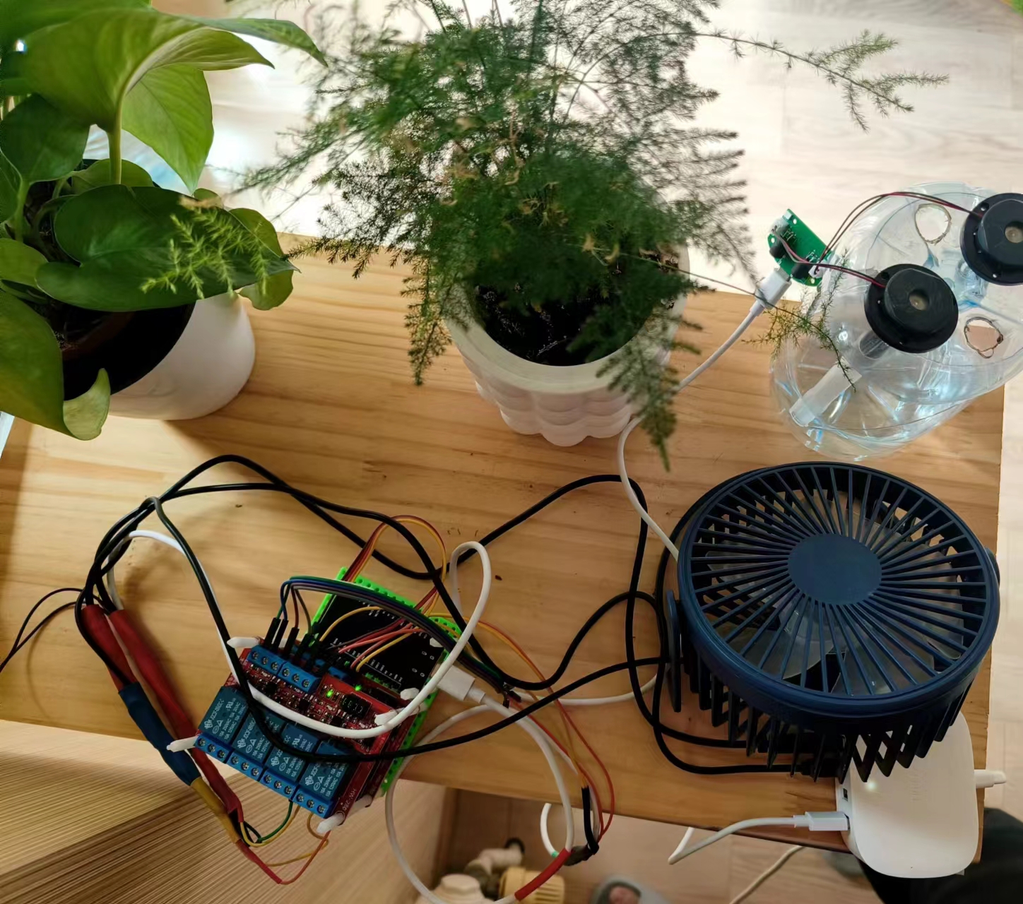
Wi-Fi control of the relays
, it felt wasteful, like using a sledgehammer to crack a nut.
First, there's no need for an ESP32; an ESP8266 is sufficient.
Second, there's no need for relays; two MOSFETs are enough.

Lessons Learned:
Try to be consistent between surface-mount and through-hole components. Use surface-mount components where necessary, and through-hole components where necessary. The lesson learned this time was that the inputs were all surface-mount, while the output relays and USB ports were through-hole. This made repairs more difficult if there were problems with the later circuitry, as through-hole components made soldering inconvenient. Therefore, consistency is crucial.
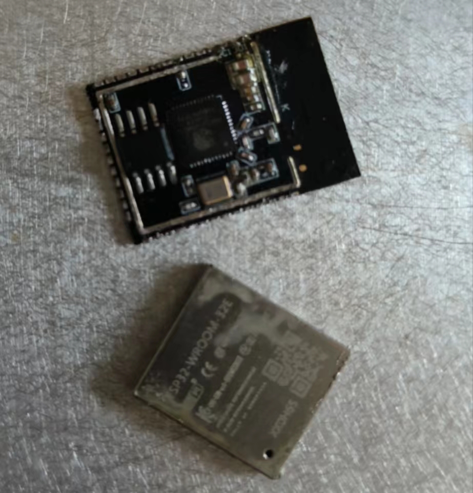
ESP32 soldering is problematic; beginners can easily ruin chips on their first attempt. If you have a heated soldering station, use one. Manual soldering is really prone to damaging chips (I ruined two myself). The first chip was damaged because I repeatedly soldered and disassembled it to familiarize myself with ESP32 soldering. As a result, I added too much rosin, and the ESP32 cover came off. The second chip was damaged because the two corner pins had solder bridging inside. When I tested it by applying a high level to the corresponding pins after powering it on, it burned out. (
Picture of the first damaged chip). So, if you have the means, use a JLCPCB SMT ESP32 . I've recently started practicing drawing traces, so I've encountered many problems. These are some issues I've encountered during the process; please try to avoid them. 1. The capacitors are not placed properly; the power lines should pass through the capacitors before reaching the components. 2. There should be clear space under the antenna, or it should extend beyond the edge of the board. 3. The 5V and 3.3V power lines are too close together. -8/13/Chen 1. There are many unnecessary bends in this power line; they could be straightened. 2. The signal lines don't need to be thickened; currently, thickening them makes them too close together. -8/14/Chen Summary: Although this project is usable and achieved its goals, it was a failure. Replicating it is not recommended; lessons should be learned.
PDF_USB port WiFi control relay based on ESP33-Wroom-32E.zip
Altium_USB port WiFi control relay based on ESP33-Wroom-32E.zip
PADS_USB port WiFi control relay based on ESP33-WORK-32E.zip
93022
Jiujiupai 2k0300 screen adapter board Loongson development board
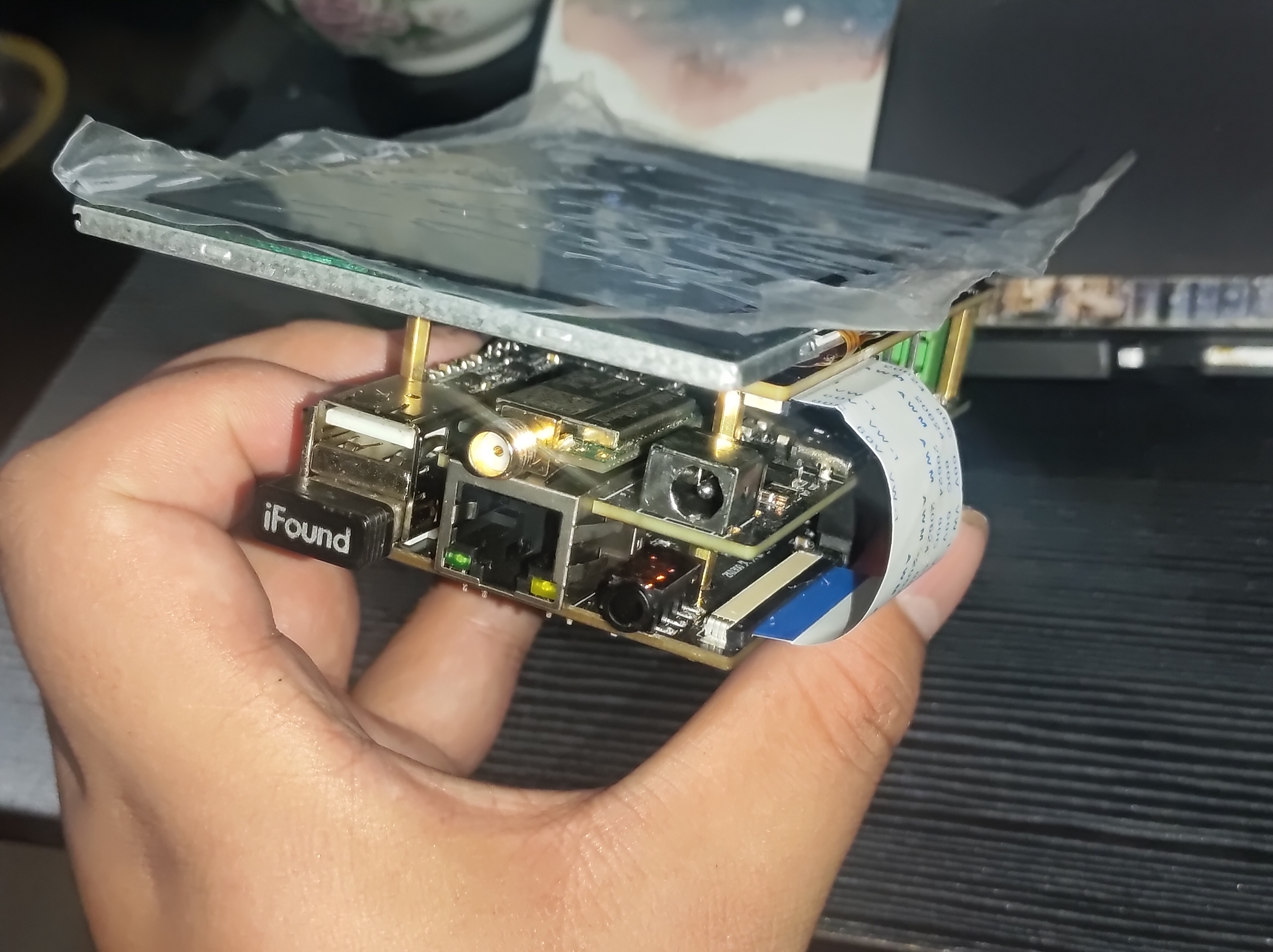
5-inch screen adapter board based on Zhongke Yunlongxin 2k0300 Jiujiupai development board
The screen used is a 5-inch RGB 800*480 capacitive touchscreen from Yaoyuanhong's Taobao store. (Link: Click to jump).
Before use, you need to modify the screen configuration and touchscreen configuration in the kernel file.
Zhongke Cloud Forum: https://bbs.ctcisz.com/
Note:
The 40P FPC connector is for connecting to
the 6P connector below; the FPC connector is for connecting to
the 54P connector above; the FPC connector is for connecting to the 54P connector below; the ribbon cable must be in the same direction.
PDF_Jiujiupai 2k0300 Screen Adapter Board Loongson Development Board.zip
Altium_久久派2k0300 screen adapter board Loongson development board.zip
PADS_久久派2k0300 screen adapter board Loongson development board.zip
BOM_久久派2k0300 screen adapter board Loongson development board.xlsx
93023
WS2812-5050 Aluminum Substrate 8x8 Lamp Board
WS2812-5050 Aluminum Substrate 8x8 Lamp Board
WS2812-5050 aluminum substrate 8x8 LED board. Aluminum substrates can also be custom-made for free. Give it a try! Better heat dissipation, suitable for LED boards, power supplies, and other

circuits with high heat generation. Video
introduction

:
https://www.bilibili.com/video/BV15iWAeJEc3
PDF_WS2812-5050 Aluminum Substrate 8x8 Lamp Board.zip
Altium_WS2812-5050 Aluminum Substrate 8x8 Lamp Board.zip
PADS_WS2812-5050 Aluminum Substrate 8x8 Lamp Board.zip
BOM_WS2812-5050 Aluminum Substrate 8X8 Lamp Board.xlsx
93024
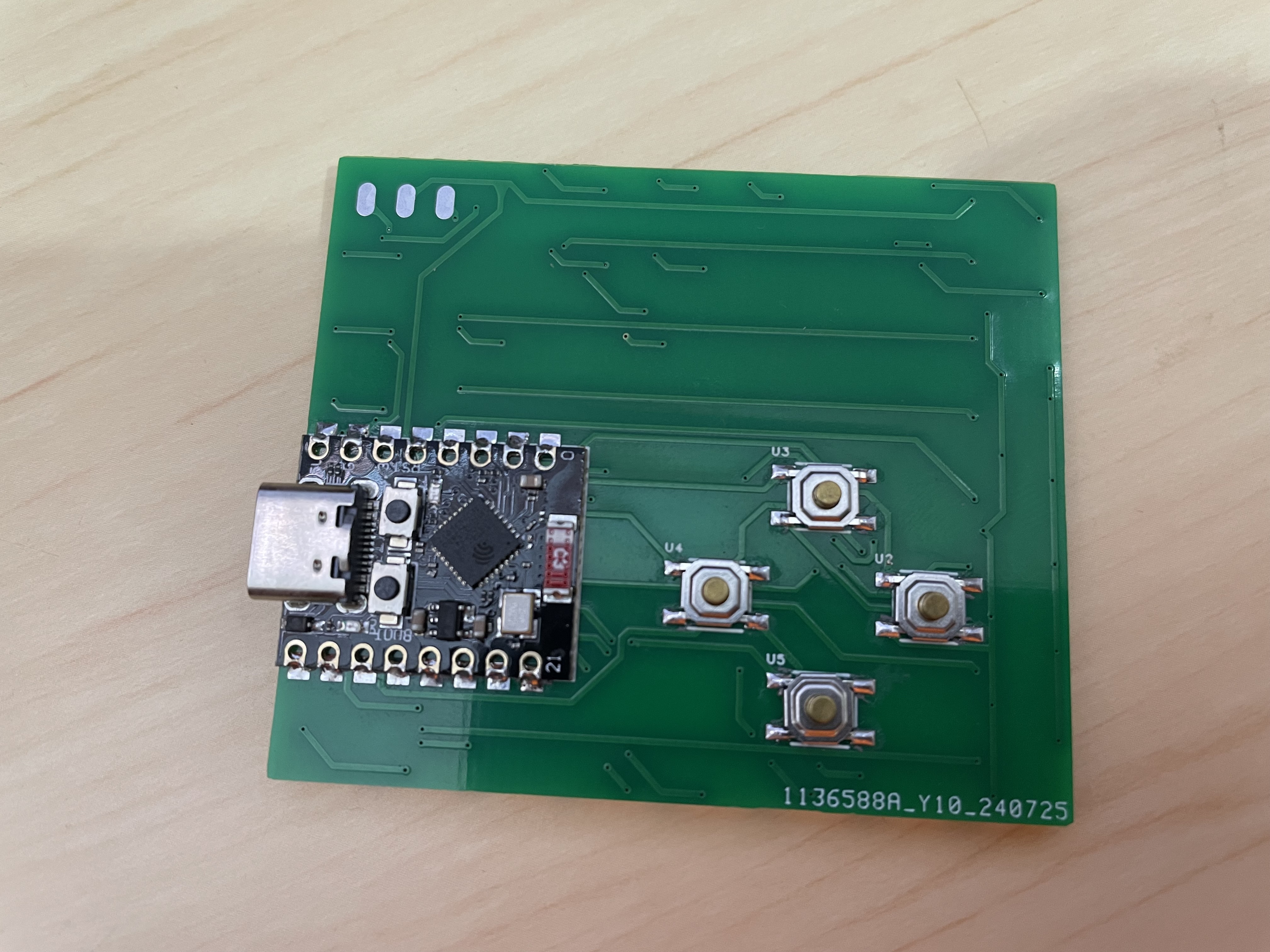
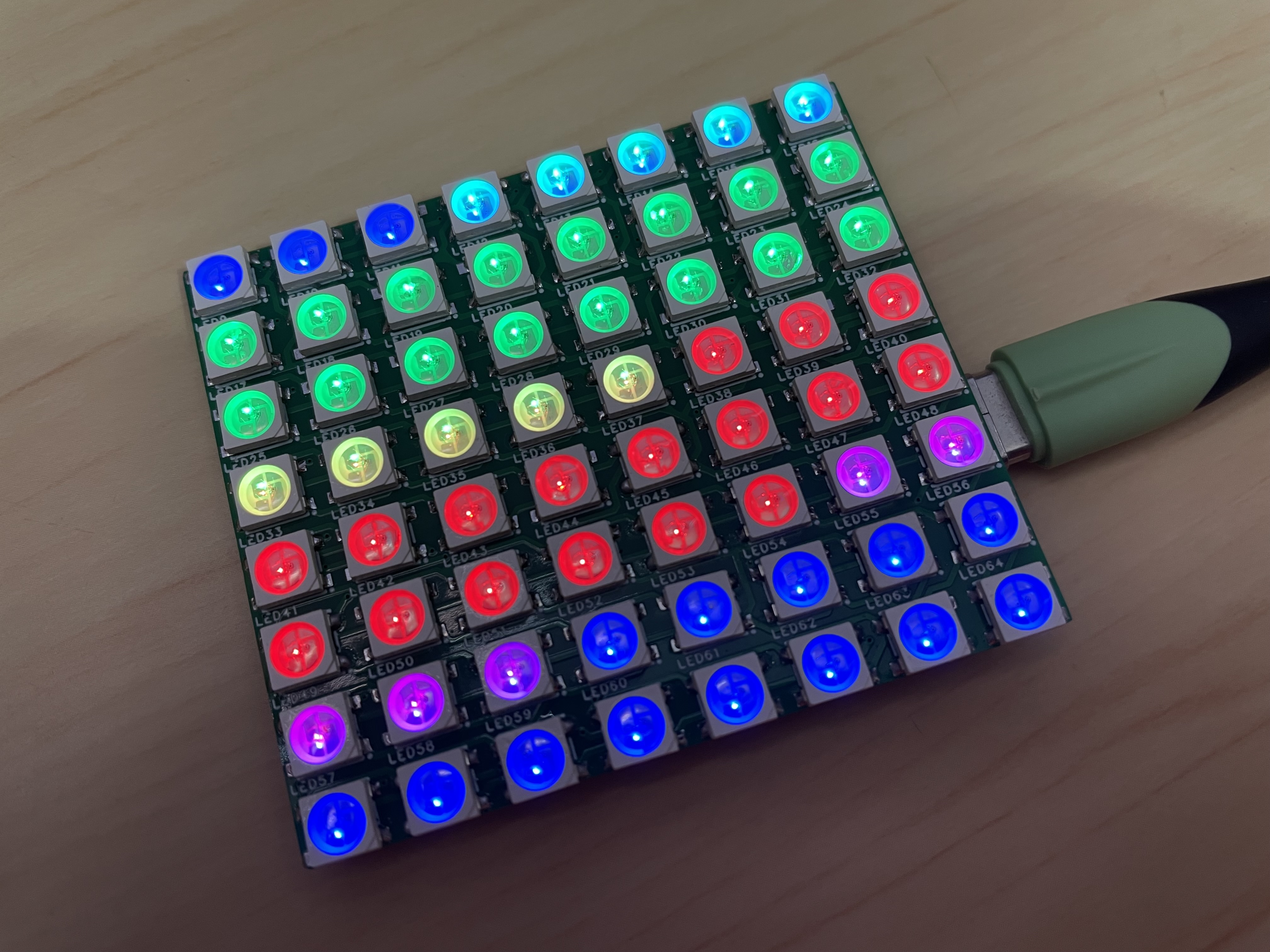
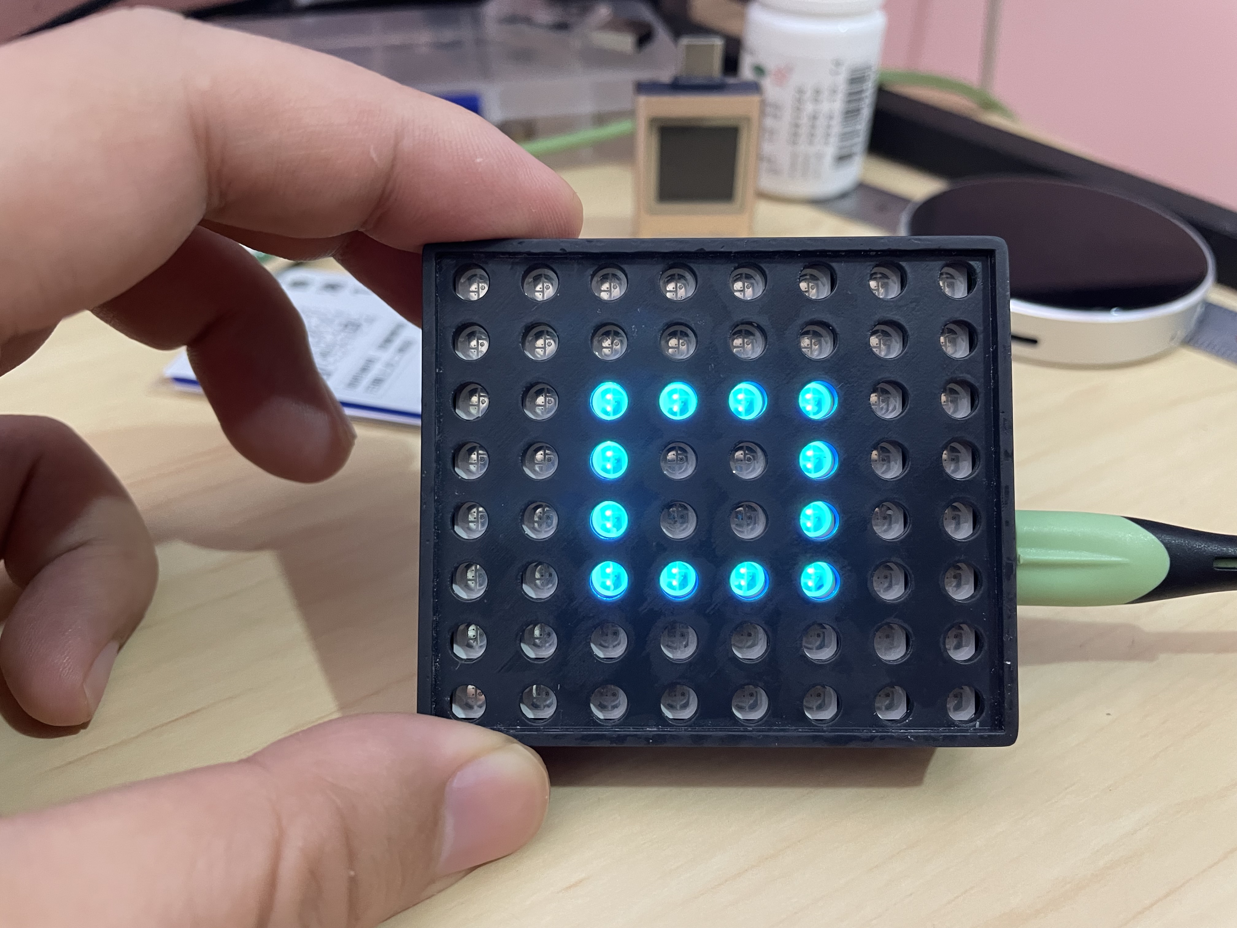
The WS2812-Matrix-8x8 uses the ESP32C3Mini driver.
Another 64-bit simple WS2812 full-color dot matrix ESP32C3 SuperMini JLCPCB prototype 3D printed shell Arduino+VSCode+PlatformIO
64-bit Simple WS2812 Full-Color Dot Matrix ESP32C3 SuperMini JLCPCB Prototyping 3D Printed Shell Arduino + VSCode + PlatformIO
Hardware: ESP32C3 SuperMini Development Board + WS2812
Software Platform: VSCode + PlatformIO + Arduino
Open Source Address: https://github.com/zhuhai-esp/ESP32-C3-WS2812-8X8-4Keys

Rear
Power-On Effect
3D Shell
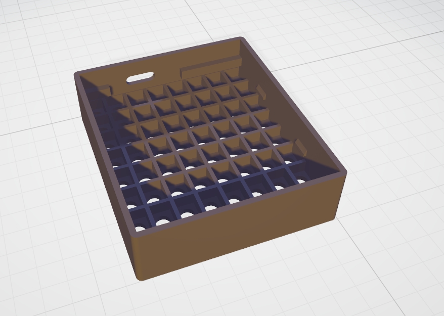
Shell Printed Object

Assembly Effect
Other: https://www.bilibili.com/video/BV1eeYKeSEiK
PDF_WS2812-Matrix-8x8 using ESP32C3Mini driver.zip
Altium_WS2812-Matrix-8x8 uses ESP32C3Mini driver.zip
PADS_WS2812-Matrix-8x8 uses ESP32C3Mini driver.zip
BOM_WS2812-Matrix-8x8 uses ESP32C3Mini driver.xlsx
93025
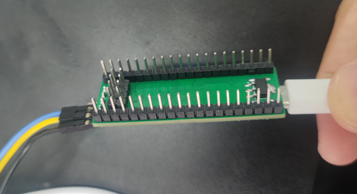
MSPM0G3507 core board
The MSPM0G3507 core board is pin-compatible with LCSC's Dimensity Components, has a smaller size, and also features an SPI interface for connecting to an LCD screen. This core board was created for the 2024 National Electronic Design Contest; after the contest, we open-sourced this core board and its baseboard.
The schematic and PCB design describe
the use of a CH340 for the serial port. The serial port pins are not exposed; connection is only possible via USB.
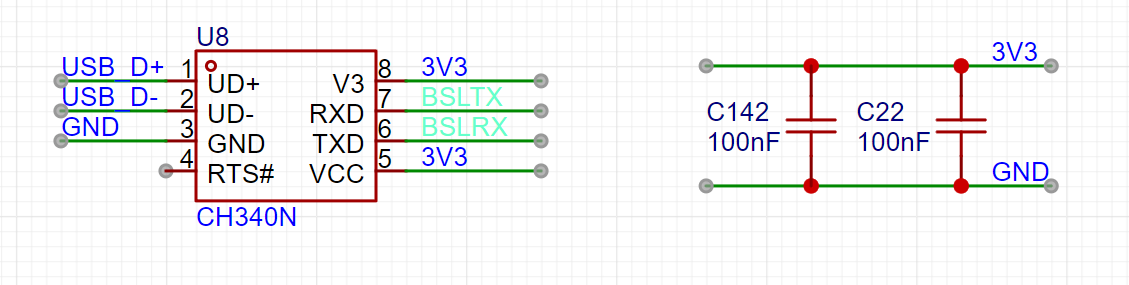
An 1117 power supply is used primarily for its affordability and ease of soldering.

The SPI interface is brought out for connecting to the LCD screen. Two attached images are

shown. A quick note: during the competition, one of the judges immediately asked me if it made sense for us to buy a ready-made board, and whether I thought this was a good practice for our competition. I almost died laughing. I explained that this was our lab's board, with my LCSC logo on it; it was a question-and-answer format. He asked me about the crystal oscillator frequency, and after I answered, he said to the person next to him, "This is the baseboard you designed yourself." I asked him if he had anything else to say, and he replied, "Don't say anything, I already know." I almost died laughing.


PDF_MSPM0G3507 core board.zip
Altium_MSPM0G3507 core board.zip
PADS_MSPM0G3507 core board.zip
BOM_MSPM0G3507 core board.xlsx
93026
electronic


 京公网安备 11010802033920号

 D114I
D114I


