0. Introduction:
The initial design purpose was to facilitate continuous current and voltage testing and output recording to a computer. The main goal was to facilitate development and testing.
Regarding accuracy, the system consists of two parts: a sampling front-end and a back-end processing unit
. The sampling front-end is extremely rudimentary, mainly for functional verification, and there is still considerable room for optimization (when floating, the current range has a baseline but fluctuates; the voltage range has a baseline and is relatively stable; the zero-value can be set separately via the Modbus interface).
The back-end uses the BH45B1225, mainly because it is easy to purchase, reasonably priced, and has a continuously adjustable PGA (1~128).
1. Measurement Parameters
: Measurable DC voltage ≤24V, DC current ≤1A (resistance voltage divider 1:101, current sampling resistor is 10mR).
In the code, the voltage range using 8 times the PGA can measure 2500/8 = 312.5mV, and the current range using 128 times the PGA can measure 2500/128 = 19.53125mV.
Combining the above measurement ranges with the voltage divider or sampling resistor, the actual voltage input range is ≤31V, and the current input range is ≤1.9A.
The voltage resolution is approximately 0.12mV (currently there is no range division mechanism, calibration is troublesome), and the current resolution has not yet been tested with instruments.
2. Function Introduction: 1.
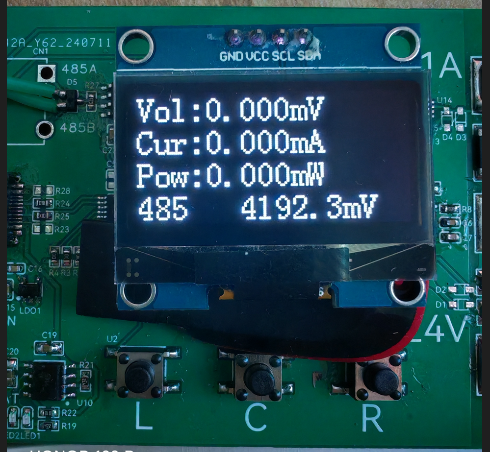
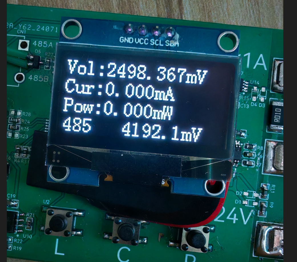
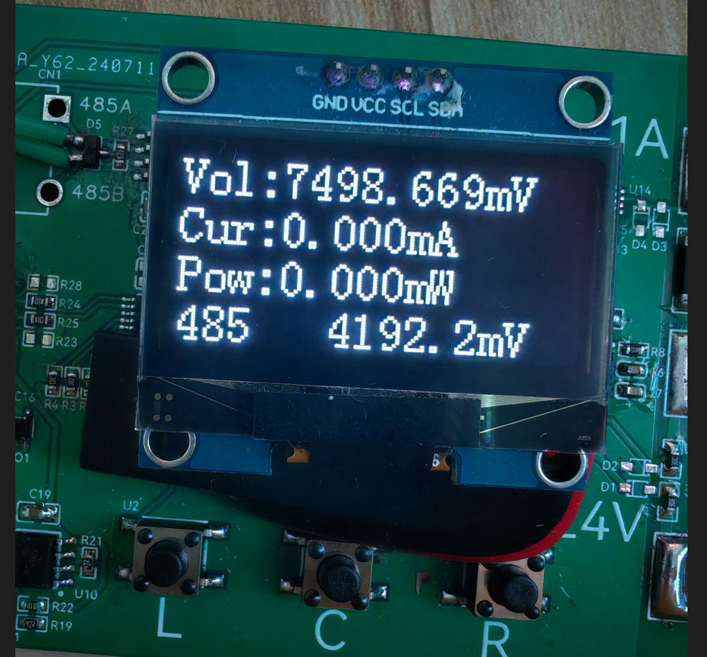
485 Mode ("485" is displayed in the lower left corner of the screen; long press "L" to switch to this interface; this is the default interface after power-on).
In this mode, the screen displays... The first mode displays voltage, current, "instantaneous" power, and battery voltage, with an approximate update frequency of 3Hz.
External devices can access the device's time, measured values, calibration parameters, etc., via a 485 interface based on the Modbus protocol.
This mode is suitable for simple voltage and current testing or for use in embedded user devices.
2. Log Mode (displayed in the lower left corner of the screen; long press "C" to switch to this interface).
In this mode, the screen sequentially displays voltage, current, "instantaneous" power, and battery voltage, with an approximate update frequency of 3Hz.
External devices actively report time and measured values to the 485 port, with an approximate update frequency of 1Hz (reporting format is CSV, convenient for serial port to receive files and form tables).

This mode is suitable for simple voltage and current testing, or for recording voltage and current values to a computer.
3. Settings Mode (displayed at the bottom of the screen) (Press and hold "R" to switch to this interface)
In this mode, the screen displays the voltage calibration value (default 101.000), current calibration value (default 100.000), and battery voltage calibration value (default 5.700)
in sequence. External devices can access the device time, measured values, calibration parameters, etc., via the 485 interface based on the Modbus protocol.

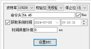
In this interface, you can also use the "RTC Time Synchronization" function in the STC programming software to calibrate the time (tested successfully using stcai-isp-v6.94H).
Let me briefly explain the calibration values. The voltage and battery voltage calibration values are easy to understand. Regarding the current, I'll briefly explain that
the default 100.000 is derived when the sampling resistor is 10mR, but for some reason, when I actually tested the resistor, it only carried 1A of current. The voltage drop across the resistor was measured to be over 12mV,
so I simply reduced the calibration value by about 1.2 times and then fine-tuned it. The final value of 80.989 was found to be acceptable.
Therefore, the calibration value should be adjusted according to the actual resistor size during fabrication.
3.
The Modbus register table is attached, along with a simple user guide.
In Log reporting mode, Modbus commands are not responded to. It is recommended to open the serial port software first, check "Save to file," and then switch to Log mode to avoid losing the CSV header.
When programming, press the "L" button before powering on the chip. The device to be programmed will then appear in the programming software. Programming parameters are in the attached file. (The attached
file contains "ReceivedTofile-COM24-2024_7_21_17-56-47") - "copy.CSV" contains the device's serial port output to the file in Log mode. The measurement object is a lithium battery (not the lithium battery that powers the device; please pay special attention here).
During testing, please note that the 485 pin is not isolated, and the device's power supply should not be introduced into the measurement circuit. When measuring above 24V, pay special attention to electrical sparks; safety first.
4. Simple test

(Bilibili link: Power Measurement Mode).
5. Protocol Description:
Communication Parameters 115200 8N1 only responds to Modbus commands in non-Log mode.
Register Address Table: typedef enum{ AppPort_ModbusReg_Addr = 0, AppPort_ModbusReg_Time_H, AppPort_ModbusReg_Time_L, AppPort_ModbusReg_Voltage_H, AppPort_ModbusReg_Voltage_L, AppPort_ModbusReg_Current_H, AppPort_ModbusReg_Current_L, AppPort_ModbusReg_Power_H, AppPort_ModbusReg_Power_L, AppPort_ModbusReg_Vin_H, AppPort_ModbusReg_Vin_L,
AppPort_ModbusReg_Voltage_ADC_H,//11 AppPort_ModbusReg_Voltage_ADC_L, AppPort_ModbusReg_Current_ADC_H, AppPort_ModbusReg_Current_ADC_L, AppPort_ModbusReg_Vin_ADC,
AppPort_ModbusReg_VoltageGain_H,//16 AppPort_ModbusReg_VoltageGain_L, AppPort_ModbusReg_CurrentGain_H, AppPort_ModbusReg_CurrentGain_L, AppPort_ModbusReg_VinGain_H, AppPort_ModbusReg_VinGain_L,
AppPort_ModbusReg_VoltageDrop_H,//22 AppPort_ModbusReg_VoltageDrop_L, AppPort_ModbusReg_CurrentDrop_H, AppPort_ModbusReg_CurrentDrop_L,
AppPort_ModbusReg_CustomArea_S,//26 AppPort_ModbusReg_CustomArea_E = (AppPort_ModbusReg_CustomArea_S+12),}AppPort_ModbusReg_E;
Address 0: Modbus address, modifiable range 1~247, please do not change to 0, default address is 1 (if the exact address is unknown, send 255, the device will respond accordingly) Addresses 1~2: Current device time, UTC format Addresses 3~4: Voltage measurement value, 1000 times the actual value Addresses 5~6: Current measurement value, 1000 times the actual value Addresses 7~8: "Instantaneous" power estimation value, 1000 times the actual value Addresses 9~10: Battery voltage measurement value, 10 times the actual value Addresses
11~12: Voltage ADC, 18-bit Addresses 13~14: Current ADC, 18-bit Addresses 15: Battery voltage ADC, 12-bit
Addresses 16-17: Voltage calibration value, 1000 times the true value, default 101.000 Addresses 18-19: Current calibration value, 1000 times the true value, default 100.000 Addresses 20-21: Battery voltage calibration value, 1000 times the true value, default 5.700
Addresses 22-23: Voltage zeroing value, 1000 times the true value; measurements less than this value will be zeroed, default 0.5mV Addresses 24-25: Current zeroing value, 1000 times the true value; measurements less than this value will be zeroed, default 1.0mA
Addresses 26-38: Custom boot string, supports '
'Newline, please write a string of no more than three lines, otherwise it will block the boot progress bar
6.
The OLED refresh part uses analog IIC, and for convenience, it uses full-screen refresh, so the above frequencies all use the modifier "approximately".
Regarding the accuracy part, I used 1% conventional resistors in my tests. I feel that the voltage range is okay
, but the current range is not suitable. Regarding the code part, this is my first time using an STC microcontroller, and the code I wrote is really, well, hard to describe. I won't open source it to embarrass myself. If you encounter any problems during the replication, please feel free to give me feedback. In terms of
hardware, I am only a novice and know that there is still a lot of room for improvement. Please give me more guidance.
The measurement reference in the picture is when the air conditioner is on, and the measurement reference in the video is when the air conditioner is off. The temperature drift is quite obvious.
Later, temperature compensation and low temperature drift resistors need to be added. The voltage also needs to be measured in different ranges. The current detection part probably needs to be redesigned, otherwise there is not much meaning to the replication.' After using the STC8H
microcontroller, I feel it's quite good, especially the STC-compatible ISP host computer, which really considers the needs of developers and even the production process.
Of course, there are a few issues. When using STC's single-chip emulation in USB mode at full speed, the computer fan spins wildly, almost like it's about to take off! (Driver version V1.19)
It would be even better if the breakpoints could be switched on and off at full speed and the variable periodic updates could be improved. I look forward to Mr. Yao's update. Even so, I still want to give Mr. Yao a huge shout-out for bringing us so many high-quality and affordable products. To be fair
, LCSC EDA has become increasingly mature over the years, and some features have indeed improved work efficiency. Moreover, they offer two free shipping opportunities every month without any barriers, which is simply a blessing.
I thank STC & LCSC EDA for organizing this event, which allowed me to verify my design ideas. Thank you all for your support.


 京公网安备 11010802033920号

 SI6435DQ


