Outdoor lighting is usually switched on or off manually with a mechanical switch. Suppose, however, that you do not want to illuminate an area for the whole night. In that case, it would be advantageous to control the illumination more precisely so you can automatically switch the lighting off/on at a prescribed time.
A controller can sense ambient light, turn lights on when it gets dark, track a time interval, and automatically turn the lights off at a specified time. In the morning, the process can be reversed. If the ambient light level is under a preset lux threshold at a predetermined time, the system will turn on the light. It will turn the light off when the ambient gets bright enough to surpass the same lux threshold.
It is not difficult to design an intelligent lighting controller that senses and measures the ambient light level with an ambient light sensor (ALS). Equipped with a real-time clock (RTC), the controller also knows when to turn lighting on or off at specified times. The system presented here can be used to control all luminaires that are mains supply operated. The controller's lux-level threshold is fully programmable in single-lux steps. Controller software is provided in hex format.
The lighting controller in this design needs to measure the ambient light level, which is done with an ALS. There are two different kinds of ALS products in the market today: one outputs the analog voltage proportional to the ambient light level, and the other gives the output in digital format. This system uses the ALS with the digital output.
The controller needs to know the exact time, so a real-time clock (RTC) is used. To anticipate possible power loss, the time information needs battery backup.
A user interface is needed for setting time and other parameters. The user interface here consists of two 7-segment LED displays and one pushbutton. With a short button press, the system displays time and other parameters. With a long button press, the time and parameters can be adjusted.
The system has an auto/manual switch to enable switching the light on or off manually.
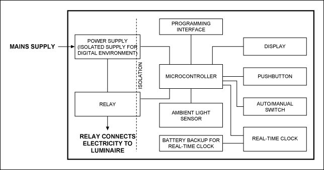
System power comes from the mains supply. Electricity to the luminaire is switched on/off through a relay. The digital portion of the system is isolated from mains supply.
The system block diagram is shown in Figure 1.

Figure 1. Lighting controller system.
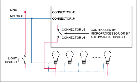
Figure 2 further illustrates the system wiring to the mains supply voltage and to luminaire(s).

Figure 2. System wiring to the mains supply voltage and to luminaire(s).
When the system is used in manual mode, the auto/manual switch must be switched to manual. In manual mode, the relay is continuously on and the luminaires are switched on/off using a standard wall light switch.
When the auto/manual switch is in auto mode, the standard wall light switch must be switched on so the controller can function. If that wall switch is not on, the controller cannot switch the luminaires on.
One system can contain multiple luminaires.
All reference designs on this site are sourced from major semiconductor manufacturers or collected online for learning and research. The copyright belongs to the semiconductor manufacturer or the original author. If you believe that the reference design of this site infringes upon your relevant rights and interests, please send us a rights notice. As a neutral platform service provider, we will take measures to delete the relevant content in accordance with relevant laws after receiving the relevant notice from the rights holder. Please send relevant notifications to email: bbs_service@eeworld.com.cn.
It is your responsibility to test the circuit yourself and determine its suitability for you. EEWorld will not be liable for direct, indirect, special, incidental, consequential or punitive damages arising from any cause or anything connected to any reference design used.
Supported by EEWorld Datasheet