Gitee repository address: https://gitee.com/zzwzt/oscilloscope_STM32F407
1. Project Background
By chance, I came across a video on Bilibili by Teacher Tang explaining the principles of the STC open-source oscilloscope. I wanted to make my own handheld oscilloscope to improve my skills, so I created my first open-source project—a handheld oscilloscope based on the Air32. However, this project still had many imperfections and some functional deficiencies, hence this project, which can be considered an upgrade of the previous one.
2. Functions and Features
* Simultaneously functions as an oscilloscope and signal generator (can simultaneously measure and output two signals); * Oscilloscope maximum sampling rate 2MHz, bandwidth 50KHz, input voltage range -50~+50 * Signal generator can generate sine waves, square waves, and triangle waves, with an output voltage range of 0~3.3V and a maximum output frequency of 10KHz. * Operates using two three-way switches.
December 8, 2023
* Optimized operation smoothness
* Implemented pre-trigger function, displaying waveforms before and after triggering * Added trigger condition selection, temporarily supporting both rising and falling edge modes * Added trigger mode selection, supporting automatic triggering and single triggering; single triggering can acquire a momentary waveform
3. Hardware Design
This project uses the STM32F407VET6 as the main control chip, with a main frequency of up to 168MHz; the oscilloscope preamplifier circuit references the STC oscilloscope preamplifier circuit; for display, a 3.5-inch TFT high-definition color screen (resolution 480*320) is used, with 16-bit parallel port communication. The operation method uses two three-way switches. A touch method was tried, but it was inconvenient to operate and too expensive, so it was not adopted. The charging chip uses the TP4056 linear charging chip, with a charging current of 0.9A. Although it generates significant heat, it is inexpensive, and given the small battery capacity used, this was chosen for the time being.
Screen Recommendation Link: https://item.taobao.com/item.htm?spm=a1z09.2.0.0.23b52e8dAoyY3G&id=636897428918&_u=f2iletacd766
Battery Recommendation Link (1800mAh, 3.7V/XH2.54 reverse plug): https://item.taobao.com/item.htm?spm=a1z09.2.0.0.23b52e8dAoyY3G&id=539644377788&_u=f2iletacd726
Screws: Use M3*12 self-tapping screws.
4. Software Design:
The software uses CubeMX to configure the underlying driver, and I ported the LVGL open-source graphics library myself.
5. User Manual

Figure 5.1 Main Interface
As shown in Figure 5.1 above, this is the first interface after powering on. The interface is relatively simple, with one button on each side. No icons are used to avoid copyright infringement. The left button enters the oscilloscope interface, and the right button is the signal generator interface. Control is achieved by toggling the three-way switch in the upper left corner.
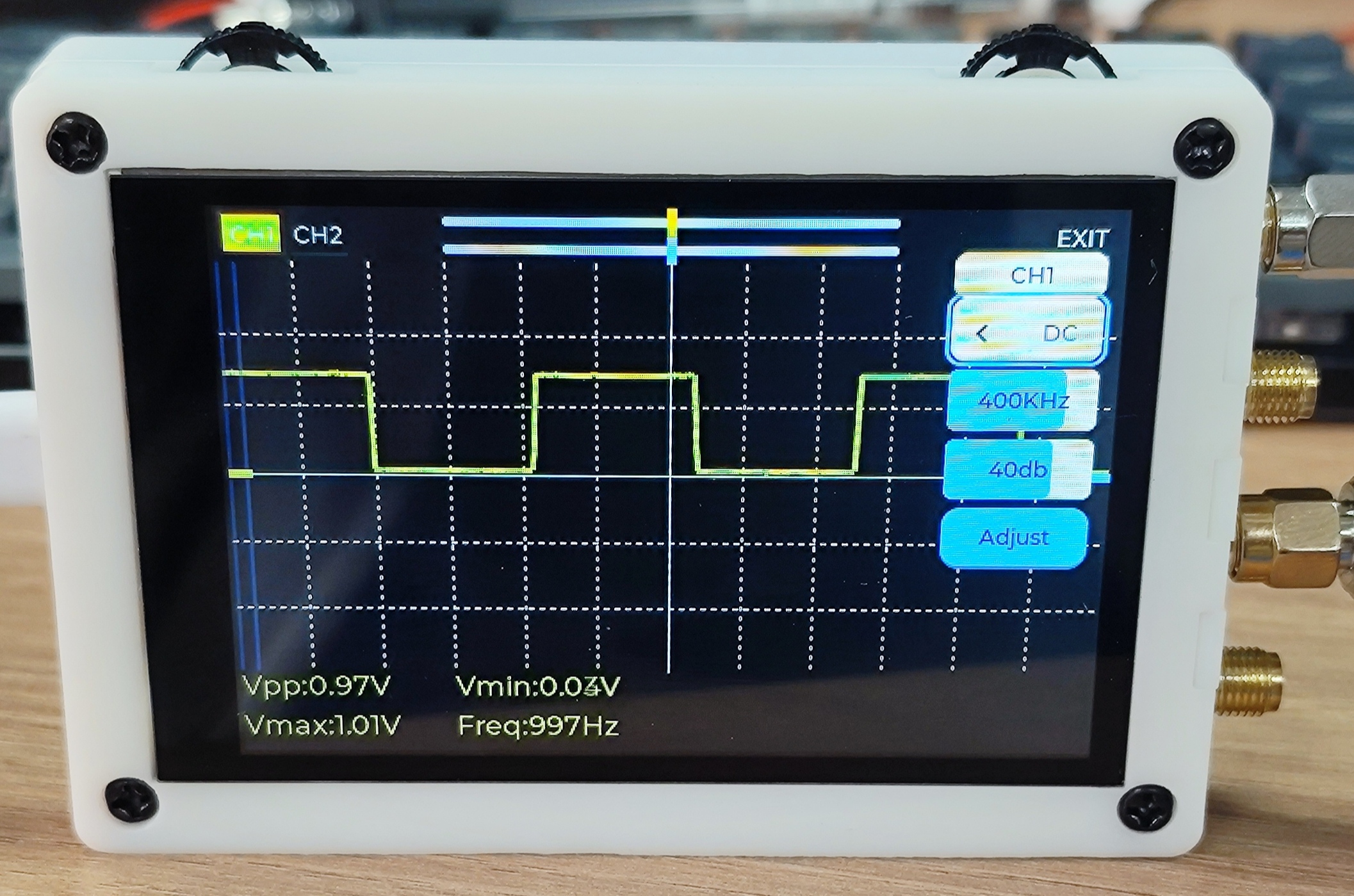
Figure 5.2 Oscilloscope Interface
Press the left button in Figure 5.1 to enter the oscilloscope function. As shown in Figure 5.2, the oscilloscope interface is displayed. Toggling the three-way switch in the upper left corner allows you to focus on the CH1 button, CH2 button, yellow slider, blue slider, and EXTI button in sequence. A short press of the CH1 button turns channel 1 on or off, and the same applies to CH2. When focused on the slider, a short press enters edit mode. Toggling the three-way switch in the upper left corner controls the left and right offset of the waveform. A short press of EXTI exits the oscilloscope interface and returns to the main interface. Press and hold the CH1 button. A settings interface will pop up from the left. The top shows which channel the current setting corresponds to. Flip the three-way switch in the upper right corner to focus on the coupling method, sampling rate, preamplifier gain, and calibration. When the settings interface is not displayed, flipping the three-way switch in the upper right corner allows you to select the vertical offset of two channel waveforms. The bottom displays the peak-to-peak value, maximum value, minimum value, and frequency parameters of the waveform. Here, we'll focus on why calibration is necessary. The circuit will boost the acquired waveform by 1.65V. Due to resistor errors, this will cause some offset, so calibration is required. When the oscilloscope probe is shorted, if the line displayed on the screen is not centered (provided the vertical offset is adjusted to the center), focus on the Adjust button and then press and hold to start calibration. After calibration, the parameters will be saved to the AT24C02 and will be automatically read and applied upon the next power-on.
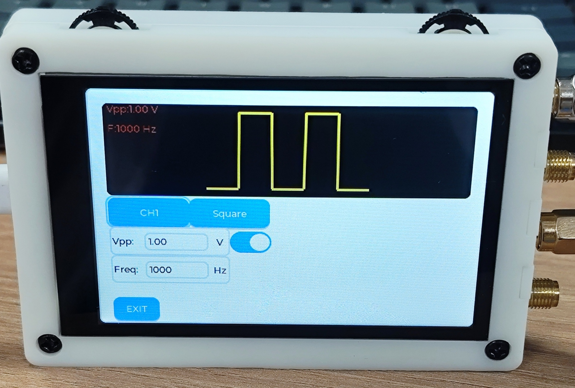
Figure 5.3 Signal Generator Interface.
Press the button on the right of Figure 5.1 to enter the signal generator function. Flip the three-way switch in the upper left corner to sequentially focus on the channel switching button, waveform switching button, maximum value setting button (currently the minimum value is fixed at 0V), frequency setting button, output switch, and exit button. See the video for detailed operation instructions.
6. Examples and Demonstrations
: https://www.bilibili.com/video/BV1ue411Z7hE/
https://www.bilibili.com/video/BV1KC4y1w7kL/
7. Expansion and Improvements
: * There will definitely be some bugs and shortcomings in the program. If you find any bugs, please send me a private message, and I will resolve them promptly.
* The higher the measured frequency, the greater the error; further improvement is needed.
* This is more expensive than the previous one. The cost of components, plus the 3D printing cost of the casing, brings the DIY cost to around 170 RMB. Shipping costs may be even higher.
* Currently, only bin and hex files are provided for the software; schematics, PCB files, and 3D casing files are provided for the hardware.
8. Other
* If you want to understand the principles, you can watch Teacher Tang's videos on Bilibili about oscilloscopes in the electronics design competition; he explains it very clearly.
* I graduated this year and currently have a full-time job. These open-source projects were all done in my spare time because of my passion for them.
* Why doesn't the software provide source code? It will provide bin and hex files, so you can replicate it even without the source code. As mentioned earlier, these open-source projects were completed in my spare time. The initial PCB fabrication, 3D printing, and component consumption were considerable expenses for me. Plus, I just graduated and my wallet isn't very wealthy. To support my continued open-source work, I chose this method. For those who want the source code, you can add me on WeChat (17674119712) for a flat price of 9.9 RMB (technical support included), with free updates.
* If you're too lazy to do it yourself, you can also add me on WeChat to purchase. I'll also list it on Taobao later, charging only a labor fee. The current price is 199 RMB (source code included; price may vary depending on component costs, including shipping up to 9 RMB). Open-source projects do not currently support returns or refunds.


 京公网安备 11010802033920号

 2SD2553


