EEI TECHNOLOGY 01P-HexaGon Series Project EPA-INBN33B3092IA
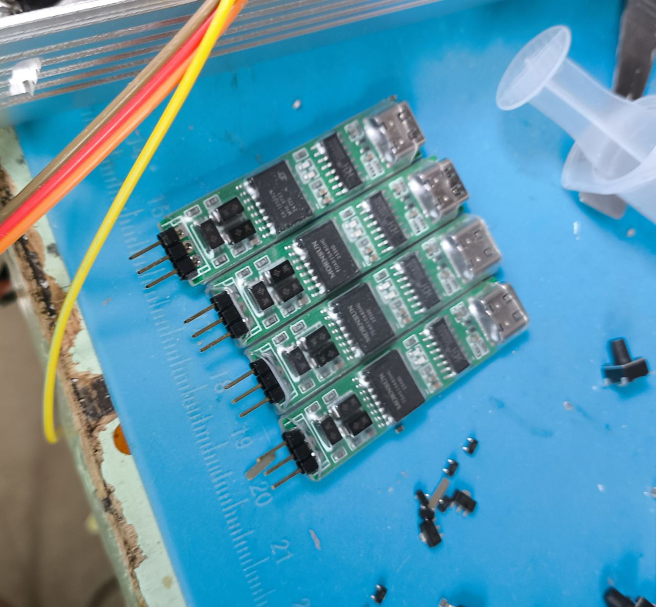
is an electrically isolated RS-485 converter based on CA-IS3092W.
It features hardware-based automatic transmit/receive logic,
a maximum baud rate of 500Kbps,
integrated isolated power supply with short-circuit and overcurrent protection,
idle bus failure protection,
1/8 unit load (96KΩ input impedance),
a driver with a maximum short-circuit output current of 150mA,
ESD protection for RS-485 terminals,
and electrical isolation strength up to 5000V (RMS). It
supports USB-CDC and is driverless for Win10 and Win11. Note: The
RS
-485 terminals can be soldered with 2.54mm screws for
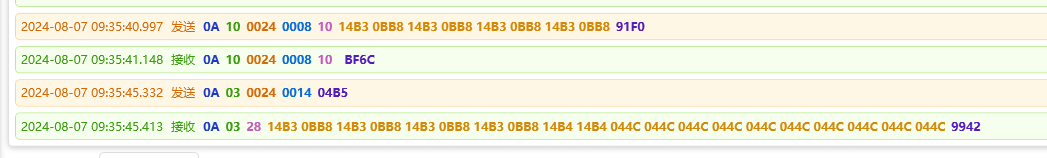
connection to devices for debugging,
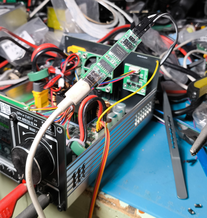
normal write and read operations .
(Board front view)
PDF_Industrial Field Debugging Tool [Electrically Isolated USB to RS485].zip
Altium - A Powerful Tool for Industrial Field Testing [Electrically Isolated USB to RS485].zip
PADS - A Powerful Tool for Industrial Field Testing [Electrically Isolated USB to RS485].zip
BOM_Industrial Field Debugging Tool【Electrically Isolated USB to RS485】.xlsx
93260
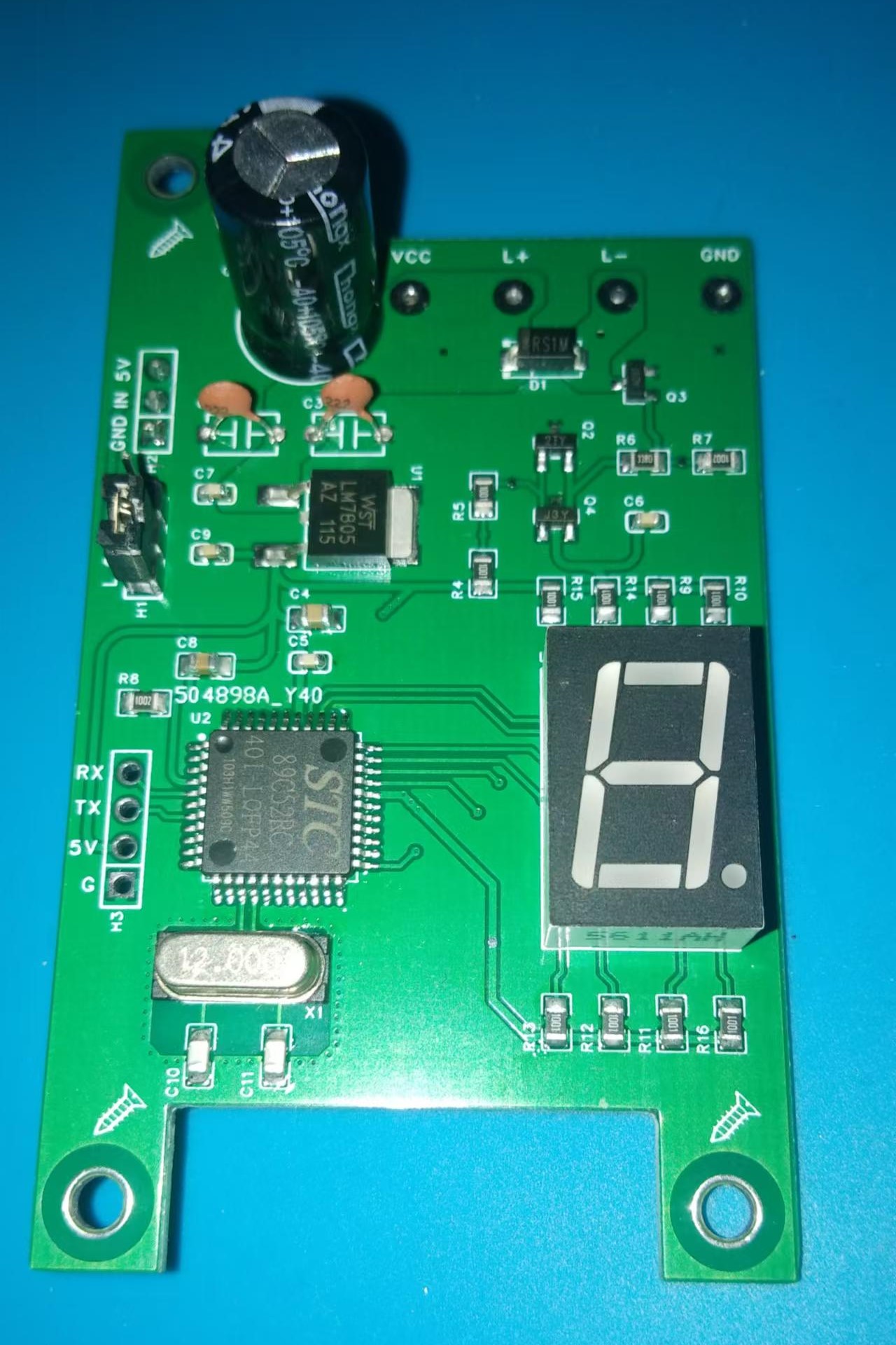
Water tank level controller
This project is a water tank level controller based on the 51 microcontroller. Using this design, the water level of any water tank can be effectively limited. With the right sensor and actuator, it can also be used for the level control of other liquids.
1. Design Purpose:
To control the water tank level in a relatively simple way.
2. Electrical Characteristics
: Input Voltage: 8~35V DC (limited by 7805)
3. Workflow:
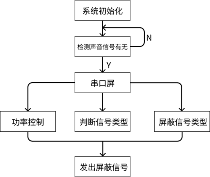
After the system is powered on, it immediately initializes all I/O ports and waits for a period of time until the system stabilizes. Then, it immediately executes the digital tube test function to facilitate visual inspection of the digital tube for damage.
After the check program completes, the system enters the normal working process. In the timer interrupt function, the microcontroller reads the float switch once every certain period of time (based on timers TL and TH) to determine whether the water level has dropped.
If no water level drop is detected, the digital display shows a standby animation. If a water level drop is detected, the digital display will show a countdown of approximately 6 seconds (actually starting from the 5th second) before rechecking the water level to prevent malfunctions caused by water surface fluctuations or external interference. During this time, the float switch will continue to be read. If no water level drop is detected, the system returns to the standby screen and starts a new round of checks. If a water level drop is still detected after 6 seconds, the system is considered to be in a valid state, and the microcontroller executes the water filling action. Current can flow between L+ and L- under the control of the MOSFET, energizing the normally closed solenoid valve (or other actuator) connected to it, and water begins to be filled into the tank. The digital display shows a water filling animation.
After the water filling action is executed, the system records the water filling time. Before the water filling time reaches the upper limit (approximately 330 seconds), the float switch detects that the tank is full, performs approximately 1 second of de-shaking, and then checks again. If the tank is found to be full, water filling stops immediately, the digital display returns to the standby screen, and the system enters a new cycle. If the float switch does not detect a full water level before the water filling time reaches its maximum (approximately 330 seconds), the float switch is considered faulty, the system immediately stops water filling, and an "Err" error message is displayed on the digital tube. To prevent a complete water overflow, once the system enters the error state, it will only resume normal operation after the microcontroller is reset.
4. Precautions:
1. Please refer to the schematic diagram for component identification; do not use the system-generated BOM
. 2. When soldering power supplies, pay close attention to polarity.
3. Take precautions against water damage in actual applications
. 4. I am not a professional programmer; feedback on any bugs encountered during use is welcome.
shuxiangkongzhi.hex
PDF_Water Tank Level Controller.zip
Altium_water tank level controller.zip
PADS_Water Tank Level Controller.zip
BOM_Water Tank Level Controller.xlsx
93261
2024 National Electronic Design Contest, Problem G: Simple Recording Shielding System
This design utilizes the nonlinear characteristics of a microphone to create a blocking recording shielding system. It interferes with the sound signal by using beat frequency signals generated by ultrasonic noise signals, making the recording device unable to record.
I. Team Introduction
Our team is from Guangdong Transportation Vocational College, and we won the provincial first prize in the 2024 Electronic Design Contest. This open-source project only releases the hardware design scheme; the software source code is not yet open-source.
II. Project Requirements
Design and build a simple blocking recording jamming system (hereinafter referred to as the "jamming system"), including: a recording jamming signal generator (hereinafter referred to as the "signal generator") and an audio signal monitoring/identification module. It should be able to block (selectively block) recording/playback devices and ordinary recording equipment without affecting normal audio communication. The sound generator is responsible for emitting an audio signal with an intensity of normal human conversation sound pressure level (≈50dB/1m), a duration of not less than 10 seconds, and the ability to repeat playback. The recording/playback device can receive, record, and play back audio signals in the frequency range of 100Hz~20kHz, containing storage space sufficient for recording audio signals of ≥10 seconds in length. The sound generator and recording/playback device can be powered by a mobile phone. The working principle block diagram of the shielding system is shown in Figure 1.

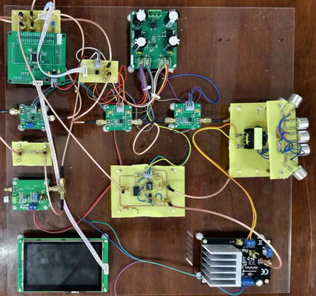
III. Design Summary
This design utilizes the nonlinear characteristics of a microphone to create a blocking recording shielding system. It interferes with the sound signal by using a beat frequency signal generated by ultrasonic noise, preventing the recording device from recording. The system first generates a white noise signal using an STM32F405 microcontroller. Then, it filters the white noise using a high-pass filter with a fixed cutoff frequency (25kHz) and a programmable low-pass filter with a settable cutoff frequency, generating a noise signal within a specific frequency range. The amplitude of this noise is then controlled and its power amplified. Finally, it is emitted into the air by an ultrasonic transducer matrix. When the microphone receives this ultrasonic signal, its nonlinear characteristics generate a signal with a large amplitude and a wide sound frequency range, causing the microphone to "block" due to voltage saturation, thus interfering with the normal operation of the recording system.
IV. Problem Analysis
This problem uses ultrasonic transducers. Many ultrasonic transducers are available on the market, including common ultrasonic probes and ultrasonic vibrators. However, how to drive them to operate is crucial. Common solutions using a matrix of ultrasonic probes don't effectively address distance and angle issues, although they can achieve shielding. The shielding effect depends on the number of probes, but this approach is wasteful and generally ineffective. (During a review, I saw a team create a circle filled with ultrasonic probes, but the evaluation results were mediocre). Therefore, this project uses a dedicated 25kHz ultrasonic shield. Below is a more detailed analysis of this task.
Requirement 1: Meeting the shielding distance and angle requirements is sufficient. The distance depends on the distance from which the ultrasonic waves originate, and the angle depends on the placement.
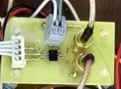
Requirement 2: The simplest approach is to use a microphone, amplify the signal, perform envelope detection, and then use a voltage comparator. Use I/O ports to control LEDs. It's particularly important to use the MAX9814 AGC (Automatic Gauge Control), as audio AGCs offer significant advantages and facilitate later requirements.
Requirement 3: The main issue is programmable power control. For convenient adjustment, a touchscreen is recommended for better visualization.
Requirement 4: Identify and automatically shield different audio segments. Using an audio AGC is one of the best methods here. After collecting and analyzing the FFT data, the frequency of human voices is lower, while the frequency of singing is higher.
V. Overall Design Block Diagram:
The MAX9148 amplifies the signal acquired by the microphone, indicating the presence or absence of sound. The STM32F405 microprocessor is the core of the entire system, primarily digitizing and analyzing the ambient sound signal. It uses its built-in DAC to generate the white noise needed for interference. Users interact with the system via a touchscreen LCD to control the interference system's operation. The MCP41010 digital potentiometer adjusts the amplitude of the interference white noise, thereby adjusting the input power of the interference system. The MAX297, with a fixed cutoff frequency of 20kHz and a programmable cutoff frequency of 20kHz, processes the full-spectrum white noise into narrowband white noise, thus interfering with specific frequency sound signals.

VI. Hardware Circuit Composition
: Power Supply: To provide better stability for the entire solution, a transformer power supply is used. Except for the power amplifier, which has a separate ±15V power supply, all other components use ±5V power.

Sound Acquisition Module: The AGC of the MAX9814 is a purchased integrated module. The MAX9814 features automatic gain control, and the 40dB amplification used in this design is sufficient to meet the design requirements.

The main controller is a self-designed F405. Due to the need for stable wiring throughout the system, all terminals use KF250 terminals.

The digital potentiometer module MCP41010 allows for programmable resistance adjustment, facilitating control of the white noise output and power control requirements. This module only requires the suggested adapter interface.
Initially, a 20kHz high-pass filter was used, but testing revealed that 25kHz was more suitable, so a fourth-order Butterworth high-pass filter was adopted. This is a voltage-controlled high-pass filter, which better meets the stopband and passband requirements. The
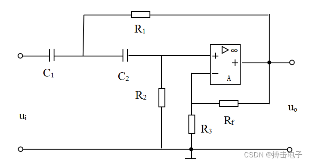
low-pass filter is a MAX297 programmable low-pass filter, an eighth-order low-pass, elliptic function, switched-capacitor filter. Its cutoff frequency can be controlled by a clock. The cutoff frequency is: clock/50. For example, to output a 100kHz square wave signal (the signal needs to be 5V high level and 0V low level), the cutoff frequency is 2kHz. This means that signals with frequencies below 2kHz can pass through our IN port, but frequencies above 2kHz will not pass. The low-pass filter range is between 25-40kHz.

After high-pass and low-pass filtering, the signal is within the desired white noise range (25-40kHz).
Our white noise is then directly amplified by the power amplifier. We are using the LM1875 (actually, Class D amplifiers are more efficient, but we didn't have time to purchase one). This module is readily available; our signal doesn't need excessive amplification, so the power amplifier only needs 11x amplification.

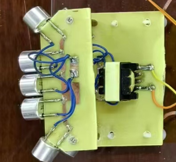
Transducers: We are using 25kHz shielded ultrasonic probes, with 10 probes used, sufficient for the two layers. After amplification, we added a step-up transformer to the board, allowing VPP to reach over 60V, meeting our requirements.
The program flowchart is as follows:
VIII. Physical display
: Acrylic boards and isolation columns are used for secure fixing. SMA connecting cables and KF250 are used extensively. A large number of filter capacitors are added to each board to prevent power supply noise from interfering with the signal. SMA connecting cables are used to make the signal transmission more stable. KF250 terminals can better connect the power lines and will not cause problems such as unreliable power supply.
IX. Actual test results
(1) Measurement results when the output power is 1W
No.
Distance (meters)
Angle (degrees)
Interference result
1
1
60
Success
2
1
90
Success
3
1
120
Success
4
1
180
Unsuccessful
(2) Measurement results when the output power is 2W
No.
Distance (meters)
Angle (degrees)
Interference Result
1
1
60
Success
2
1
90
Success
3
1
120
Success
4
1
180
Unsuccessful
(3) Measurement Result when Output Power is 3W No.
Distance
(meters)
Angle (degrees)
Interference Result
1
1
60
Success
2
1
90
Success
3
1
120
Success
4
1
180
Unsuccessful
(4) Measurement Result when Output Power is 4W
No.
Distance (meters)
Angle (degrees)
Interference Result
1
1.2
60
Success
2
1.2
90
Success
3
1.2
120
Success
4
1.2
180
Unsuccessful
After testing, the maximum interference distance of this design is 2 meters, and the maximum interference angle is 120 degrees.
X. Precautions
Pay attention to the wiring and soldering. Be sure to use SMA connection cable. Traditional DuPont cable is very easy to be loosely connected, causing unstable signal transmission and interference.
XI. Demonstration Video
The video will be uploaded later, as the overall design scheme still needs to be improved.
12.
Currently, only the hardware schematic (PCB) is uploaded as an attachment; the rest is not yet open source.
PDF_2024 Electronic Design Contest Problem G_Simple Recording Shielding System.zip
Altium_2024 Electronic Engineering Contest Problem G_Simple Recording Shielding System.zip
PADS_2024 Electronic Design Contest Problem G_Simple Recording Shielding System.zip
BOM_2024 Electronic Engineering Contest Problem G_Simple Recording Shielding System.xlsx
93262
[Open Source] STM8S003F3 Ultra-Mini System
The STM8S003F3 minimum system uses a Type-C power supply, with all GPIOs brought out, and has an area the size of a fingernail.
It can be used as a motherboard for small-scale STM8S003F3 microcontroller projects.
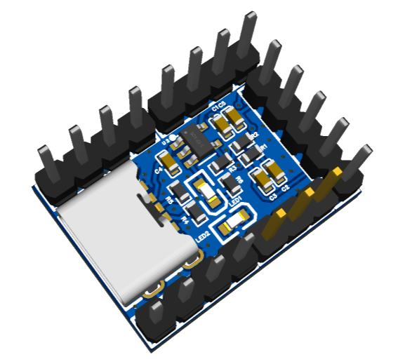

The actual product

includes a power indicator light and another indicator light connected to the PD4 pin for debugging the firmware.
BOM_STM8S003F3_STM8S003F3_2023-04-20.xlsx
Gerber_STM8S003F3_2023-04-20.zip
PickAndPlace_STM8S003F3_2023-04-20.xlsx
Test routines.docx
Physical demonstration.mp4
PDF_【Open Source】STM8S003F3 Ultra-Mini System.zip
Altium_【Open Source】STM8S003F3 Ultra-Mini System.zip
PADS_【Open Source】STM8S003F3 Ultra-Mini System.zip
BOM_【Open Source】STM8S003F3 Ultra-Mini System.xlsx
93263
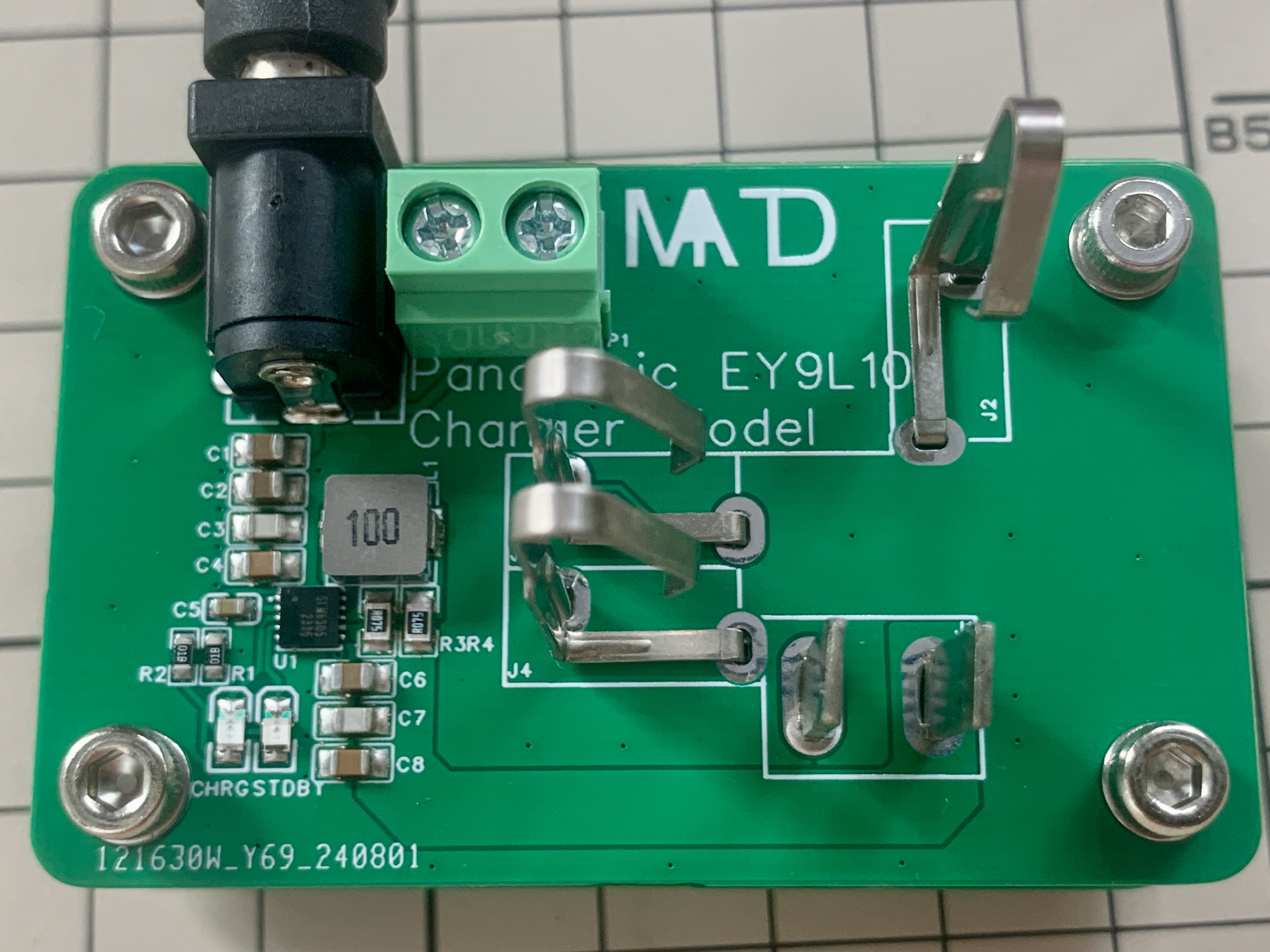
SLM6305 4.2V2A Wide Input Charger
For chargers based on the SLM6305 chip, LCSC can surface mount all components.
Advantages of the SLM6305 solution:
1. Wide input
voltage range: 5-26V, can be powered by USB, a standard 12V adapter, and 24V.
2. High charging current:
Maximum charging current can be set to 2.5A.
3. Compact size:
With optimized layout, it is comparable to or even smaller than the TP4506 solution.
Item Parameters:
Input Voltage: 12V;
Charging Cut-off Voltage: 4.2V;
Charging Current: 2A;
Supports NTC.
Main Component Parameters:
C1-C4: Input filter, total capacity recommended to be 30UF or higher, 310UF or 222UF can be used, 25V capacitor can be used if the input voltage is less than 15V.
C5: Internal driver capacitor, 0.1UF 50V X7R or higher, 25V capacitor can be used if the input voltage is less than 15V.
R1 & R2: Chip charging indicator current limiting resistor, official recommendation 1K, LED too bright under high voltage input conditions, 2K or 4.7K recommended.
For L1, an inductor of 6.8-10uH is selected. The charging circuit does not require excessively high dynamic response; commercially available circuits typically use 4.7uH inductors, which can lead to significant chip heat generation. This project uses an inductor to meet the 2A and 2.5A charging current requirements
. For R3 and R4, based on charging currents of 1A = 67mΩ, 1.5A = 44mΩ, 2A = 33mΩ, and 2.5A = 27mΩ, considering PCB layout requirements and resistor power, two 0805 package resistors are used in parallel to distribute the power and meet the project requirements. For a charging current of 2.5A, three 0805 package resistors need to be used in parallel to ensure that the rated power of the resistors is not exceeded
. The overall resistance value of the resistors cannot be less than 26.7mΩ; otherwise, the nominal 2.5A current will be exceeded.
R5 and R6 are NTC resistors. If the NTC function is not used, R5 or R6 should be a 1MΩ resistor; leaving them floating is not recommended. Using the NTC function, select 10K B3950K resistors
C6-C8. The total output capacitor capacitance should be less than 30uF.
For more design requirements, please refer to the datasheet.
During charging, there is no heat generation
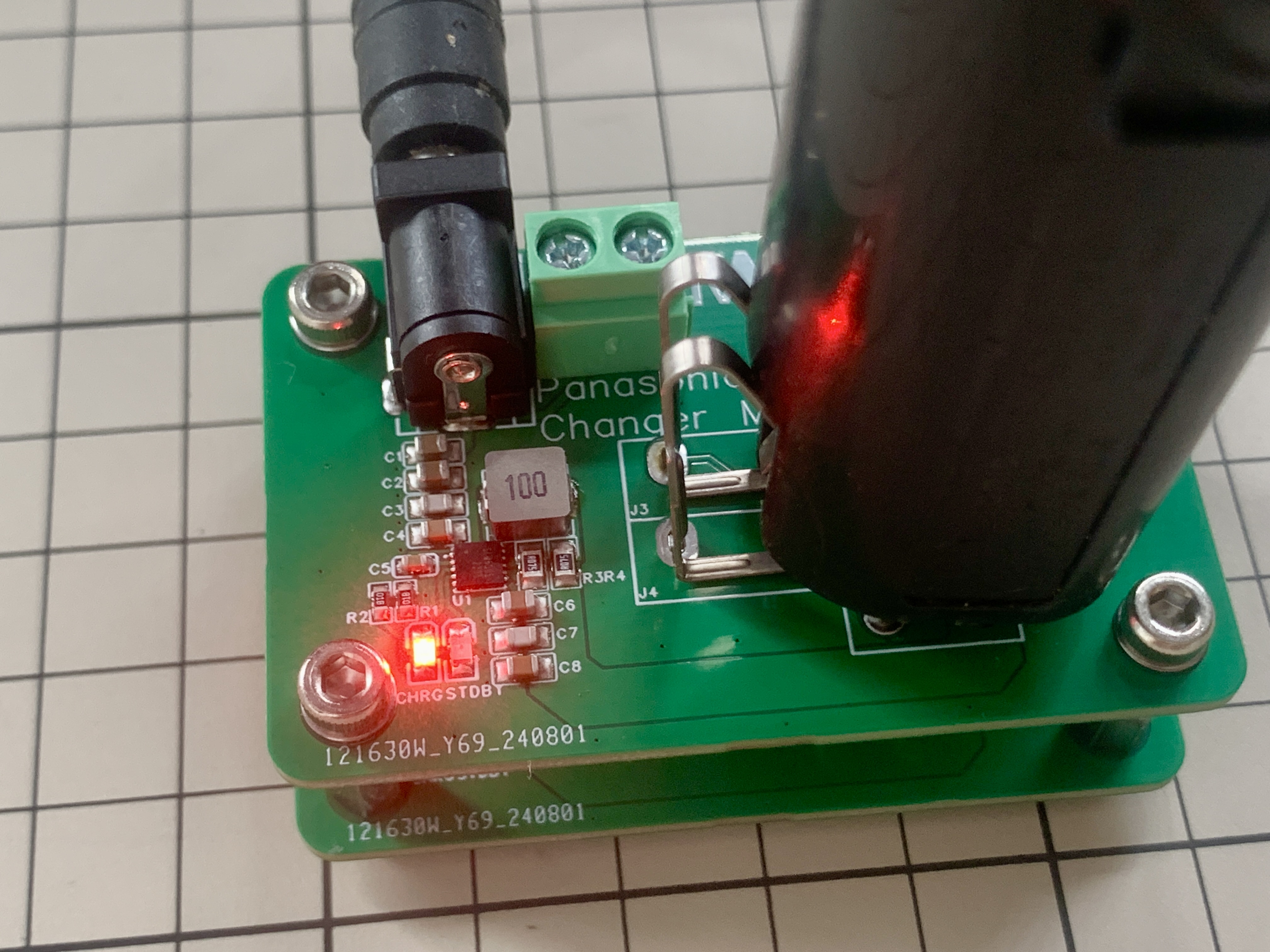
at
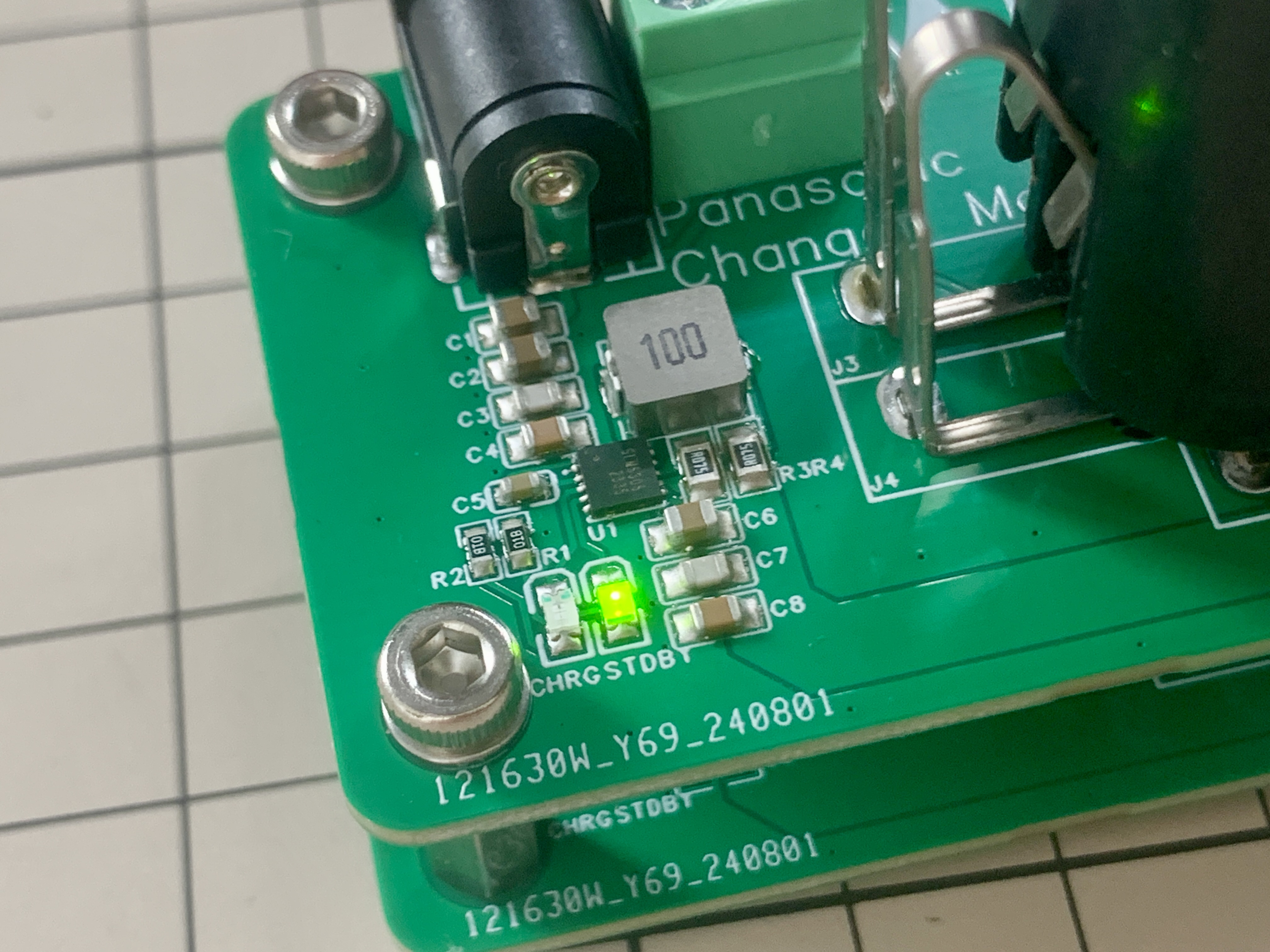
an input voltage of 5V, noticeable heat generation at 12V, and significant heat generation at 24V.
PDF_SLM6305 4.2V2A Wide Input Charger.zip
Altium_SLM6305 4.2V2A Wide Input Charger.zip
PADS_SLM6305 4.2V2A Wide Voltage Input Charger.zip
BOM_SLM6305 4.2V2A Wide Voltage Input Charger.xlsx
93264
electronic


 京公网安备 11010802033920号

 1210A0160333FFR


