Video Link:
Bilibili Video -- Function Demonstration and Introduction
Project Overview
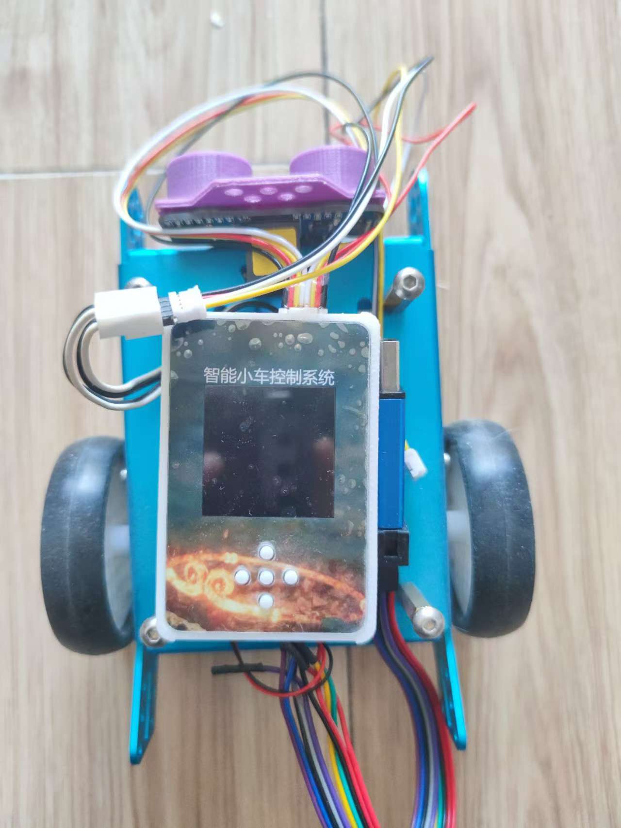
This project is an expansion board for a smart car based on the LCSC Skystar GD32F407VET6 development board - Youth Edition.
It uses two TB6612 chips
and PCA9685-16-channel servo motors for driving, with 6 channels actually brought out.
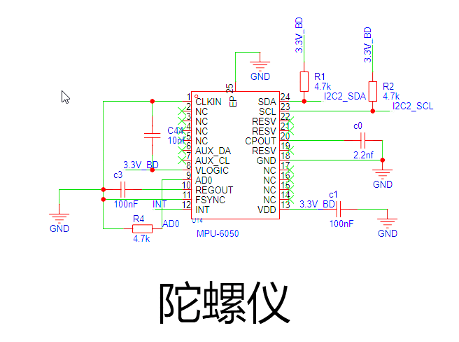
The gyroscope uses an MPU6050 .
The screen is a 1.54-inch 240x240 high-definition IPS LCD display with integrated backlight.
Project Functions
Drive 4 motors.
Drive 6 servos.
The MPU6050 gyroscope
can be connected to a 3.7V lithium battery, providing charging functionality.
1.54-inch 240x240 screen displays
Project Parameters
This design uses the MPU6050, integrating a 6-axis Motion Tracking device. It integrates a 3-axis MEMS gyroscope, a 3-axis MEMS accelerometer, and a scalable Digital Motion Processor (DMP).
This design uses the TB6612 motor driver, a Toshiba Semiconductor IC for driving motors. One TB6612FNG can drive two motors, each with two logic input pins, one output pin, and one PWM pin. The motor's operating state can be controlled by applying different levels to the two logic input pins, and the motor speed can be adjusted via the PWM input pin.
The PCA9685 is selected; it is a 16-channel PWM servo motor driver based on the I2C bus. Internally, it integrates 16 PCA6124 PCA bus servo drivers, providing independent PWM control signals for 16 servo motors. Each channel can independently set the PWM width, thereby precisely controlling the servo motor's rotation angle.
The
project consists of the following parts: charging section, motor drive section, servo drive section, and gyroscope section.
The charging circuit uses an IP5306 and includes a switch.

The TB6612 consists of two
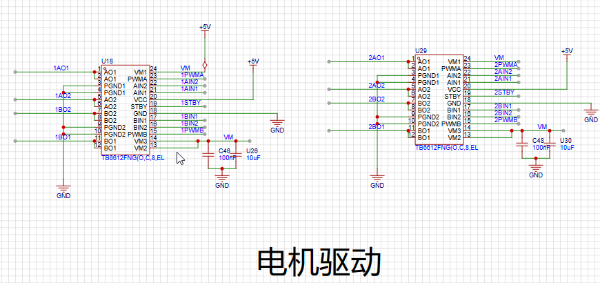
servo motor drivers as shown below. The actual value uses a 6-channel PWM output

gyroscope circuit. AD0 grounding
software code
is available in the attached zip package.
Notes:
No
assembly process
provided. Actual
product image omitted.


Smart Car Expansion Board.zip
202410042131~1.mp4
Car video.mp4
PDF_SkyStar GD32 Smart Car Expansion Board.zip
Altium_SkyStar GD32 Smart Car Expansion Board.zip
PADS_SkyStar GD32 Smart Car Expansion Board.zip
BOM_SkyStar GD32 Smart Car Expansion Board.xlsx
91572
LCSC Skystar Semiconductor Refrigerator
LCSC SkyStar Semiconductor Refrigerator Extended Version
Project Introduction:
A LCSC SkyStar semiconductor refrigerator expansion board, supporting 40-pin development boards such as STM32F103 core board and GD32E230 core board.
Project Function:
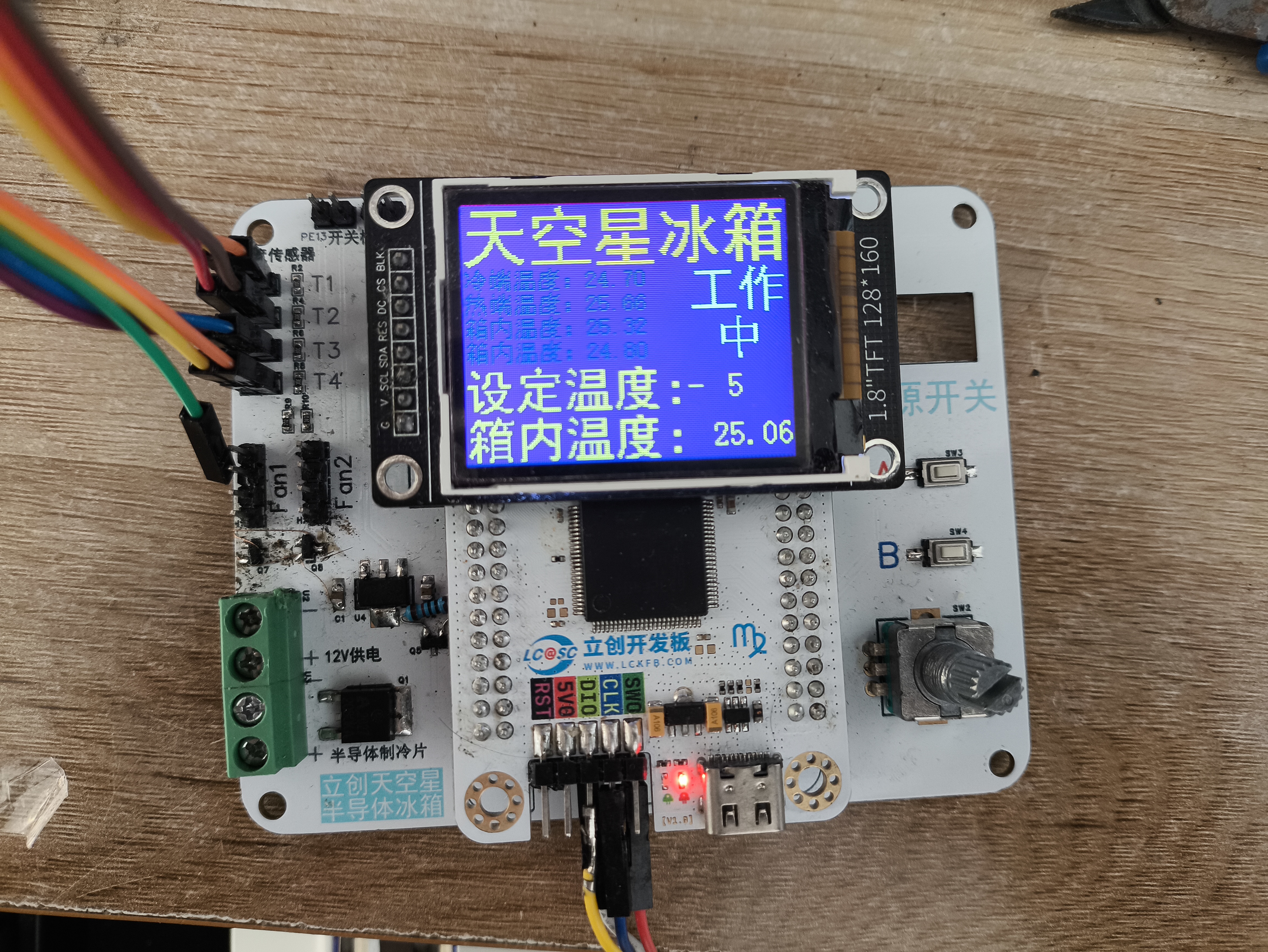
A semiconductor refrigerator control board based on GD32F407VET6.
Project Parameters:
GD32F407VET6
12705 semiconductor cooling chip ,
CPU cooling fan
, 10k thermistor (measuring cold junction, hot junction, and internal temperature),
3V lighting.
Precautions:
Ensure the TFT screen interface definition is consistent.
The display interface uses an 8-pin extended female connector.
Assembly Process:
Uses M3x8+6 hex studs, M3x5 machine screws, and M3 nuts.
Actual Product Image.

Program code.rar
main.c
PDF_LCSC SkyStar Semiconductor Refrigerator.zip
Altium_LCSC SkyStar Semiconductor Refrigerator.zip
PADS_LCSC Sky Star Semiconductor Refrigerator.zip
BOM_LCSC Skystar Semiconductor Refrigerator.xlsx
91574
CH32V307-based quadcopter drone flight control system
The CH32V307 is used as the main controller, the IMU is an Mpu6050, the magnetometer is a QMC7983, and a barometer is a BMP280. It features one-click download and debugging via USB-C and only supports the CRSF protocol.
Hardware Notes:
H3 is the ELRS receiver serial port. Receiver reference: https://oshwhub.com/vinvaa/elrs2-4g. It has a 5V power output. Other interfaces are for the expansion of
the onboard magnetometer QMC7983. However, due to a design error, it was not cascaded to the MPU6050 but instead connected to the same I2C bus as the MPU. Additional programming is required to resolve this, so it is not used, but it can be used for expansion. After modification, it can be used for filtering and inertial navigation. The onboard
TF card was not tested.
The onboard barometer BMP280 was tested, but its accuracy is poor.
The remote controller and receiver use a radio protocol; I used the ELRS radio protocol. The receiver and flight controller can only use the CRSF serial protocol. When designing or purchasing a receiver, please note
the following: Frame: MARK4, 7-inch, Motors: 1300kV, Three-bladed propeller,
Flight controller USB- Type-C supports one-click download. This Type-C port integrates serial port, download, and debugging.
H1 is an optical flow meter interface, supporting the Microspace MTF-01 and MTF-02 optical flow meters (note the wiring sequence). However, due to the lack of a magnetometer for data fusion, the integration effect is poor, and the coordinate calculation is inaccurate. Furthermore, the program only reads data and calculates coordinates; there is no program for controlling the fixed point.
After power-on, the firmware needs to be programmed into the CH549G chip using WCHISPTool_Studio before Type-C can be used for debugging the flight controller and serial printing. The firmware is located in the attached WCHLINK_V2.10.bin. Software Notes:
Use Mount River. The IDE manages the project and compilation
, while FreeRTOS manages the processes. To modify this, please go to User/RTOS_apps/.
Example code can be found at https://github.com/YifeiNie/CH32_FPV.git.
The aircraft is fully flyable. If problems occur during replication, it's definitely due to incorrect parameter settings or wiring issues. If the problem persists or a bug is confirmed, please contact @nieyf.
My hardware and software design capabilities are limited, and flight performance cannot be guaranteed. The PID parameters need further tuning.
Simply connect to the computer via USB and power on. You can view the flight control information through a serial port assistant. If it's garbled, please check if the baud rate is set to 230200.
The Print_status_task() function in the User/RTOS_apps/Print_status.c file is used to print various information. You can see different types of information by uncommenting and modifying the source code.
***Due to unknown reasons, possibly a software bug or a chip design issue, the PWM output occasionally experiences small, very short-duration jumps. For custom-made brushless ESCs using open-source ESC firmware (such as AM32), there is a chance this will be identified as a fault and the ESC will restart, causing one of the motors to suddenly stop during flight, resulting in serious consequences (crash/burnt MOSFETs or driver). The solution is to modify the ESC firmware to increase the number of fault detections. If more than three faults occur within a certain period, it is considered a genuine fault, and the problem will be solved. (Based on testing, various commercial ESCs can be used without faults.) Other precautions:
The example code is for reference only. Safety must be taken seriously when debugging drones! The project members are not responsible for any safety issues or property damage.
This project applies to various commercial brushless ESCs, but you must pay attention to the wiring sequence! Wiring sequence! Wiring sequence!
Due to my limited design capabilities, many wiring sequences are not direct-plug and are not foolproof. You must pay close attention, especially to how the output signals of the four motors of the quadcopter are connected and correspond. You must confirm clearly!
You must confirm the positive and negative terminals of the ESC power supply on the distributor board, as two of them are reversed!
You must confirm the function of each channel on the remote controller before test flight and make appropriate modifications.
Video 1.mp4
Image 1.png
WCHLINK_V2.10.bin
PDF_CH32V307-based Quadcopter Drone Flight Controller (with Flight Controller Firmware).zip
Altium_CH32V307-based Quadcopter Drone Flight Controller (with Flight Controller Firmware).zip
PADS_CH32V307-based Quadcopter Drone Flight Controller (with Flight Controller Firmware).zip
BOM_CH32V307-based Quadcopter Drone Flight Controller (with Flight Controller Firmware).xlsx
91575
electronic


 京公网安备 11010802033920号

 HCC4022B


