1. Project Background
This project is a CW32 voltmeter and ammeter training camp jointly conducted by JLCPCB and Sinyuan Semiconductor. This is my first time participating in such a project organized by LCPCB EDA. I essentially completed the entire product development process by following along. Next, I will introduce and test the board I built. The digital voltmeter and ammeter project covers multiple aspects, including microcontroller circuit design and implementation, signal acquisition and processing circuit design, user interface development and optimization, and product appearance design. It integrates knowledge from multiple fields such as electronic technology, microcontroller programming, circuit design, and industrial design. This project has the following highlights:
It adopts a core board plus expansion board design concept and uses plug-in device design, making learning simpler and exploration more in-depth;
the core board uses the domestic Wuhan Sinyuan Semiconductor CW32 as the main controller, while also being compatible with other similar development boards; however, the CW32 has advantages.
The project has a high degree of integration and strong practicality; after completion, it can be used as a desktop everyday instrument;
the project has abundant learning materials, including circuit design tutorials, PCB design, code programming learning, and training for engineers' debugging skills.
2. Project Attributes:
This project is based on an official case study and improved upon from a training camp jointly organized by JLCPCB and Wuhan Xinyuan Semiconductor. This version is being publicly released for the first time.
3. Introduction to the Open Source License :
GPL 3.0
is the GNU General Public License. If a product under the GPL license is used in a project, then that project must also use the GPL license, meaning it must be open source and free.
The GPL's premise is the open-source and free use of code, and the open-source and free use of referenced, modified, and derived code, but it does not allow the release and sale of modified and derived code as closed-source commercial software.
The most significant characteristics of the GPL are "viral distribution" and "disallowing closed-source commercial distribution." Linux, which we are familiar with, uses the GPL license.
The basic spirit of GPL 3.0
allows free use, copying, modification, and distribution of protected programs, but the source code must be provided during distribution.
Fees can be charged. For example, fees can be charged for the distribution of object code and source code, and for software maintenance (mainly providing technical support, hereinafter referred to as "maintenance"); however, license fees, royalties, patent license fees, and authorization fees cannot be charged.
All contributors to GPL programs automatically and freely provide patent licenses, promising not to sue for patent infringement (provided you comply with the GPL).
GPL programs allow others to crack them. If used on consumer hardware, modification and installation programs must be permitted.
4. Hardware Part
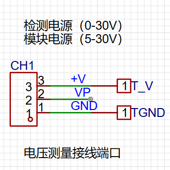
1. Voltage Sampling Circuit
This project uses a voltage divider circuit to achieve high voltage acquisition, designed to acquire voltages up to 100V, currently configured to acquire voltages of 0-30V. The voltage divider resistors in this project are designed to be 220K+10K, therefore the voltage division ratio is 22:1 (ADC_IN11).

This project also includes circuits used to simulate voltage measurement, measurement calibration, and measurement calibration aids.
2. The current sampling circuit
in this project uses a low-side current sampling circuit for current detection. The low-side of the sampling circuit
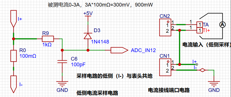
is designed to share a common ground with the development board's meter interface.
The sampling current in this project is 3A, and the selected sampling resistor (R0) is 100mΩ. The selection of the sampling resistor mainly needs to consider the following aspects:
the maximum value of the pre-designed measurement current; in this project,
the voltage difference caused by the 3A current sensing resistor; generally, it is not recommended to exceed 0.5V;
the power consumption of the current sensing resistor should be selected based on this parameter. Considering the power consumption (temperature) issue under high current, a 1W packaged metal wire-wound resistor was selected.
The voltage amplification factor across the current sensing resistor: no operational amplifier is used in this project to build the amplification circuit, therefore the factor is 1.
Then... Based on the above parameters, the current sensing resistor value is selected
as follows: Since this project does not use an amplifier circuit, a larger sampling resistor is needed to obtain a higher measured voltage for measurement.
Considering that a larger resistor will result in a larger voltage drop and higher power consumption, an unlimited selection of a larger resistor is not possible.
This project uses a 1W package resistor, corresponding to a power rise of 1W.
Based on the above data, a 100mΩ current sensing resistor is selected. According to the formula, 3A * 100mΩ = 300mV, 900mW.
To cope with different operating environments, especially high-current scenarios, the R0 resistor can be replaced with constantan wire or a shunt. The choice of alternative can be made based on the actual application scenario. For safety and educational purposes, this project will not discuss measurements exceeding 3A, but the principle remains the same. 3.
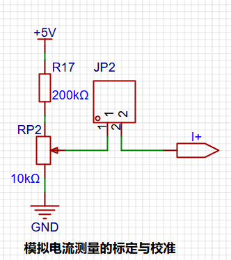
Auxiliary circuits for simulating current measurement, calibration, and verification.
The digital tube display circuit

uses two 0.28-inch three-digit common-cathode digital tubes as display devices in this project. Compared to displays, digital tubes have better visibility in complex environments. The brightness of the digital tubes can be increased by using smaller current-limiting resistors to meet the needs of the actual usage environment. Furthermore, digital tubes have better mechanical properties and are not as easily damaged by external forces as displays. They are widely used in industrial applications requiring stability and reliability. From a development board learning perspective, this makes it easier to learn electronic measurement principles and related development in a targeted manner.
In this project, after actual testing, the current-limiting resistors (R1~R6) of the digital tubes were configured to 300Ω. The corresponding brightness, whether for red or blue digital tubes, had good visibility and was soft and not glaring.
3. TL431 Circuit Design for Voltage Measurement Calibration:

This project adds an extra TL431 circuit to provide a 2.5V reference voltage. This can be used to provide an external voltage reference for the chip to calibrate the AD converter. From a product design perspective, due to the inherent ADC performance advantages of the CW32, this circuit is not necessary.
5. Software:
The software was designed by JLCPCB and Wuhan Xinyuan Semiconductor. Detailed official documentation is available, so I won't elaborate further here. I will only describe some key points, such as the function and usage of the three buttons on the board.
Calibration Operation Method:
This example uses button operation for calibration. The specific operation method is as follows:
Define 5 working modes. The K1 key is used to switch display modes. The K2 key sets the parameter value for the corresponding mode and saves it to FLASH. The K3 key returns to mode 0.
Mode 0: Displays normal voltage and current values (the upper row of digital tubes displays the voltage value *.V or .*V automatically switching, the lower row displays the current value _.**A).
Mode 1: 5V voltage calibration value setting. The top row of the digital display shows 5.05. The bottom row displays the current voltage value in .V or ._V. In this mode, the multimeter should be set to 5.00V to measure the voltage level. After pressing the K2 key, the current value will be calibrated as 5V.
Mode 2: 15V Voltage Calibration Setting. The top row of the digital display shows 5.15. The bottom row shows the current voltage value in _V or ._V. In this mode, the multimeter should be set to 15.0V when measuring the measured bit. Pressing the K2 key will calibrate the current value to 15V.
Mode 3: 0.5A Current Calibration Setting. The top row of the digital display shows A.0.5. The bottom row shows the current current value in _.**A. Pressing the K2 key will calibrate the current value to 0.5A.
Mode 4: 1.5A Current Calibration Setting. The top row of the digital display shows A.1.5. The bottom row shows the current current value in *.**A. Pressing the K2 key will calibrate the current value to 1.5A.
For detailed software tutorial documents, please click >>> Software-related Design
6. BOM List Notes
1. This circuit design uses the LCSC Diwenxing development board as the main controller, employing a modular design for learning purposes. You can purchase it from the LCSC development board website.
2. This circuit design uses a 0.28-inch common cathode digital tube; you can choose the color yourself.
3. This circuit uses an 8550LDO with a maximum input voltage of 40V, which is very convenient with VP power supply. 4.
This circuit design uses a 2mm banana-head female connector for easy insertion of multimeter probes for measurement; please do not purchase the wrong specification!
5. Note! Please double-check the BOM list when placing your order to ensure nothing is missing. Out-of-stock items may be removed from the store, and purchasing materials will extend your learning time.
7. Demonstrate the project and record a video for uploading. For a
detailed video explanation, please click >>> This is a video


 京公网安备 11010802033920号

 2200RG3G00423GA


