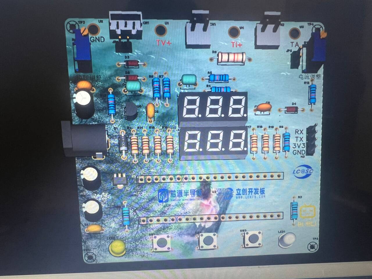
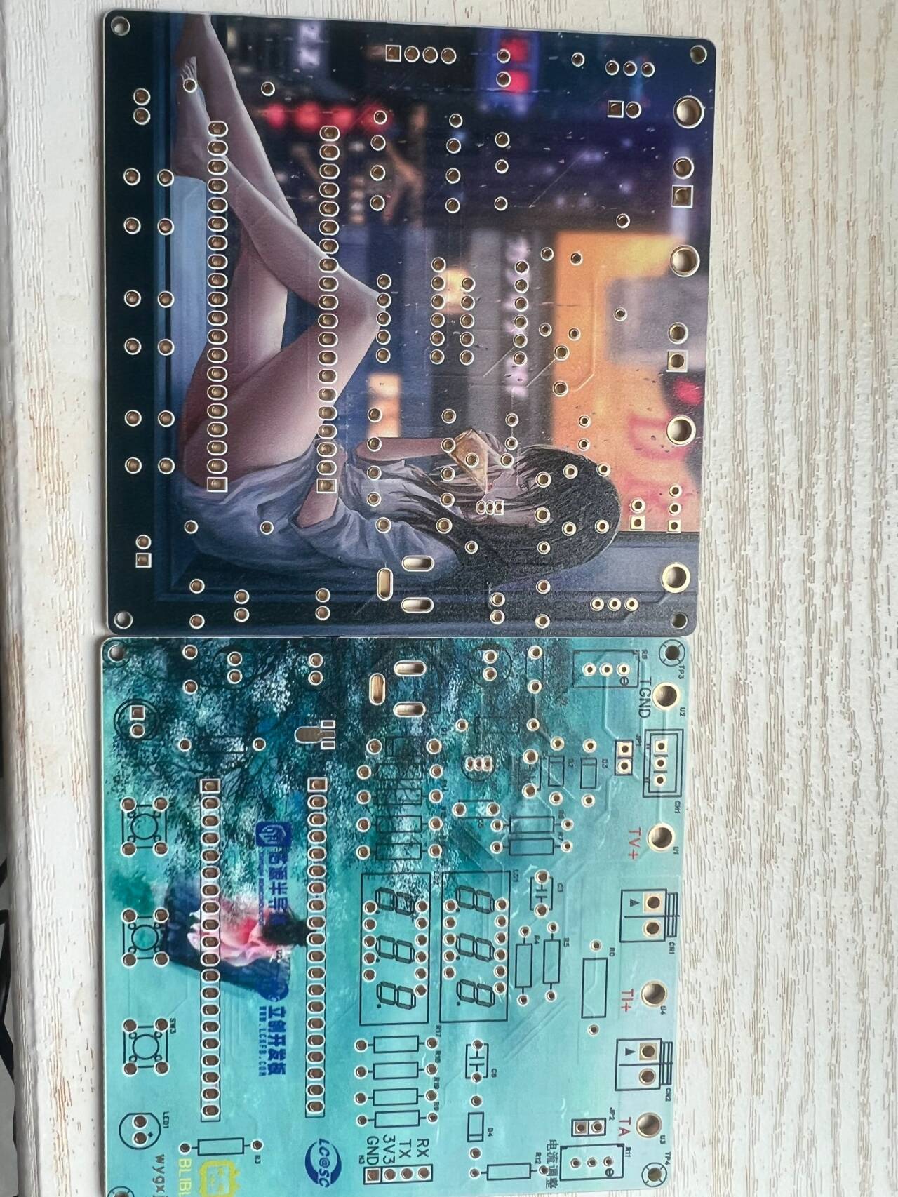
This is a voltage and current measuring meter based on the LCSC CW32 development board. The circuit uses LCSC's color PCB immersion gold process, making the circuit more reliable and aesthetically pleasing. [Images !
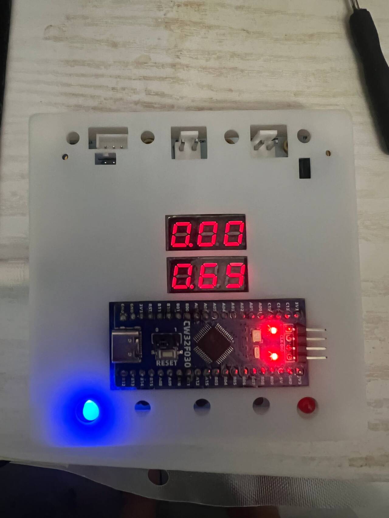
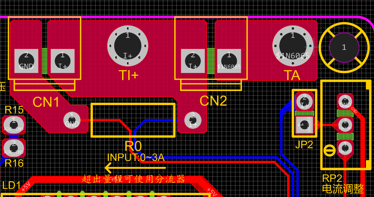
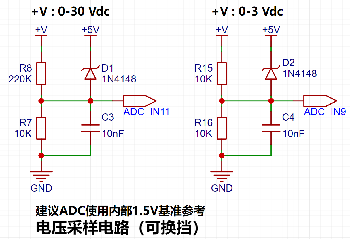
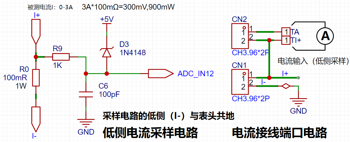
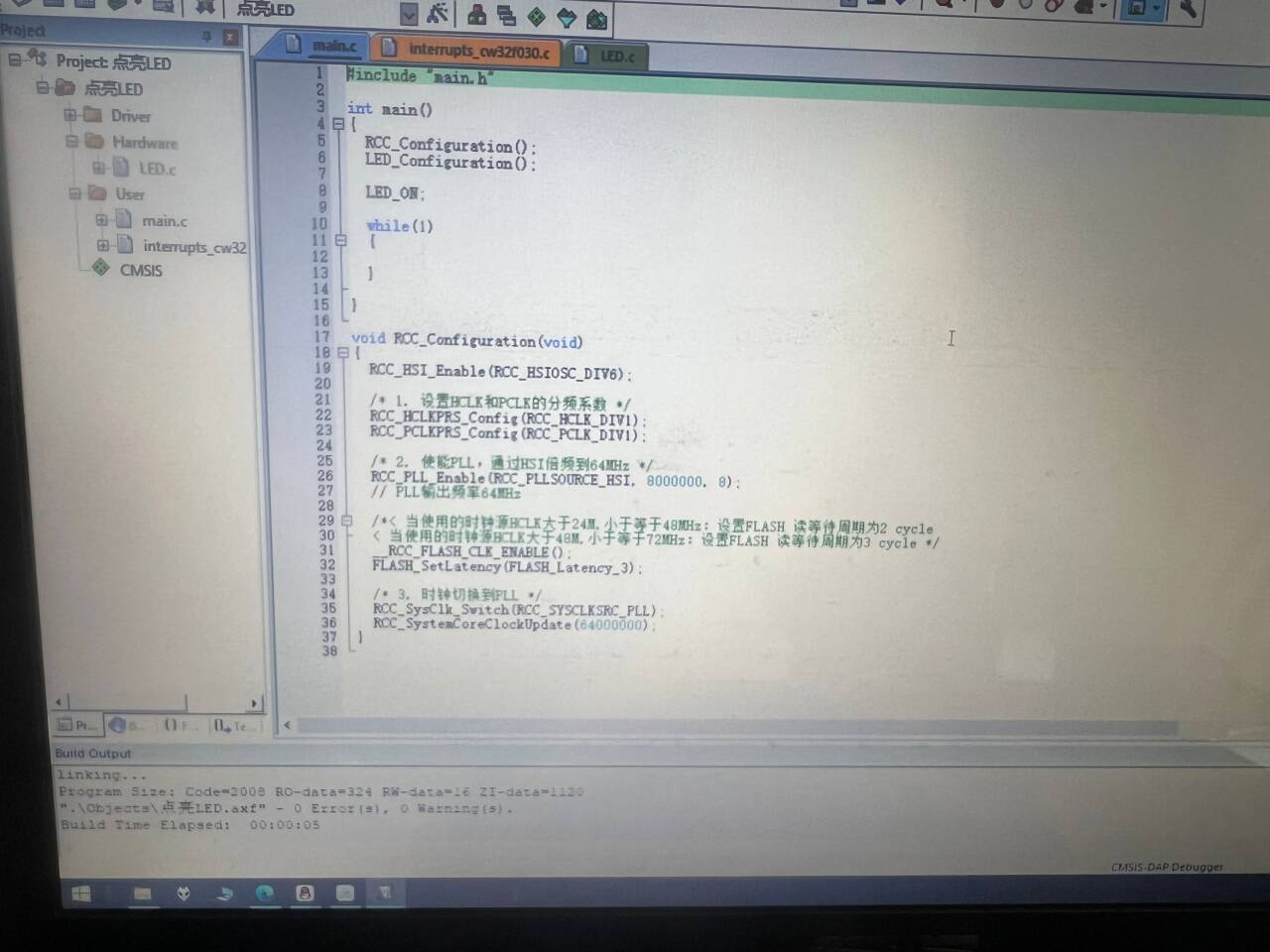
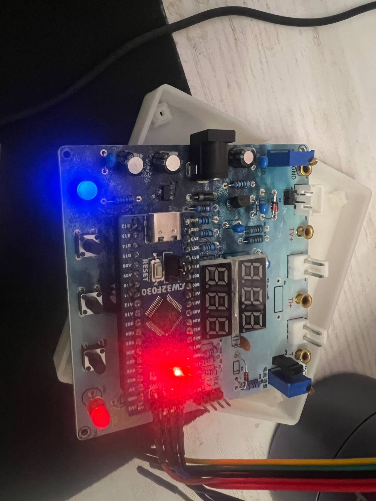
[e1b86cc7e397551504a3610f37036a1c_720.png] [ 62374a529e42e833e6d15ddf923f1af2_720.png] The casing and panel are also 3D printed , making the product complete! ![a79227aacce984c1d922adbf53381fe8_720.png] ![676828e3eac44ae58389dd87c5548b69_720.png] The power supply section adopts a wide voltage input of 5V to 12V, and uses the SE85550k2 low dropout LOD chip to ensure stable operation of the power supply. At the same time, a reverse connection protection diode is connected in series in the circuit to ensure the safety of the power input . ![image.png] The core board uses the LCSC CW32F030C8T6 development board (core board). Its advantages are as follows: Wide operating temperature: -40~105℃ ![image.png] Wide operating voltage: 1.65V~5.5V (STM32 only supports 3.3V system) Strong anti-interference: HBM ESD 8KV All ESD reliability reaches the highest level of international standards (STM32) (ESD2KV) This project focuses on a better ADC: a 12-bit high-speed ADC achieving ±1.0LSB INL 11.3ENOB, multiple Vref reference voltages... ... (STM32 only supports VDD=Vref). Stable and reliable eFLASH technology. (Flash0, etc.) This project uses a voltage divider circuit to achieve high voltage acquisition, designed to acquire voltages up to 100V, currently configured to acquire voltages of 0-30V. The ADC reference voltage in this project is 1.5V, which can be configured through the program. During the design of this project, an additional 1N4148 (D1, etc.) was added to the sampling circuit as a clamping diode to minimize the risk of chip pin damage due to incorrect voltage input during learning and debugging. Diode clamping is an important electronic circuit design technique. Its main function is to protect the circuit by limiting the voltage amplitude, preventing damage or malfunction caused by excessively large or small signals. This project uses a low-side current sampling circuit for current detection. The low-side of the sampling circuit shares a common ground with the development board's meter interface. The sampling current is 3A, and the selected sampling resistor (R0) is 100mΩ. The selection of the sampling resistor mainly needs to consider the following aspects: the maximum value of the pre-designed measurement current; the voltage difference caused by the 3A current sensing resistor in this project; generally, it is not recommended to exceed 0.5V ; the power consumption of the current sensing resistor should be selected based on this parameter; considering the power consumption (temperature) issue under high current, a 1W packaged metal wire-wound resistor was selected in this project; the voltage amplification factor across the current sensing resistor: Since no operational amplifiers were used to build the amplification circuit, the PCB layout for a gain of 1 requires special attention. Although the I- network and GND network are electrically the same, it's important to note that a large current flows through I-, making it a "power ground." Even though this point is grounded, current fluctuations can cause changes in the network level, thus treating it as an "interference source." The GND network is the negative terminal of the meter's power supply, i.e., "signal ground." Furthermore, since the microcontroller's AGND and the meter's GND are not isolated, the meter's GND can be considered a "sensitive ground," requiring protection from interference. In circuit design, avoid connecting all GNDs together indiscriminately. This is also why copper plating was not used in this project design. In the diagram above, the yellow arrows indicate the path of high current flow: current flows in through the I+ pin of the interface, through the sampling resistor, and out through the I- pin of the interface. Some may wonder why two current sampling interfaces, CN1 and CN2, are provided. Current sampling is connected in series to the circuit under test. Two interfaces are provided for debugging (i.e., for learning development board requirements). For normal measurements, only CN1 needs to be connected. When the project requires connecting to devices such as a multimeter for comparison and verification, pin 1 of CN2 (red wire - current in) and pin 2 of CN1 (black wire - current OUT) must be used simultaneously. This project uses a voltage divider circuit to achieve high voltage acquisition, designed to acquire up to 100V; the current configuration acquires voltages from 0-30V. [Image 1] The sampling current designed for this project is 3A, and the selected sampling resistor (R0) is 100mΩ. The following aspects should be considered when selecting the sampling resistor: the maximum value of the pre-designed measurement current; the voltage difference caused by the 3A current sensing resistor in this project; generally, it is not recommended to exceed 0.5V ; the power consumption of the current sensing resistor should be selected based on this parameter; considering the power consumption (temperature) issue under high current, a 1W packaged metal wire-wound resistor was selected; the voltage amplification factor across the current sensing resistor: no operational amplifier is used to build the amplification circuit in this project, therefore the factor is 1. [Image 2] Development environment installation (MDK 5.33 version recommended), DAPLINK downloader, firmware library. The firmware library can be downloaded from the official website: www.whxy.com. Common debuggers such as STLINK, DAPLINK, PWLINK, WCHLINK, JLINK, etc., that support Cortex-M are acceptable. I used PWLINK, where verf is 3.3V. ![e59aa5fdd74ee7ca86d303e0f5bc3e92_720.png] Connect the development board, open Example 1, compile without errors, flash and light up LED1 . ![1c02a3354d6f456dd16023a89adb5990_720.png] ![eef096da0e4ded95ef6a60a671dedd00_720.png] Directly input Experiment 9. [e37f04b60d57849cbbf34265f5f64b93_720.png] Shorting caps on JP1 and JP2 respectively simulates the measurement of internal voltage and current. A multimeter is connected, and the data is basically consistent. Use button 1 to select the function and button 2 for calibration, as follows: Define 5 working modes. Key K1 is used to switch display modes. Key K2 sets the parameter value for the corresponding mode and saves it to FLASH. Key K3 returns to mode 0. Mode 0: Displays normal voltage and current values (the upper row of digital tubes displays the voltage value *.V or .*V automatically switches, the lower row displays the current value _.**A).


Mode 1: 5V Voltage Calibration Setting. The top row of the digital display shows 5.05. The bottom row displays the current voltage value in _V or ._V. In this mode, the multimeter should be set to 5.00V when measuring the measured bit. Pressing the K2 key will calibrate the current value to 5V.
Mode 2: 15V Voltage Calibration Setting. The top row of the digital display shows 5.15. The bottom row displays the current voltage value in _V or ._V. In this mode, the multimeter should be set to 15.0V when measuring the measured bit. Pressing the K2 key will calibrate the current value to 15V.
Mode 3: 0.5A Current Calibration Setting. The top row of the digital display shows A.0.5. The bottom row displays the current current value in _.**A. Pressing the K2 key will calibrate the current value to 0.5A.
Mode 4: 1.5A Current Calibration Setting. The top row of digital tubes displays A.1.5. The bottom row displays the current value *.**A. Pressing the K2 key calibrates the current value as 1.5A. Attached video demonstration:
In actual use, the voltage at I+ simulates the voltage drop across the unsoldered 100mΩ sampling resistor. At this time, the simulated measured current value I
measured = the voltage value Vi+ ÷ 100mΩ, which is also exactly equal to the measured voltage value multiplied by 10. That is, it provides a simulated current measurement range of 0~2.38A. Set the multimeter or high-precision benchtop digital multimeter to the voltage measurement port, with a range within 3V. Insert the black negative probe into the T_GND interface next to the voltage measurement terminal, and the red positive probe into the TI+ port for current measurement to measure the actual voltage value of I+.


 京公网安备 11010802033920号

 HF9110-009M02


