Problem Requirements
: Design a Waveform Generator Based on a Microcontroller
Content:
1. Design a waveform generator capable of generating more than 3 waveforms;
2. Design waveform selection buttons (using 3 independent buttons);
3. Display waveform patterns using a dot matrix;
4. Output two waveforms simultaneously;
5. Display frequency.
Problem Analysis:
This design, after analysis and comparison, adopts a traditional method to implement a multi-functional waveform generator. Leveraging the advantages of high-performance microcontrollers—high processing speed and strong system integration—this designed signal generator is simpler in hardware, easier to understand and implement, and has a clearer design concept, making it easier to control frequency and amplitude. Depending on the application and the types of waveforms required, the specific performance requirements of the waveform generator will vary.
Different design schemes should be selected based on different design requirements. Typically, waveform generators need to generate sine waves, square waves, triangle waves, and sawtooth waves. In some cases, arbitrary waveform generation may also be required. Common performance indicators for various waveforms include: waveform frequency, amplitude requirements, frequency stability, and accuracy.
The overall design scheme block

diagram and schematic diagram are described
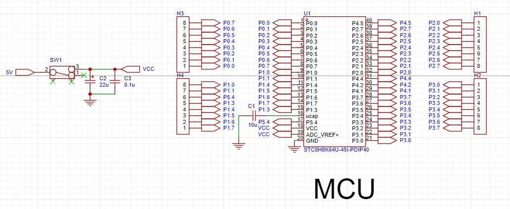
below. The STC8H8K64U is used as the main control chip. The STC8H8K64U is a powerful microcontroller, ideal for various embedded applications due to its ultra-high-speed 8051 core, abundant on-chip resources, and flexible expansion capabilities. This microcontroller uses a 1T 8051 core, which is more than 12 times faster than the traditional 8051, providing faster processing speed and higher efficiency, while remaining compatible with traditional 8051 instruction code for easy development and migration. The STC8H8K64U provides up to 64KB of Flash memory, supporting single-page erase and multiple erase/write operations for convenient storage of user code. Furthermore, it boasts abundant on-chip resources, including 22 interrupt sources, 4 interrupt priority levels, an internal high-precision clock, 5 timers, 4 high-speed serial ports, 8 advanced PWM channels, SPI, I2C, MDU16, USB, RTC, I/O port interrupts, DMA, LCM drivers, etc., meeting the needs of complex applications. The STC8H8K64U also supports in-system emulation, in-system programming, and user-configurable EEPROM size, facilitating development and application. It has a wide operating voltage range (1.9V~5.5V) and a wide operating temperature range (-40℃~85℃), making it suitable for various environments and demonstrating broad application prospects in various embedded fields, such as industrial control, consumer electronics, communication equipment, medical equipment, and automotive electronics.
Therefore, this project selects the STC8H8K64U as the controller, and its basic functions can meet the timing and counting requirements of this system.
The STC8 series with hardware USB supports direct USB emulation/ISP programming. The official website (https://www.stcaimcu.com/forum.php?mod=viewthread&tid=1554&extra=page%3D1) provides specific simulation and ISP download methods.

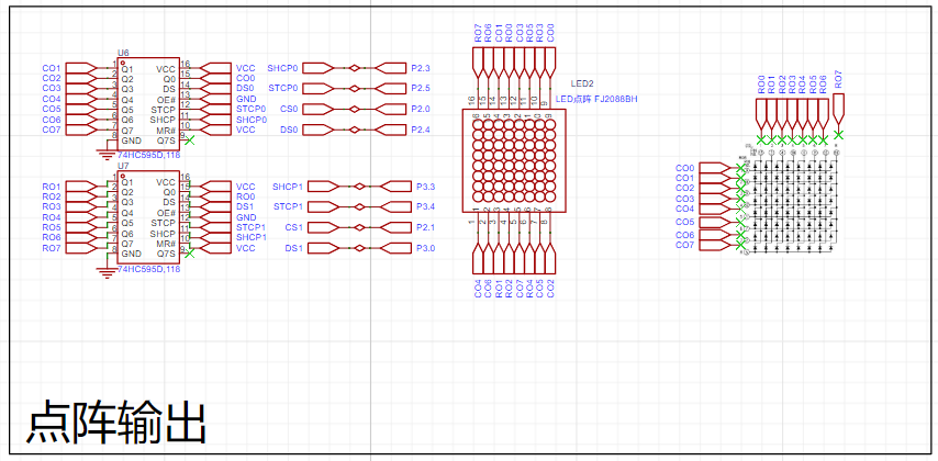
The 74HC595 is an 8-bit serial input, parallel output shift register. The parallel output is tri-state. On the rising edge of SCK, serial data is input from SDL into the internal 8-bit shift register and output by Q7'. Parallel output occurs when the data in the 8-bit shift register is stored in the 8-bit parallel output register on the rising edge of LCK. When the control signal at the serial data input terminal OE is low, the output value at the parallel output terminal equals the value stored in the parallel output register. An
8×8 dot matrix screen is used for the waveform dot matrix display, which is too many pins for a 51 microcontroller with only 16 pins; therefore, the 74HC595 chip is used to expand the I/O pins. The STC89C52 serially inputs data to the 74HC595, which then outputs it in parallel. This design allows control of a device with more pins using fewer pins.
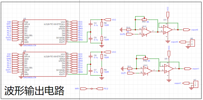
The DAC0832 mainly consists of four parts: an 8-bit input register, an 8-bit DAC register, an 8-bit D/A converter, and an input control circuit. An 8-bit input register stores the digital value sent from the host, buffering and latching the input digital value, and is controlled by [a specific control/mechanism]. An 8-bit DAC register stores the digital value to be converted, and is controlled by [another specific control/mechanism]. The 8-bit D/A converter outputs an analog current proportional to the digital value. An input control circuit composed of AND and NOT AND gates controls the gating or latching state of the two registers. The DAC0832 is connected to an inverting amplifier to realize the current-to-voltage conversion, so the polarity of the output analog signal is opposite to the polarity of the reference voltage.
Software Description:
The pseudocode of the overall program:

When the microcontroller starts working, Timer 0 is triggered and starts counting, and the OLED starts displaying the waveform frequency. When Timer 0 triggers an interrupt, it outputs the waveform code to the DAC0832, which outputs the final waveform through the inverting amplifier circuit. Simultaneously, it continuously checks for button presses; if a button is pressed, the corresponding function is executed. When the waveform is adjusted, the OLED synchronously outputs the current waveform shape and frequency, and the currently selected waveform shape can be seen from the content displayed on the OLED.
Code block:
void main() //Main function
{
P0M0 = 0x00; P0M1 = 0x00; //Set P0.0~P0.7 to bidirectional port mode
P1M0 = 0x00; P1M1 = 0x00; //Set P1.0~P1.7 to bidirectional port mode
P2M0 = 0x00; P2M1 = 0x00; //Set P2.0~P2.7 to bidirectional port mode
P3M0 = 0x00; P3M1 = 0x00; //Set P3.0~P3.7 to bidirectional port mode
OLED_Init();//Initialize OLED
OLED_ColorTurn(0);//0 Normal display, 1 Inverted color display
OLED_DisplayTurn(0);//0 Normal display, 1 Screen flip display
OLED_ShowString(0,1,"CHANNAL_1: 10 Hz",16);
OLED_ShowString(0,4,"CHANNAL_2: 10 Hz",16);
m = 65536-(50000/pinlv);
a=m/256; // Load the high 8 bits
b=m%256; // Load the low 8 bits
init_interrupt();
CS0=1; // Chip select, active low
CS1=1; // Chip select, active low
WR1=1; // Data latch write strobe input, active low
while(1) {}
}
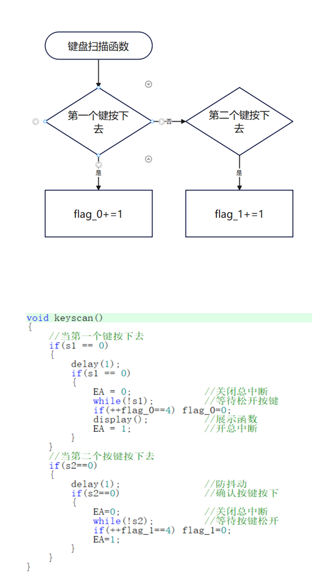
Keyboard scanning program design
The keyboard scanning function is used to read the key information in the external interrupt service routine to assign values to the waveform flag bits flag_0 and flag_1, so as to control the shape of the output waveform. When key 2 is pressed, the value of flag_0 is incremented by 1, and the corresponding controlled waveform will change. When flag_0 reaches four, it will be reset to zero. When key 2 is pressed, the value of flag_1 is incremented by 1, and the corresponding controlled waveform will change. When flag_1 reaches four, it will be reset to zero.
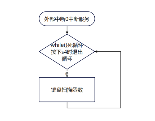
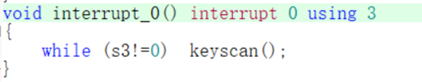
External interrupt 0 program design
External interrupt 0 is an interrupt set for waveform selection. When the INT0 pin receives a negative rising edge, it will enter the loop of executing the keyboard scanning function. To exit the loop, the S3 key must be pressed to assign values to the waveform flag bits flag_0 and flag_1, so as to control the shape of the output waveform.
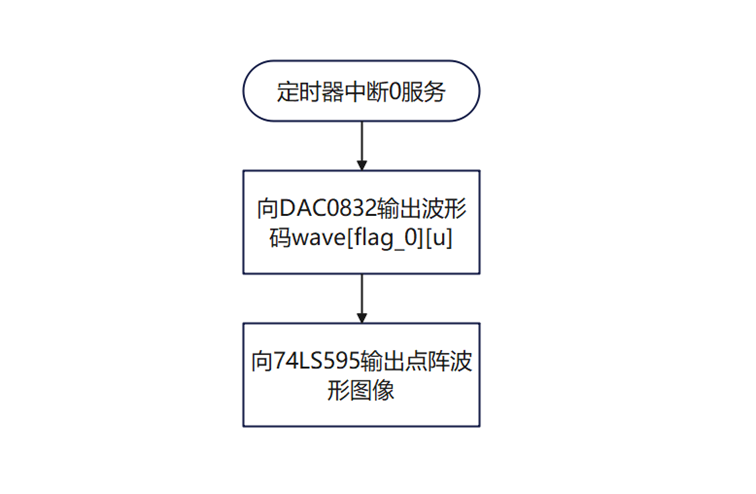
The Timer Interrupt 0 program design
uses a timer to send waveforms at regular intervals, achieving high precision. For waveform generation, instead of using functions, a code extraction method was adopted. This method is simple, clear, and logically sound, effectively fulfilling the requirement of simultaneously outputting two waveforms. It also integrates well with timer interrupts, requiring only two flag bits, and the logic is clear and easy to understand.

Physical Demonstration

Notes:
1. When designing the PCB, the package size was not considered, and the button package was drawn too small. Small buttons are difficult to press, resulting in a poor user experience.
2. The dot matrix screen orientation is incorrect; it should be rotated 90° clockwise for the display to be correct.


 京公网安备 11010802033920号

 HLMP-EH27-WU400


